![]()
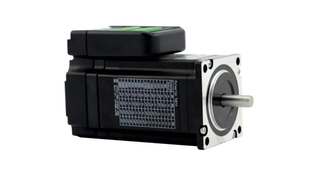
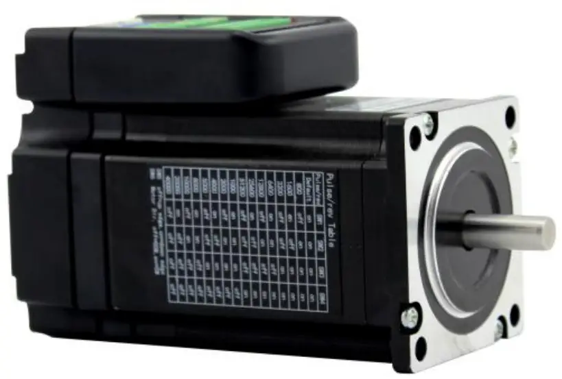
TSS57 Nema23 Integrated
closed-loop stepper motor
User Manual
Installation
1、Electrical indicators
- Voltage input range: DC: 20V~40V (usually connected to 36V)
- Maximum output current: 5A
- Pulse type: pulse + direction
- Logic input current: 7~20mA
- Echo response frequency: 0~200kHz
- Insulation resistance: 500M
2、Environmental indicators
- Storage temperature: -20 ° C ~ 80 ° C
- Operating temperature: 0 ° C ~ 55 ° C
- Use humidity: 90% RH (non-condensing)
- Vibration frequency: less than 0.5G (4.9m / s 2) 10Hz ~ 60Hz (non-continuous operation)
3、Installation dimension drawing (unit: mm)
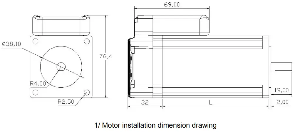
Note: Motor length L can refer to the Lichuan Catalog
Wiring
- Driver terminal description
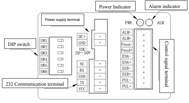
1)Power supply terminal definition
| No. | Symbol | Function definition |
| 1 | DC+ | External DC20~50V |
| 2 | GND |
2)Control signal terminal definition
| Pin | Symbol | Definition | Pin | Symbol | Definition |
| 1 | ALM- | Alarm output negative | 8 | ENA+ | Enable input positive |
| 2 | ALM+ | Alarm output is positive | 9 | DIR- | Direction input negative |
| 3 | Pend- | Positioning completed output negative | 10 | DIR+ | Direction input positive |
| 4 | Pend+ | Positioning completion output is positive | 11 | PUL- | Pulse input negative |
| 5 | ENA- | Enable input negative | 12 | PUL+ | Pulse input positive |
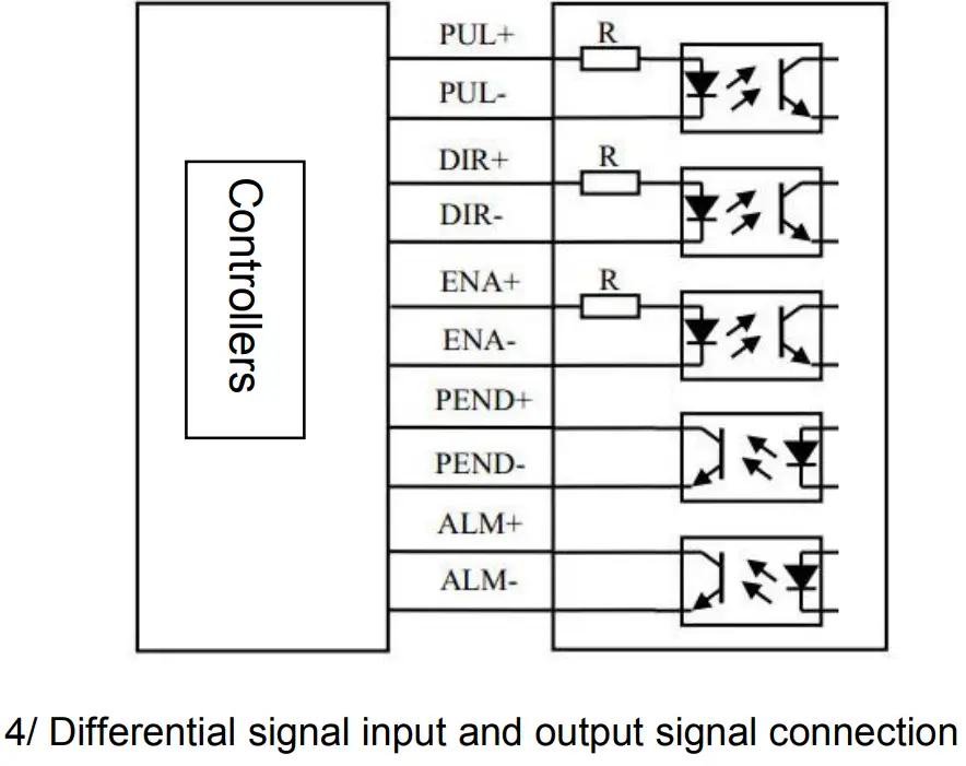
2、Control port wiring
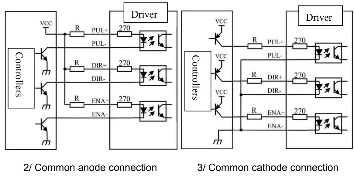
Note:
When the control signal voltage VCC = 24V,the current limiting resistor R = 3K;
When the control signal voltage VCC = 5V, the current limiting resistor R = 0;
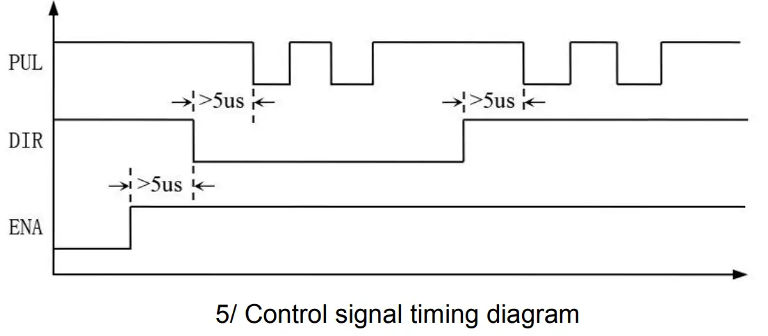
3、Control signal timing diagram
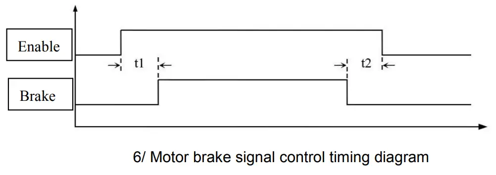
Note: T1: Brake delay start time
T2: Brake delay off time
Parameter settings
This series of drivers can be directly subdivided by the DIP switch, or the drive related parameters can be modified by the PC software.
1、DIP switch setting instructions
| Pulse/rev | SW1 | SW2 | SW3 | SW4 |
| Default | on | on | on | on |
| 800 | off | on | on | on |
| 1600 | on | off | on | on |
| 3200 | off | off | on | on |
| 6400 | on | on | off | on |
| 12800 | off | on | off | on |
| 25600 | on | off | off | on |
| 51200 | off | off | off | on |
| 1000 | on | on | on | off |
| 2000 | off | on | on | off |
| 4000 | on | off | on | off |
| 5000 | off | off | on | off |
| 8000 | on | on | off | off |
| 10000 | off | on | off | off |
| 20000 | on | off | off | off |
| 40000 | off | off | off | off |
SW5:off = Pulse rising edge trigger;on = Pulse falling edge trigger;
SW6:off = Forward;CW = Reverse;
2、Upper unite software debugging parameters description
| No. | Defination | Defaut | Range | Remark |
| 0 | Current loop proportional coefficient | 2000 | 200~8000 | |
| 1 | Current loop integral coefficient | 200 | 60~2000 | |
| 2 | Position loop low speed ratio | 3300 | 100~10000 | |
| 3 | Position loop high speed ratio | 3900 | 100~10000 | |
| 4 | Speed loop low speed ratio | 160 | 10~2000 | |
| 5 | Speed loop high speed ratio | 330 | 10~2000 | |
| 6 | Default file segmentation settings | 400 | 200~51200 | |
| 7 | Encoder pulse number per revolution | 4000 | 4000~65535 | |
| 8 | Position error alarm threshold | 4000 | 1~65535 | |
| 9 | Acceleration feed forward coefficient | 70 | 0~4096 | |
| 10 | Motor back EMF coefficient | 21 | 1~1000 | |
| 11 | Maximum weak magnetic ratio | 50 | 20~100 | |
| 12 | Speed feedforward | 70 | 0~100 | |
| 13 | Maximum output current percentage | 100 | 1~100 | |
| 14 | Speed loop integral coefficient | 100 | 0~5000 | |
| 15 | Input pulse filter selection | 1 | 0~1 | |
| 16 | Input pulse filtering time | 6400 | 50~25600 | |
| 17 | Enable active level setting | 0 | 0~1 | |
| 18 | Output port 1 resistance setting | 1 | 0~1 | |
| 19 | Output port function setting | 1 | 1~2 | |
| 20 | Self-contained selection | 1 | 0~1 | |
| 21 | Self-scaling setting | 80 | 30~100 | |
| 22 | Power-on anti-blocking option | 0 | 0~1 | |
| 23 | Open-closed control mode selection | 1 | 0~1 | |
| 24 | Current filtering frequency | 600 | 100~5000 | |
| 25 | Speed loop filter frequency | 600 | 100~5000 | |
| 26 | Speed sampling filter frequency | 100 | 10~1000 | |
| 27 | Position loop filter frequency | 100 | 10~1000 |
| No. | Defination | Defaut | Range | Remark | |
| 28 | Gravity compensation coefficient | 100 | 40~160 | ||
| 29 | Open loop current percentage | 60 | 0~100 | ||
| 30 | Debounce delay | 40 | 0~65535 | ||
| 31 | Static parameter attenuation coefficient | 150 | 1~500 | ||
| 32 | Speed integral limit percentage | 50 | 1~100 | ||
| 33 | Internal start and stop control | 0/1 | |||
| 34 | Internal running acceleration | 1~2000 | |||
| 35 | Internal running speed | 0~5000 | |||
| 36 | Internal running distance | 1~65535 | |||
| 37 | Internal running times | 1~65535 | |||
| 38 | Internal running initial direction | 0/1 | |||
| 39 | Multiple internal running intervals | 0~5000 | |||
| 40 | Internal operation mode selection | 0/1 |
![]()
Shenzhen Xin Lichuan Electric CO.,LTD
Address: Floor 5th, building 9, Jiuxiangling industrial Zoon, xili
Town, Nanshan district, Shenzhen city, guangdong province, China
Contact person: Annie Cheng
Email: [email protected] Skype:annie_5543 Whatsapp: +86 13825233901
Website: http://servo.xlichuan.com/


