
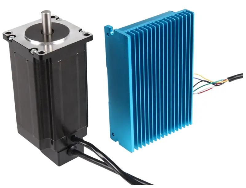
JOY-iT NEMA-23-04CL Nema Closed-Loop Step Motor
GENERAL INFORMATION
Dear customer,
Thank you very much for choosing our product. In the following, we will show you what you need to consider during commissioning and use. Should you unexpectedly encounter any problems during use, please feel free to contact us.
CONNECTIONS
- 2 multi-core cables lead out of the stepper motor.
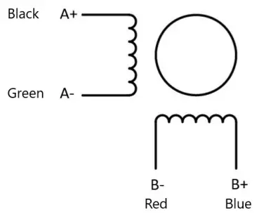
- The 4-core cable belongs to the motor, the cable assignment is as follows:
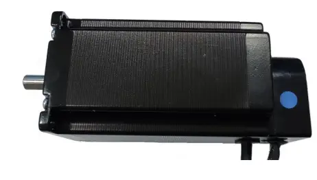
- If your motor was delivered with a blue marking on the side of the encoder housing, as shown in the following picture, the following pin assignment must be used:
| Connection | Color |
| A+ | Black |
| A- | Green |
| B+ | Blue |
| B- | Red |
| Connection | Color |
| A+ | Green |
| A- | Black |
| B+ | Blue |
| B- | Red |
- In addition, an 18 – 70 V DC power supply for the motor must be connected to the motor driver at V+ / V-.
- In addition, a protective grounding can be connected to .
- The 6-core cable belongs to the encoder, the cable assignment is as follows
| Connection | Color |
| EB+ | White |
| EB- | Yellow |
| EA+ | Green |
| EA- | Blue |
| VCC | Red |
| GND | Black |
There is another terminal block on the motor driver, this is for the control signal. The connections have the following functions:
| Connection | Function | Remarks |
| PUL+ | PUL+ and PUL- are the positive and negative termi- nals of the control pulse signal. | 3,3 V ~24 V |
| PUL- | ||
| DIR+ | DIR+ and DIR- are the positive and negative terminals of the directional signal. | |
| DIR- | ||
| ENA+ | ENA+ and ENA- the positive and negative terminals of the enable signal. | |
| ENA- | ||
| ALM+ | ALM+ and ALM- are the positive and negative termi- nals of the alarm output signal. | < 24 V, 40 mA |
| ALM- |
The pin assignment of the RS-232 connection is as follows: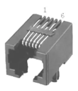
| Pin | Funktion |
| 1 | NC |
| 2 | 5V |
| 3 | TXD |
| 4 | GND |
| 5 | RXD |
| 6 | NC |
DIP-SWITCHES
DIP switches 1 to 4 are used to configure the micro steps of the following dimensions:
| Mikrosteps | SW1 | SW2 | SW3 | SW4 |
| 3600 | ON | ON | ON | ON |
| 800 | OFF | ON | ON | ON |
| 1600 | ON | OFF | ON | ON |
| 3200 | OFF | OFF | ON | ON |
| 6400 | ON | ON | OFF | ON |
| 12800 | OFF | ON | OFF | ON |
| 25600 | ON | OFF | OFF | ON |
| 7200 | OFF | OFF | OFF | ON |
| 1000 | ON | ON | ON | OFF |
| 2000 | OFF | ON | ON | OFF |
| 4000 | ON | OFF | ON | OFF |
| 5000 | OFF | OFF | ON | OFF |
| 8000 | ON | ON | OFF | OFF |
| 10000 | OFF | ON | OFF | OFF |
| 20000 | ON | OFF | OFF | OFF |
| 40000 | OFF | OFF | OFF | OFF |
With the DIP switch 5 (SW5) you can set the direction of rotation of the motor. If the switch is set to ON, it rotates clockwise, if the switch is set to OFF, it rotates counterclockwise. The setting is only accepted after a restart of the unit. DIP switch 6 (SW6) is used to select whether the internal smoothing function for the input pulse signal should be activated. If the switch is set to ON, this means that the smoothing function is enabled, if it is set to OFF, the Function disabled. The setting is only accepted after a restart of the unit. DIP switch 7 (SW7) is used to select the input pulse mode. If the switch is set to ON, the PUL/DIR mode is active, if it is OFF, the CW/CCW mode is active. The setting is only accepted after a restart of the unit. With the DIP-switch 8 (SW8) you can activate or deactivate the step loss detec-tion. If the switch is set to OFF, the step loss detection is activated, if the switch is set to ON, it is deactivated. The setting is only applied after the unit has been restarted.
LED INDICATORS
A green and a red LED are installed on the motor driver to indicate the current status.
| LED status | Drive status | |
| The green LED lights up | Drive not active | |

| The green LED flashes | Drive operates normally |
 | The red and green LEDs light up | Overcurrent |
 | The red LED flashes twice and the green once | Overvoltage |
 | The red LED flashes three times and the green LED once | Incorrect internal driver voltage |
| | The red LED flashes four times and the green LED once | Tracking error exceeds the limit value |
 | The red LED flashes five times and the green LED once | Encoder phase error |
CONTROL SIGNAL CONNECTION
PUL, DIR port: Connection for pulse command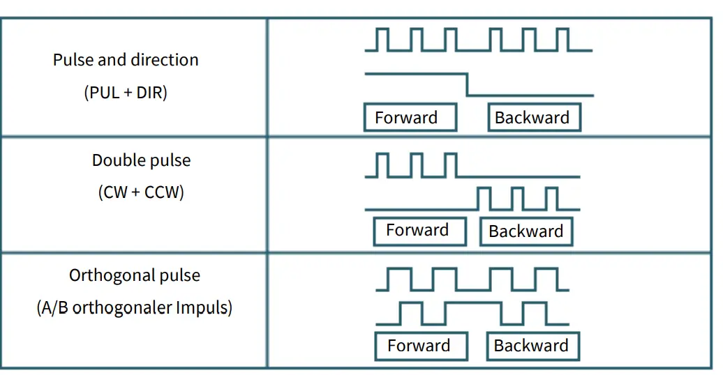
- The standard signal is pulse-shaped.
- The motor driver can receive three types of pulse command signals.
ENA-port: enable/disable
When the standard optocoupler is off, the driver outputs current to the motor. When the internal optocoupler is on, the driver cuts off the current to each pha-se of the motor, so that the motor is in a is free state and cannot react to the step pulse.
If the motor is in the wrong state, the connection enables an automatic switch-off. The level logic of the enable signal can also be set in reverse.
ALM-port: Alarm output
The ALM connector is used to output the driver’s operating status to the exter-nal control circuit. ALM outputs different optocoupler levels when the driver is in the wrong state and in normal operating state.
Control signal wiring example
Connection to open-collector signal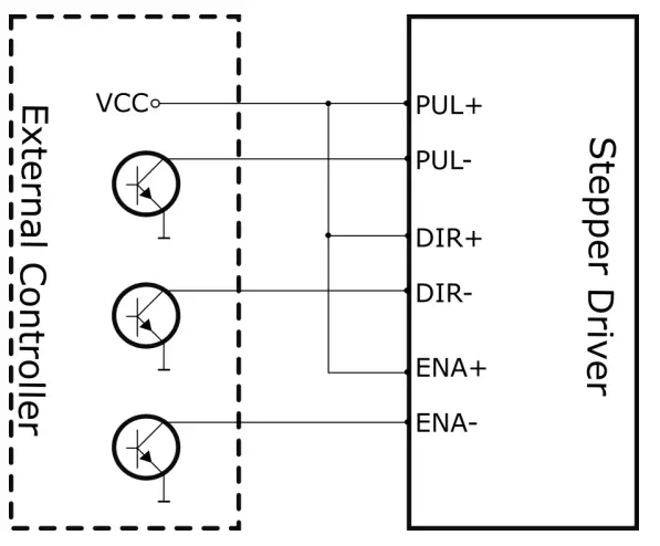
Connection to PNP signal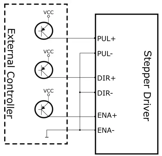
Differential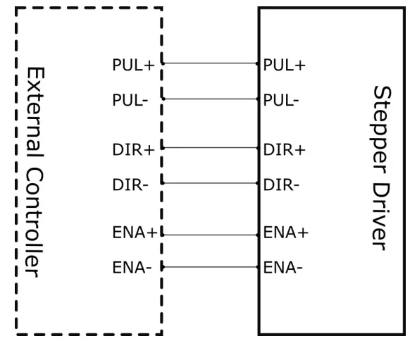
PC SOFTWARE
First steps
- First you need to download the PC software here and then install it on your computer.
- To control your motor driver with the PC software, you need an appropri-ate RJ-11 to SUB-D 9 connection cable.
- When selecting the cable, pay attention to the correct pin assignment. You must connect the RJ-11 plug to your motor driver and the SUB-D plug to a COM port on your PC.
- Now you can start the PC software.
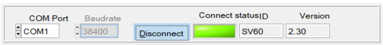
- Now select the COM port to which the driver is connected and press Connect.
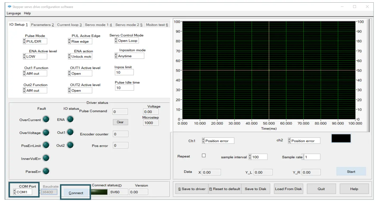
- When the connection has been successfully established, the status indi-cator lights up green. This should look like this.

Driver status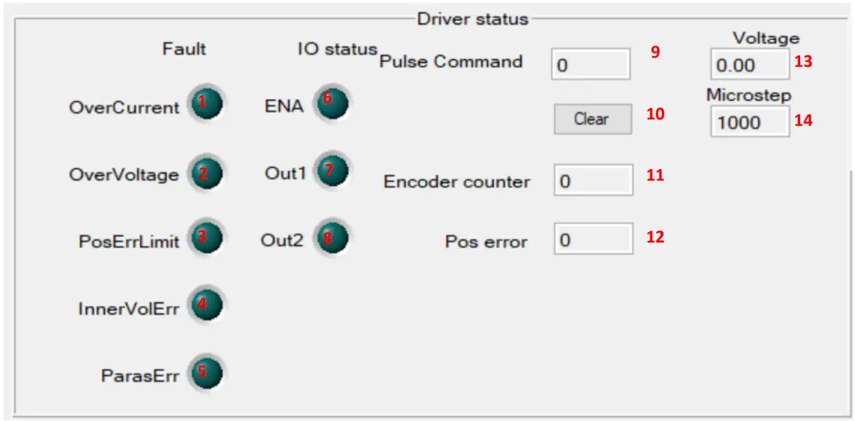
| Number | Function |
| 1 | Lights up in case of overcurrent |
| 2 | Lights up in case of overvoltage |
| 3 | Lights up when the position error limit has been exceeded |
| 4 | Lights up in the event of an internal voltage error |
| 5 | Lights up in the event of a parameter error |
| 6 | Lights up when driver is activated |
| 7 | Lights up when output signal 1 of the motor driver is active. |
| 8 | Lights up when output signal 2 of the motor driver is active. |
| 9 | Indicates the number of pulses |
| 10 | Press to reset |
| 11 | Indicates the number of encoder steps |
| 12 | Indicates the current number of position errors |
| 13 | Indicates the current voltage |
| 14 | Indicates the current microsteps |
IO Setup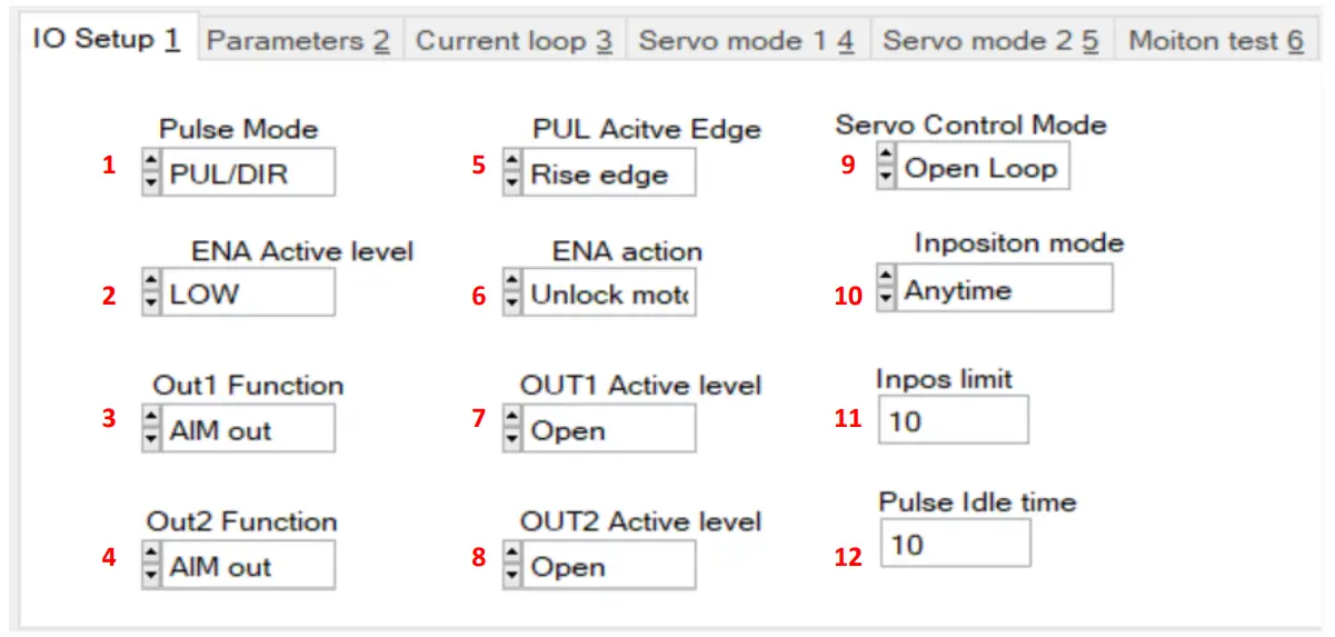
| Number | Function |
| 1 | Setting the pulse mode |
| 2 | Setting the Active Level of the Enable Pin |
| 3 | Setting the function for output1 of the motor driver |
| 4 | Setting the function for output2 of the motor driver |
| 5 | Setting the active PUL edge |
| 6 | Setting the Enable Action |
| 7 | Setting the active OUT1 edge |
| 8 | Setting the active OUT2 edge |
| 9 | Setting the servo control mode |
| 10 | Setting the input mode |
| 11 | Setting the inpos limit |
| 12 | Setting the pulse idle time |
Parameter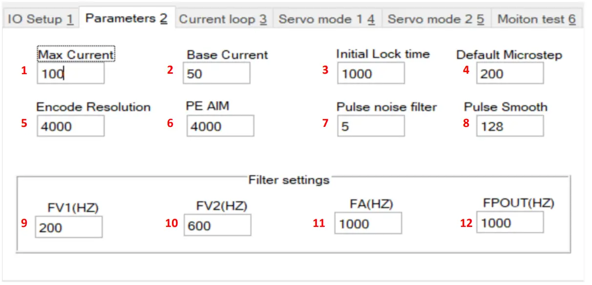
| Number | Function |
| 1 | Setting the maximum current |
| 2 | Setting the base current |
| 3 | Setting the Initial Locking Time |
| 4 | Setting the standard microsteps |
| 5 | Setting the encoder resolution |
| 6 | Setting the permissible step losses |
| 7 | Adjusting the impulse noise filter |
| 8 | Setting the pulse smoothing |
| 9 | Speed feedback filter1 |
| 10 | Speed feedback filter2 |
| 11 | Acceleration feedback filter |
| 12 | Frequency of the output pulse signal |
Current control loop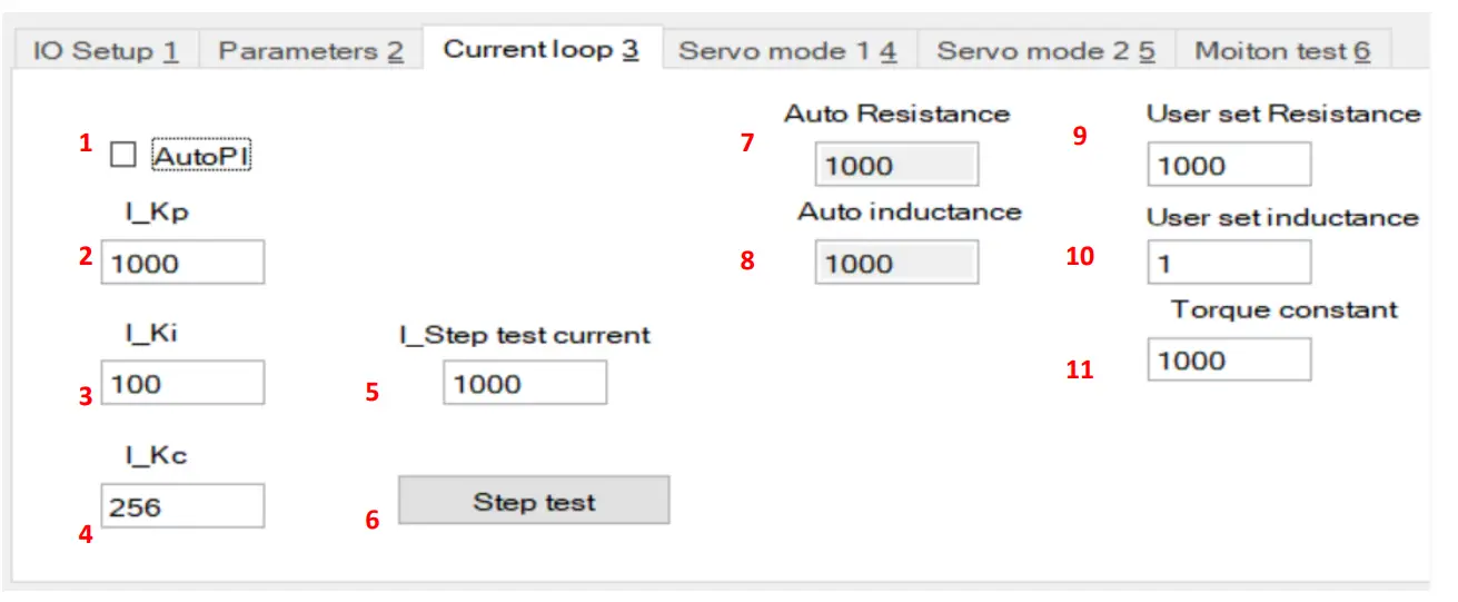
| Number | Function |
| 1 | Activate / deactivate the proportional-integral regulator |
| 2 | Proportional gain PI regulator |
| 3 | Integral gain PI regulator |
| 4 | Gain PI regulator |
| 5 | Setting the current for the step test |
| 6 | Perform a step test |
| 7 | Shows the phase resistance in mΩ |
| 8 | Shows the phase inductance in mH |
| 9 | Setting the resistance |
| 10 | Setting the induction |
| 11 | Adjusting the torque |
Servo Mode 1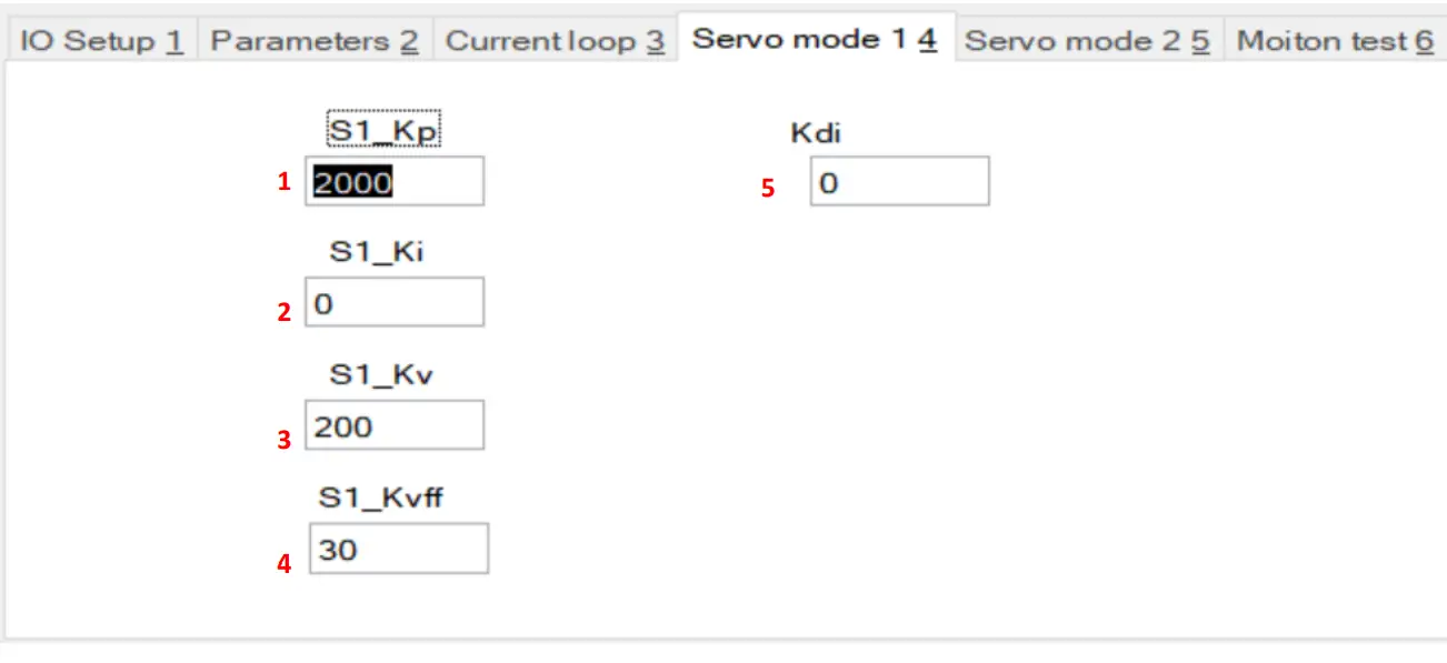
| Number | Function |
| 1 | Setting the Proportional Gain |
| 2 | Setting the integral gain |
| 3 | Damping factor |
| 4 | Setting the speed feedback |
| 5 | Setting the damping |
Servo Mode 2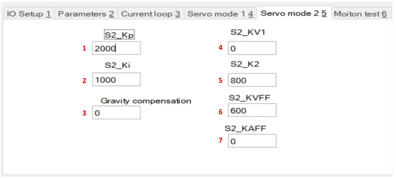
| Number | Function |
| 1 | Setting the proportional gain |
| 2 | Setting the integral gain |
| 3 | Setting the gravity compensation |
| 4 | Speed feedback 1 |
| 5 | Speed feedback 2 |
| 6 | Speed Forward Gain |
| 7 | Acceleration Forward Gain |
Motion test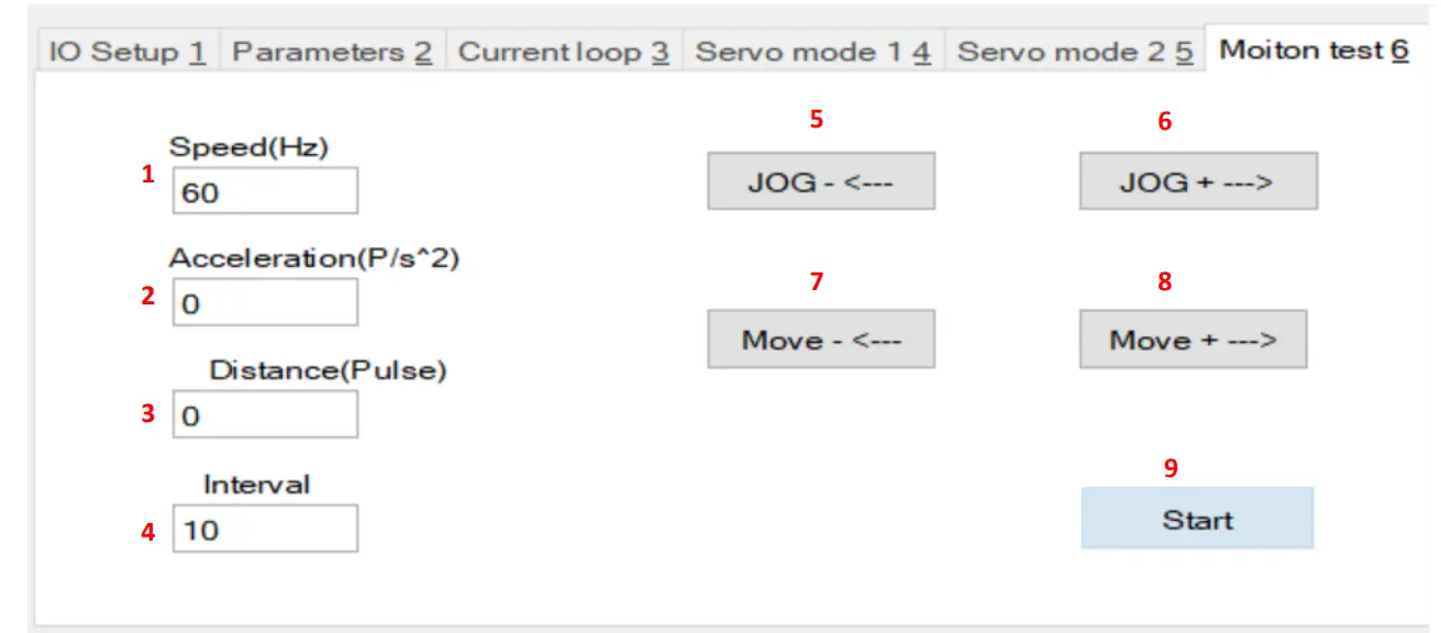
| Number | Function |
| 1 | Setting the speed |
| 2 | Setting the acceleration |
| 3 | Setting the distance |
| 4 | Setting the delay between repetitions |
| 5 | Press and hold to move backwards |
| 6 | Press and hold to move forward |
| 7 | Press to move the set distance backwards |
| 8 | Press to move the set distance forward |
| 9 | Press to start the test mode with the set parameters |
Diagram display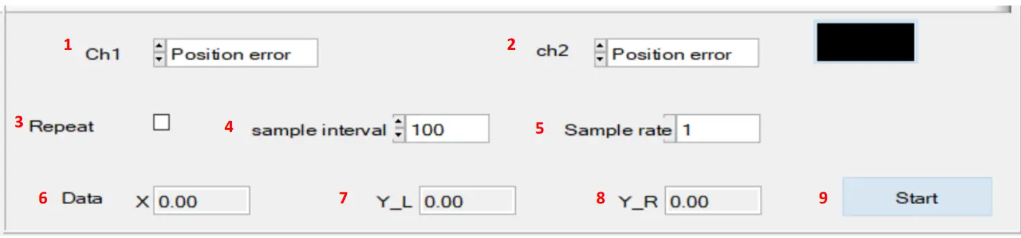
| Number | Function |
| 1 | Setting the CH1 graph |
| 2 | Setting the CH2 graph |
| 3 | Enable/disable the repeat function |
| 4 | Setting the sampling interval |
| 5 | Setting the sampling rate |
| 6 | Indicates position of the cursor on the X-axis |
| 7 | Indicates position of the cursor on the left Y-axis |
| 8 | Indicates position of the cursor on the right Y-axis |
| 9 | Start or stop the diagram display |
ADDITIONAL INFORMATION
Our information and take-back obligations according to the Electrical and Electronic Equipment Act (ElektroG)
Symbol on electrical and electronic equipment:
This crossed-out dustbin means that electrical and electronic appliances do not belong in the household waste. You must return the old appliances to a collection point.
Before handing over waste batteries and accumulators that are not en-closed by waste equipment must be separated from it.
Return options:
As an end user, you can return your old device (which essentially fulfils the same function as the new device purchased from us) free of charge for disposal when you purchase a new device. Small appliances with no external dimensions greater than 25 cm can be disposed of in normal household quantities independently of the pur-chase of a new appliance.
Possibility of return at our company location during opening hours: SIMAC Electronics GmbH, Pascalstr. 8, D-47506 Neukirchen-Vluyn, Germa-ny
Possibility of return in your area:
We will send you a parcel stamp with which you can return the device to us free of charge. Please contact us by email at [email protected] or by telephone.
Information on packaging:
If you do not have suitable packaging material or do not wish to use your own, please contact us and we will send you suitable packaging.
SUPPORT
If there are still any issues pending or problems arising after your purcha-se, we will support you by e-mail, telephone and with our ticket support system.
- Email: [email protected]
- Ticket system: http://support.joy-it.net
- Telephone: +49 (0)2845 9360-50 (10-17 o‘clock)
- For further information please visit our website:
- www.joy-it.net
- Published: 07.10.2022


