![]() 24V AC or DC Powered Isolating Signal Converter
24V AC or DC Powered Isolating Signal Converter
User Manual
ISKCON-6 24V AC or DC Powered Isolating Signal Converter
Whilst every effort has been taken to ensure the accuracy of this document, we accept no responsibility for damage, injury, loss, or expense resulting from errors or omissions, and reserve the right of amendment without notice. This document may not be reproduced in any way without the prior written permission of the company.
INTRODUCTION
1.1 Hardware Features
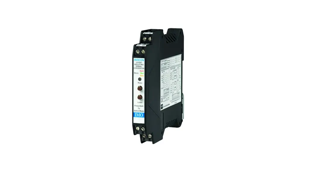
The ISO-6 is a universal input Isolating Signal Converter. It can accept virtually every type of analog input signal from millivolts to 40Vdc, mA, thermocouples, RTDs, etc. It also produces 3 types of analog output; voltage, mA source, or mA sink.
The unit can be powered by any DC voltage between 12 and 36Vdc or 12 and 32Vac. For mains AC voltage the ISOCON-3 is available which can be powered from any supply from 90Vac to 264Vac at 50 or 60Hz. The instrument is packaged in a very compact 12.5mm wide enclosure which can be mounted on a standard TS35 DIN rail. The unit can also be equipped with 1 digital output which can be either a relay or an open collector output, or a second analog output (see DUALCON-6). Note, units with the above options are housed in a 17.5mm wide box.
1.1.1 Isolation Details
The ISKCON-6 has full 3 port isolation of 1000V between the Input Stage, Output Stage, and Power Supply for functional reasons.
UNPACKING
The instrument should be carefully inspected for signs of damage that may have occurred in transit. In the unlikely case that damage has been sustained, DO NOT use the instrument, but please retain all packaging for our inspection and contact your supplier immediately.
The instrument comes with the following items as standard:
1Isocon-6 Isolating Signal Converter
1Isocon-6 User Guide
If the instrument has been factory configured the input and output details will be listed on the Serial number label on the side of the unit. If this label is blank then the unit will be set to its default configuration which is 4-20mA input and 420mA source output. Please check that the details on the side label are correct, especially the power supply voltage. If re-configuration is required please refer to Section 4 of this manual
CONNECTIONS
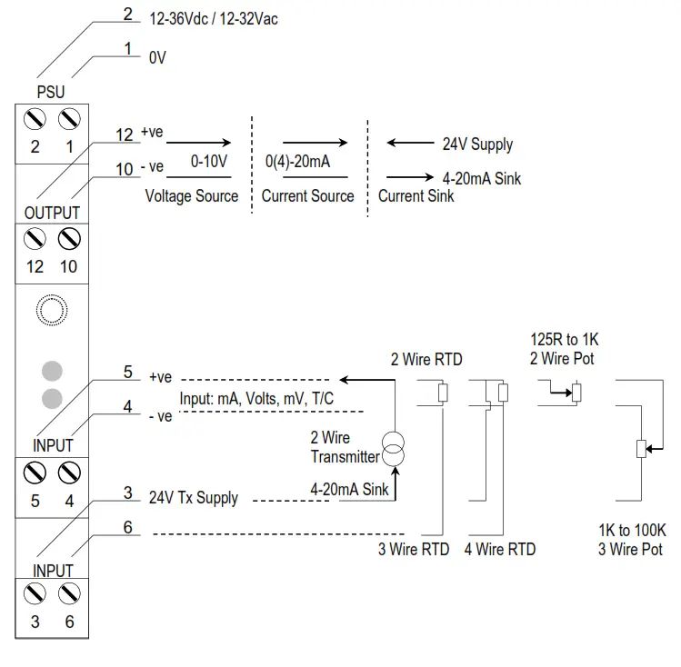
The ISO is housed in a compact DIN rail mounting enclosure, with 8 terminals, arranged in 4 rows of 2 terminals. Two rows are at the top of the front panel and 2 rows are at the bottom. All the sensor input terminals are on the bottom rows and the power supply and analog outputs are on the top terminals. The diagram below shows how to connect all the different input, output, and power supply types.
CONFIGURING THE ISKCON
![]() WARNING! DO NOT OPEN THE UNIT OR ADJUST SWITCHES WITH THE POWER SUPPLY, INPUT, OR OUTPUT CONNECTED
WARNING! DO NOT OPEN THE UNIT OR ADJUST SWITCHES WITH THE POWER SUPPLY, INPUT, OR OUTPUT CONNECTED
The ISO is an extremely versatile device that can support many different types of input. The unit is configured by turning the power off, selecting the internal switch settings required, and turning the power back on.
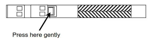
To open the Isocon, 2 catches just below the outer terminal blocks must be pushed in gently, one at a time. The front of the case can then be pulled and the unit will come out of the box.
 There are 3 switch banks, S1, S2, and S3, located inside the ISOCON as shown below:
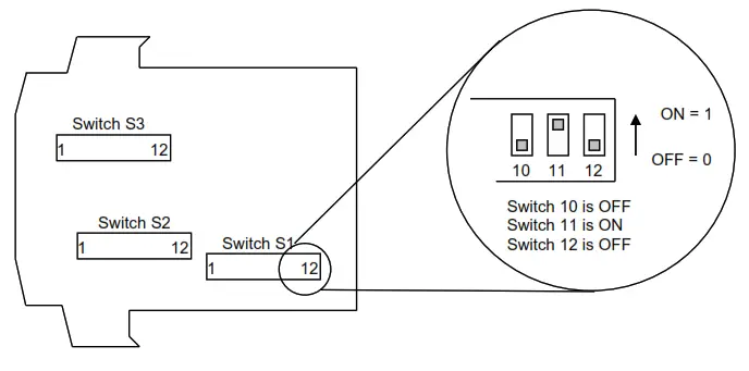
Switch S1 and S2 configure the input type and range, and switch S3 configures the output type, range, and a few additional functions. The switch settings are explained in the next few pages. The diagrams refer to switch positions 0 and 1, with 0 being OFF and 1 being ON. This is illustrated in the picture above.
4.1.1 Voltage Input:
Select the range from the table below and set Switch S1 to the required values.
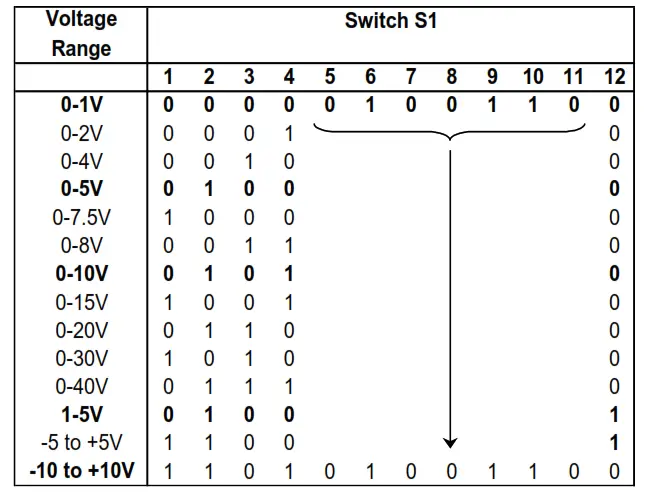
Then select the required setting from the table below for switch S2
| Voltage Range | Switch S2 |
| 0-30V & 0-40V Ranges | 1 2 3 4 5 6 7 8 9 10 11 12 |
| 0 0 1 1 0 0 1 1 0 0 0 0 | |
| All other Ranges Listed Above | 0 0 1 0 1 0 1 0 0 0 0 0 |
![]() WARNING!
WARNING!
DO NOT OPEN THE UNIT OR ADJUST SWITCHES WITH THE POWER SUPPLY, INPUT, OR OUTPUT CONNECTED
Please note that PC Software is available to provide information on switch settings for your input and output requirements.
4.1.2 Current Input
Select the range from the table below and set Switch S1 to the required values.
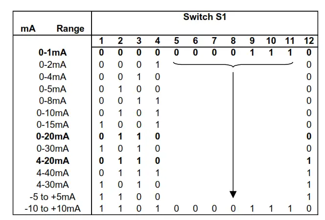
Then select the required setting from the table below for switch S2
| mA Range | Switch S2 |
| Using Internal 24VTx Supply for 4 to 20mA | 1 2 3 4 5 6 7 8 9 10 11 12 |
| 1 1 0 1 0 0 1 1 0 0 1 0 | |
| Unipolar Ranges (e.g. 0-20mA, 4-20mA) | 1 1 0 0 0 0 1 1 0 0 0 0 |
| Bipolar Ranges (e.g. -10 to +10mA) | 1 1 0 0 1 0 1 0 0 0 0 0 |
![]() WARNING!
WARNING!
DO NOT OPEN THE UNIT OR ADJUST SWITCHES WITH THE POWER SUPPLY, INPUT OR OUTPUT CONNECTED
Please note that PC Software is available to provide information on switch settings for your input and output requirements.
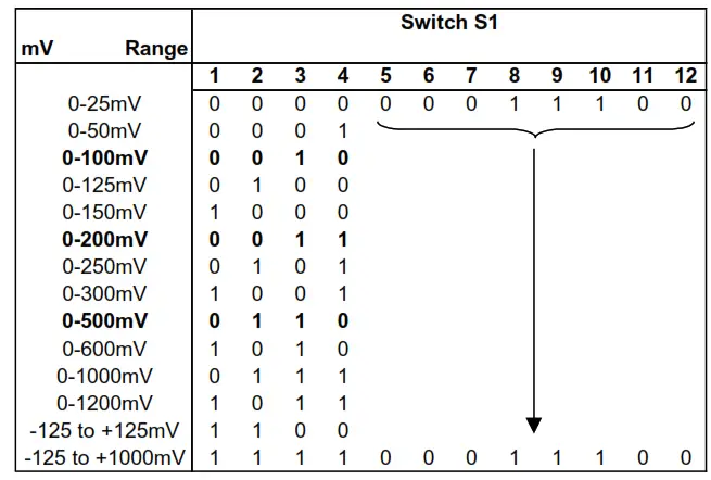
1.3 Millivolt (mV) Input
Select the range from the table below and set Switch S1 to the required values.
| Voltage Range | Switch S2 |
| All UnipolarRanges (e.g. 0-500mV) | 1 2 3 4 5 6 7 8 9 10 11 12 |
| 0 1 0 0 0 0 1 1 0 0 0 0 | |
| Bipolar Ranges e.g.-125 to +125mV) | 0 1 0 0 1 0 1 0 0 0 0 0 |
![]() WARNING!
WARNING!
DO NOT OPEN THE UNIT OR ADJUST SWITCHES WITH THE POWER SUPPLY, INPUT, OR OUTPUT CONNECTED
Please note that PC Software is available to provide information on switch settings for your input and output requirements.
4.1.4 Potentiometer Input
Select the range from the table below and set Switch S1 to the required values.
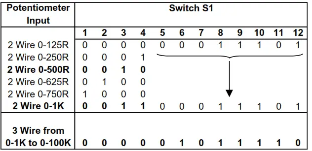 Then select the required setting from the table below for switch S2
| PotentiometerInput | Switch S2 |
| 2 WirePotentiometer | 1 2 3 4 5 6 7 8 9 10 11 12 |
| 0 1 0 0 1 0 0 1 0 0 0 1 | |
| 3 Wire Potentiometer | 0 0 1 1 0 0 1 1 0 0 1 0 |
![]() WARNING!
WARNING!
DO NOT OPEN THE UNIT OR ADJUST SWITCHES WITH THE POWER SUPPLY, INPUT OR OUTPUT CONNECTED
Please note that PC Software is available to provide information on switch settings for your input and output requirements.
4.1.5 Thermocouple Input
Select the range from the table below and set Switch S1 to the required values.
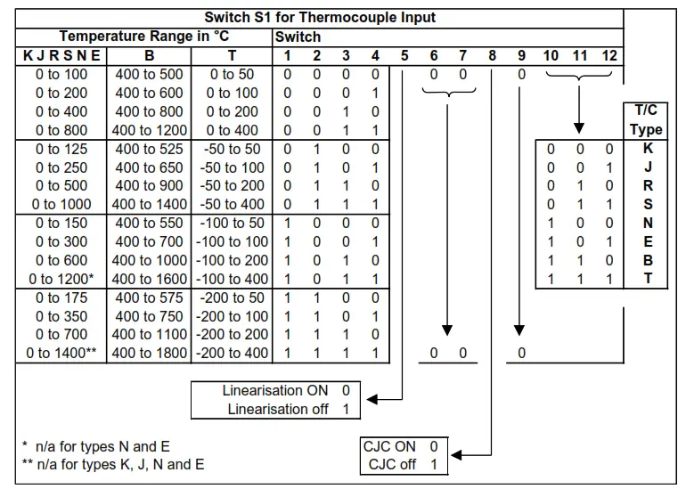 Then select the required setting from the table below for switch S2
| Thermocouple | Switch S2 |
| All Ranges | 1 2 3 4 5 6 7 8 9 10 11 12 |
| 0 1 0 0 1 1 1 0 0 0 0 0 |
![]() WARNING!
WARNING!
DO NOT OPEN THE UNIT OR ADJUST SWITCHES WITH THE POWER SUPPLY, INPUT, OR OUTPUT CONNECTED
Please note that PC Software is available to provide information on switch settings for your input and output requirements.
4.1.6 RTD Input
Select the range from the table below and set Switch S1 to the required values.
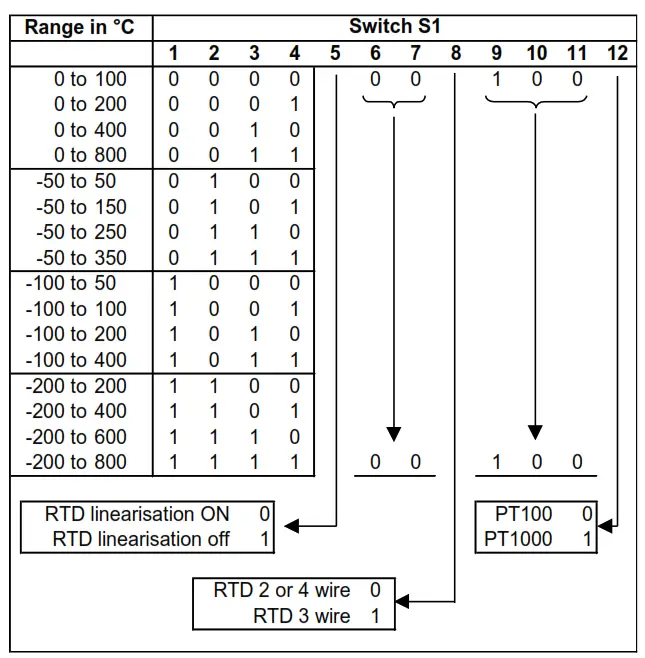
And then select the required setting from the table below for switch S2
| RTD | Switch S2 |
| 2 Wire RTD | 1 2 3 4 5 6 7 8 9 10 11 12 |
| 0 1 0 0 1 0 0 1 0 0 0 1 | |
| 3 Wire RTD | 0 1 0 0 0 0 0 0 1 0 0 1 |
| 4 Wire RTD | 0 1 0 0 0 0 0 1 0 1 0 0 |
![]() WARNING!DO NOT OPEN THE UNIT OR ADJUST SWITCHES WITH THE POWER SUPPLY, INPUT OR OUTPUT CONNECTED.
WARNING!DO NOT OPEN THE UNIT OR ADJUST SWITCHES WITH THE POWER SUPPLY, INPUT OR OUTPUT CONNECTED.
Please note that PC Software is available to provide information on switch settings for your input and output requirements.
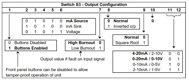
4.1.7 Output Configuration
Select the range from the table below and set Switch S3 to the required values.
Examples:
| Switch S3 Examples | |
| 1 2 3 4 5 6 7 8 9 10 11 12 | |
| 4-20mA Source | 1 0 1 0 1 0 0 0 0 0 0 0 |
| 0-20mA Source | 1 0 1 0 1 0 0 0 0 0 0 1 |
| 0-10V | 1 0 1 0 1 1 0 0 0 0 0 1 |
| 4-20mA Sink | 1 1 0 1 0 0 0 0 0 0 0 0 |
![]() WARNING! DO NOT OPEN THE UNIT OR ADJUST SWITCHES WITH THE POWER SUPPLY, INPUT OR OUTPUT CONNECTED’
WARNING! DO NOT OPEN THE UNIT OR ADJUST SWITCHES WITH THE POWER SUPPLY, INPUT OR OUTPUT CONNECTED’
Please note that PC Software is available to provide information on switch settings for your input and output requirements.
CALIBRATING THE ISKCON
When the unit is shipped the ISOCON will be calibrated for the input and output types and ranges noted on the side label. If this label is blank then the unit will be calibrated or 4-20mA input and 4-20mA source output. If the unit is re-ranged by the user it is necessary to re-calibrate the unit to obtain the maximum accuracy. The calibration is achieved by using both switches on the front panel to select the zero or span input and then using the switches as raise/lower buttons to adjust the output to the value required.
The mode the unit is in is indicated by the color of the LED:
| Green | Normal Operation |
| Red | Span Adjust |
| Yellow | Zero Adjust |
The setting of the zero and span points is non-interactive, so each point needs only be set once. A typical calibration sequence would be as follows:
| LED Colour | Mode | Action |
| Green | Normal | Apply full-scale input. Press and release both buttons together to enter span mode |
| RED | Span Adjust | Press the raise / lower buttons to adjust the output value Press and release both buttons together to return to normal mode |
| Green | Normal | Apply zero scale input Press and release both buttons together to enter zero mode |
| YELLOW | Zero Adjust | Press the raise / lower buttons to adjust the output value Press and release both buttons together to return to normal mode |
| Green | Normal | Use product |
The unit is now calibrated and ready for use.
Note: The unit will retain the new settings on power down.
When the unit is used to convert a thermocouple input it is important when calibrating to ensure that the thermocouple simulator employed is switched to automatic cold junction compensation and is at the same ambient temperature as the ISKCON. Note that this is not always easy to achieve, especially if the ISOCON is mounted in a warm cabinet. An alternative method is to use an ice-point reference and an mV source.
INSTALLATION
The ISOCON’s input and output circuits are classed as Separated Extra Low Voltage (SELV). This means that they must not be externally connected to voltages exceeding 30V ac or 60V dc, nor do they generate voltages above these limits internally. Where a higher voltage input is required a specially designed DIVIDER unit can be used to condition the input signal before connection to the process input terminals. The ISKCON unit clips directly onto the ‘Top Hat’ (TS35) symmetrical DIN rail. Ideally, the mounting orientation should be vertical, with the power supply situated on the top face to minimize temperature rise. Good airflow around the unit will maximize the reliability of the instrument. The use of bootlace ferrules is recommended for wiring terminations. Do not exceed the terminal torque rating of 0.4 Nm – use an appropriate screwdriver. The unit can be removed from the DIN rail by sliding a small screwdriver into the slot at the rear of the enclosure on the lower face and gently levering the metal clip, whilst lifting the unit from the rail.
TROUBLESHOOTING
The ISO has some built-in self-diagnostic functions. If the LED on the front panel is flashing then the fault mode can be found by counting the number of flashes between gaps and using the table below to locate the problem.
| No of Flashes | Nature of Fault | Corrective Action |
| 0 (Green On) | Unit Working – no suspected fault | Check Wiring and switch settings |
| 2,3,4,5,6,8,9, 10,11,12 green | Hardware Error, extreme noise, poor supply | Switch off the unit, check the switch settings, and wiring, and retry. If still faulty please contact the supplier |
| 7 green | RTD /Thermocouple burnout | Repair RTD, T/C, or wiring |
| 3 or 4 Red | The span point is too close to the zero point | Change input span value and retry |
| 3 or 4 Yellow | Zero point is too close to spawn point | Change input zero value and retry |
| No LED | Power Failure | Check supply lines and voltage |
7.1 Incorrect Reading
- Check that Unit is configured for the correct Sensor
- Check that Input Scaling is as required.
- Check that Linearisation has not been set incorrectly.
- Check that Thermocouples have correct compensation cables and polarity.
- Check that RTD is set for the correct option 2, 3, or 4 Wire.
- Check that RTD leads are connected to appropriate terminal pins.
7.2 Sensor Failure
- Check that the sensor wiring is correct.
- Check Thermocouple polarity.
- Check that all RTD leads are connected to the correct terminals.
- Check that the ISKCON is configured for the correct sensor.
- Check that the applied voltage is not out of range.
- Check that the applied current is not out of range.
- Check that the applied millivoltage is out of range.
SPECIFICATIONS ( @ 25°C)
| Operating Temperature | 0 to 55 °C |
| Operating Altitude | Sea Level to 2000m |
| Humidity | 0-90% RH |
| Power Requirements | |
| DC Supply | 12 to 36Vdc |
| AC Supply | 12 to 32Vac |
| Current Consumption | 55mA @ 24Vdc (20mA in & out) |
| Transmitter Power Supply | 22V to 29V @ up to 24mA |
| Calibration accuracy | ±0.05% full scale |
| Linearity | ±0.05% full scale |
| Temperature Stability | 50ppm / °C |
| Input Impedance: | |
| Current Input | 15 ohms |
| Voltage Input | 1 Mohm |
| Millivolt Input | Greater Than 10 Mohm |
| Thermocouple Burn Out Current: | 500nA Nominal |
| Cold junction compensation accuracy | ±0.5°C over the operating range |
| Maximum Voltage Output | 11.5 V into a minimum of 7Kohm |
| Maximum Current Output | 23.0 mA into a maximum of 1Kohm |
| Time Response (90% of a step change | e): 50ms ± 10ms |
| The unit has full 3 port Isolation to 1kV between Power Supply, Input, and Output. | |
| Dimensions | 114.5 mm x 99mm x 12.5mm (H x D x W) |
| Mounting | DIN Rail TS35 |
| Connections | Screw Clamp with pressure plate |
| Conductor Size | 0.5 to 4.0 mm |
| Insulation Stripping | 12 mm |
| Maximum Terminal Torque | 0.4 Nm |
| Weight | Approx. 95g |
| EMC Emissions | EN50081-1:1992 |
| EMC Immunity | EN61010-1:1993 |
| LVD Standards | II |
| Installation Category (IEC 664) | 2 |
| Pollution Degree (EN61010-1:1993)Equipment Class (IEC 536) | II |
![]()


