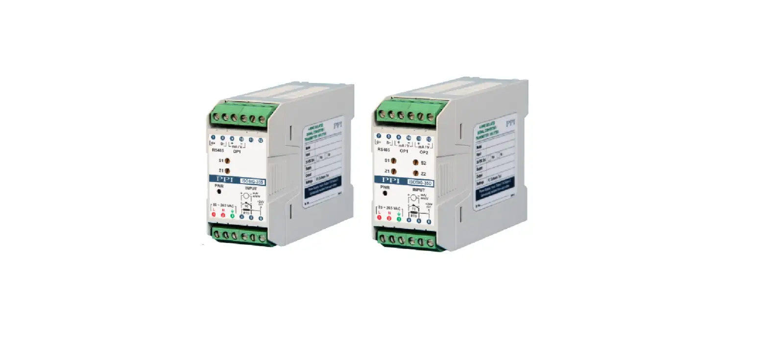
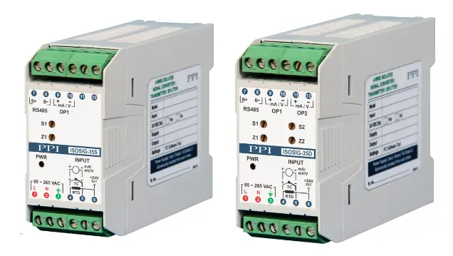
PPI ISOSIG-35S Programmable 4-Wire Isolated Signal Converter
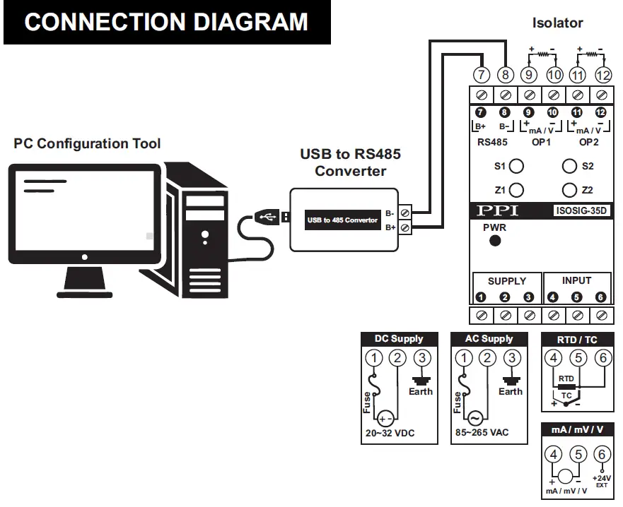
CONNECTION DIAGRAM
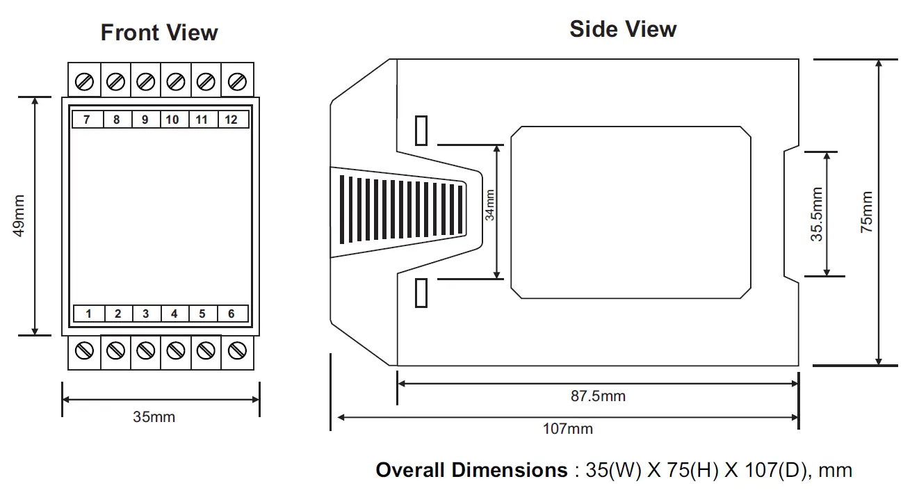
DIMENSIONS (mm)
INPUT WIRING DIAGRAM
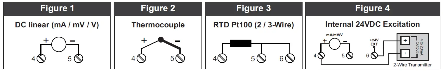
DC linear (mA / mV / V)
Connect Signal Positive to terminal marked (+) & Negative to terminal marked (-) as shown in Figure 1.
Thermocouple
Connect Thermocouple Positive to terminal marked (+) & Negative to terminal marked (-) as shown in Figure 2 .
RTD Pt100, 3-Wire / 2-Wire
For 3-Wire configuration, connect single leaded end of RTD bulb to terminal 4 and the double leaded ends to terminal 5 and 6 (interchangeable) as shown in Figure 3. For 2-Wire configuration, connect RTD bulb across terminals 4 & 5 (interchangeable).
2-Wire Loop Powered Transmitter connection using Internal 24VDC Excitation(Optional)
Power 2-wire Transmitter through terminal marked (24V EXT). Connect the Output of 2-Wire Transmitter to Terminal marked (+). Leave terminal marked (-) unconnected as shown in Figure 4.
OUTPUT-1 & OUTPUT-2 WIRING DIAGRAM
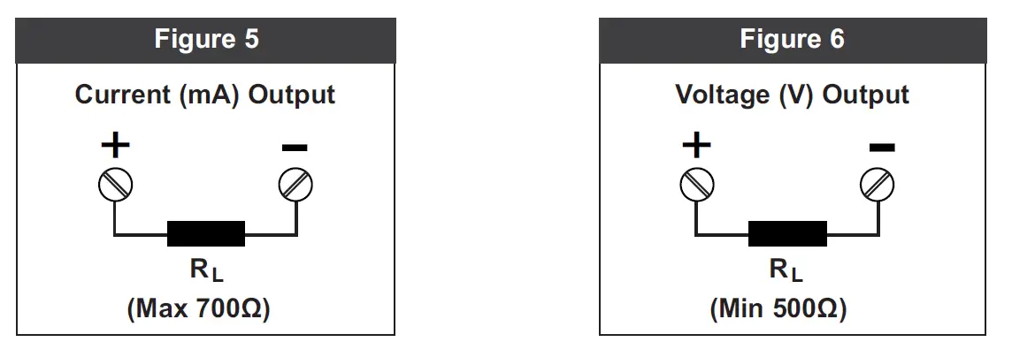
DC linear (mA / V)
Connect Signal Positive to terminal marked (+) & Negative to terminal marked (-) as shown in Figure 5 & Figure 6.


