gearmo RS-232 Passive Opto-Isolated Interface Converter
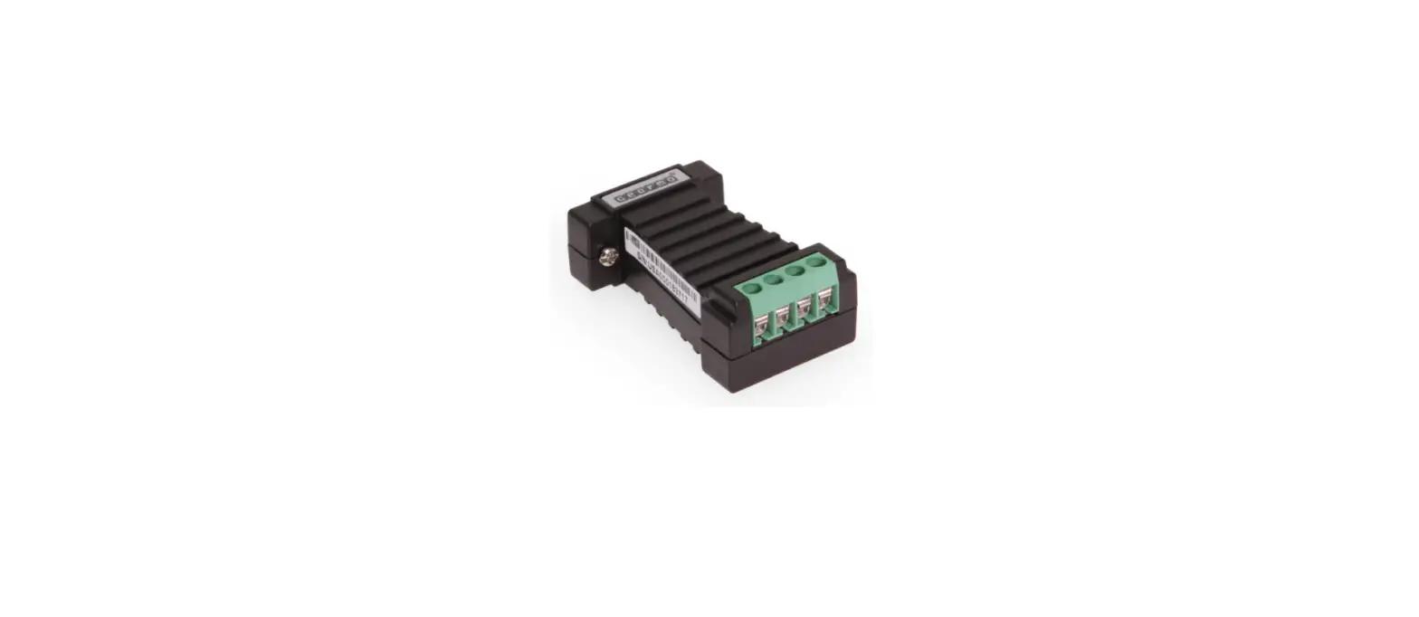
RS-232/RS-485/RS-422 Passive Opto-Isolated Interface Converter Model No. GM-10127-B
General
GM-10127-B Passive Opto-Isolated Interface Convert er, which is RS-232C, RS-422 and RS-485 compatible, can convert single-ended RS-232 signals to balanced differential RS-422 or RS-485 signals. The built-in optoelectronic isolator can provide isolation voltage up to 2500 Vrms. A fast-reacted transient voltage suppressor is equipped and designed to protect the RS-422/RS-485 interface. The currently advanced transient voltage suppressor (TVS) is adopted. The TVS tube is under a high impedance state in normal conditions, but if both ends of the TVS tube are experiencing a transient high energy impact, the TVS tube can reduce impedance on both sides at a very high speed and absorb a big current so that the voltage on both sides can be suppressed to a preset value, thus protecting the rear circuit elements from damage caused by the transient high voltage impact. This TVS protector can effectively suppress lightning and ESD, provide 600 W of lightning surge protection power for each wire, and protect against surge voltage and transient voltage on the lines due to various reasons. The extremely small inter-electrode capacitance ensures high-speed transmission of RS-422/RS-485 interface. The RS-232 interface is connected to a compatible RS-232C standard port through the connector with a DB9 female PIN while the RS-422 and RS-485 ports serve as the output ports through the 6-pin binding post. The converter has an internal automatic zero-delayed transmitting, receiving, and conversion function and a unique I/O circuit for automatic control of data stream direction. Conversion with FDX mode (RS-422) or HDX mode (RS-485) can be achieved without either the need of handshaking signals (such as RTS, DTR) or the setup of a jumper. This product is plug-and-play to ensure compatibility with all existing communication software and interface hardware without the need to modify the software for the previous RS-232 based working mode. The GM-10127-B Passive Opto-Isolated Interface Converter can provide reliable connection by point-to-point or point-to-multipoint communication. For point-to-multipoint communication, each converter can be connected to thirty-two RS-422 or RS-485 interface devices. The converter has a data communication rate up to 300 – 115.2 Kbps and supports communication and conversion from RS-232 to RS-422 as well as from RS-232 to RS-485.
Performance Parameters
- Features of interface: The interface is compatible with RS-232C, RS-485/RS-422 of EIA/TIA.
- Electrical interface: RS-232 is connected to a connector with DB9 (female) while RS-422/RS-485 interface serves as an output terminal through a 6-pin binding post.
- Protection level: 15KV ESD protection for RS-232 and 600W lightning surge protection for RS-422, RS-485 interfaces
- Isolation level: Isolation voltage up to 2500 Vrms, 500 DC continuous
- Working mode: Asynchronous HDX or FDX
- Transmission medium: Twisted-pair or shielded wire
- Transmission rate: 115.2 Kbps ~ 300 m
- Overall dimensions: 61 mm x 41 mm x 21 mm
- Operating environment: -40 ~ 85 , 5% ~95% RH
Connector and Signal
RS-232C PIN configuration
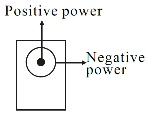
| DB9 Female (PIN) | Positive powerRS-232C Interface Signal |
| 1 | PGND |
| 2 | Transmit Data SOUT (TXD) |
| 3 | Receive Data SIN (RXD) |
| 4 | Data Terminal Ready DTR |
| 5 | Signal Ground GND |
| 6 | Data Set Ready DSR |
| 7 | Request To Send RTS |
| 8 | Clear To Send CTS |
| 9 | Ring Indicate RI |
PIN configuration for RS-485/RS-422 output signals and connection terminal
| 6-pin Connection Terminal | Output Signal | RS-422 FDX Connection | RS-485 HDX Connection |
| 1 | T/R+ | Transmitting (A+) | RS-485(A+) |
| 2 | T/R- | Transmitting (B-) | RS-485(B-) |
| 3 | RXD+ | Receiving (A+) | N/C |
| 4 | RXD- | Receiving (B-) | N/C |
| 5 | SGND | SGND wire | SGND wire |
| 6 | SGND | SGND wire | SGND wire |
Hardware Installation and Application
Prior to the installation of GM-10127-B Passive Opto-Isolated Interface Converter, please read this User’s Manual carefully. Connect this product to the RS-232 port. This product adopts universal DB9 connector as the input end and 6-pin binding post as the output end. RS-485 or RS-422 communication can be automatically realized without the setup of a jumper and the twisted-pair or shielded wire may be used, making it simple for connection and dismantle. In this product, T/R+T/R- = transmitting; +/ – = receiving; RXD+/RXD-= receiving +/ -; and SGND = common earth wire. Point-to-point/point-to-multipoint/HDX communication is connected to T/R+ and T/R- while Point-to-point/point-to-multipoint/FDX communicationis connected to T/R+, T/R-, RXD+, RXD-. The GM-10127-B Passive Opto-Isolated Interface Converter supports the following four communication modes:s:
- Point-to-point/four-wire FDX
- Point-to-multipoint/four-wire FDX
- Point-to-point/two-wire HDX
- Point-to-multipoint/two-wire HDX
Communication Connection Diagram
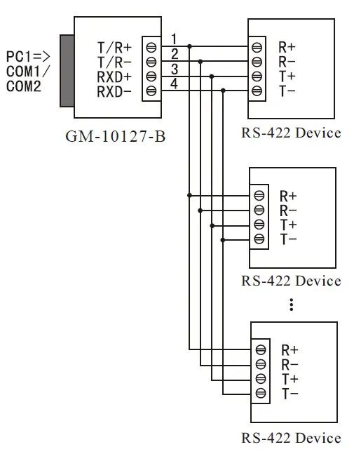
Conversion from RS-232 to RS-422
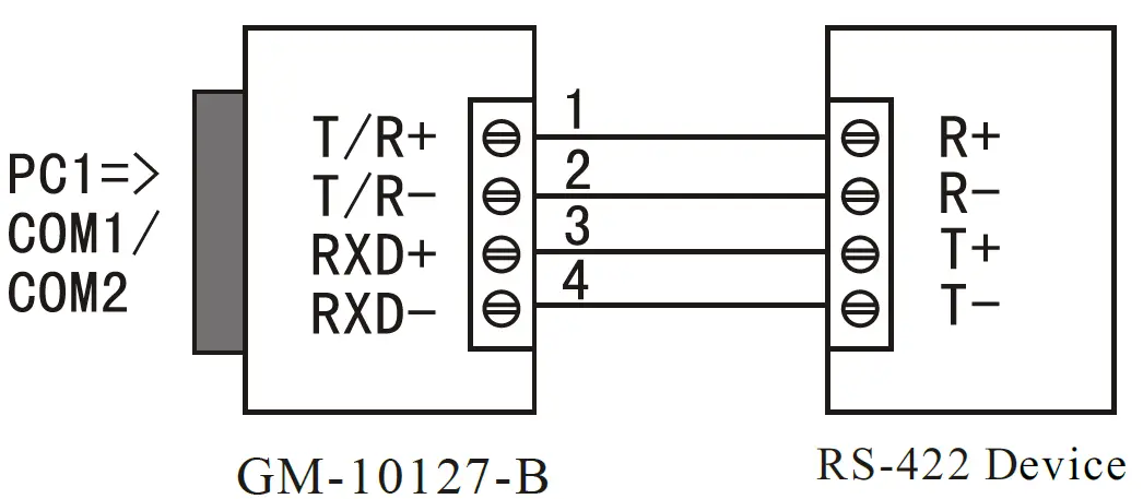
RS-422 point-to-multipoint/four-wire FDX
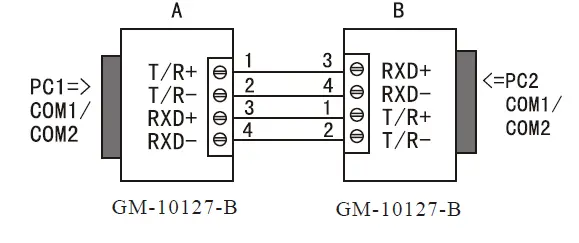
Full-duplex communication connection between GM-10127-B interface converters
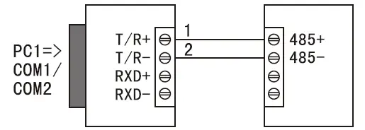
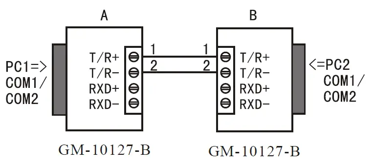
Conversion from RS-232 to RS-485
RS-485 point-to-point/two-wire FDX communication
RS-485 point-to-multipoint/two-wire FDX
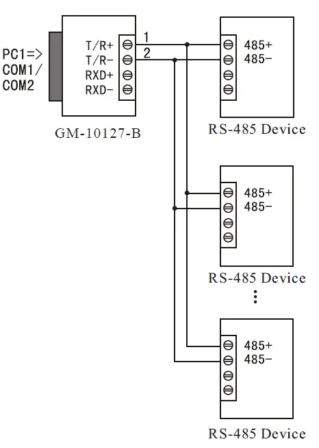
Half-duplex communication connection between GM-10127-B interface converters
Fault and Troubleshooting
- Failure in data communication
- A. Check whether RS-232 port is wired correctly.
- B. Check whether RS-485/RS-422 output interface is wired correctly.
- C. Check whether the connection terminal is connected properly.
- Data loss or error
Check whether data rate and format are consistent at both ends of data communication device.


