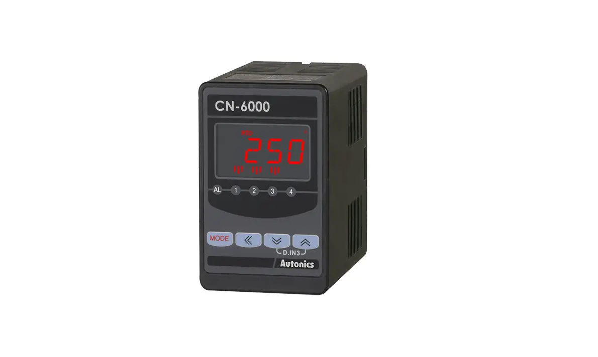
Autonics CN-6000 Series Isolated Converters Instruction Manual
Thank you for choosing our Autonics product.
Read and understand the instruction manual and manual thoroughly before using the product.
For your safety, read and follow the below safety considerations before using.
For your safety, read and follow the considerations written in the instruction manual, other manuals and Autonics website.
Keep this instruction manual in a place where you can find easily.
The specifications, dimensions, etc. are subject to change without notice for product improvement. Some models may be discontinued without notice.
Follow Autonics website for the latest information.
Safety Considerations
- Observe all ‘Safety Considerations’ for safe and proper operation to avoid hazards.
 symbol indicates caution due to special circumstances in which hazards may occur.
 Warning: Failure to follow instructions may result in serious injury or death.
- Fail-safe device must be installed when using the unit with machinery that may cause serious injury or substantial economic loss. (e.g. nuclear power control, medical equipment, ships, vehicles, railways, aircraft, combustion apparatus, safety equipment, crime / disaster prevention devices, etc.)
Failure to follow this instruction may result in personal injury, economic loss or fire. - Do not use the unit in the place where flammable / explosive / corrosive gas, high humidity, direct sunlight, radiant heat, vibration, impact or salinity may be present.
Failure to follow this instruction may result in explosion or fire. - Install on a device panel to use.
Failure to follow this instruction may result in fire or electric shock. - Do not connect, repair, or inspect the unit while connected to a power source.
Failure to follow this instruction may result in electric shock. - Do not disassemble or modify the unit.
Failure to follow this instruction may result in fire or electric shock. - Check ‘Connections’ before wiring.
Failure to follow this instruction may result in fire
Caution: Failure to follow instructions may result in injury or product damage.
- Use the unit within the rated specifications.
Failure to follow this instruction may result in fire or product damage. - Use a dry cloth to clean the unit, and do not use water or organic solvent.
Failure to follow this instruction may result in fire. - Keep the product away from metal chip, dust, and wire residue which flow into the unit.
Failure to follow this instruction may result in fire
Cautions during Use
- Follow instructions in ‘Cautions during Use’.
Otherwise, It may cause unexpected accidents. - Power supply should be insulated and limited voltage / current or Class 2, SELV power supply device.
- Install a power switch or circuit breaker in the easily accessible place for supplying or disconnecting the power.
- Keep away from high voltage lines or power lines to prevent inductive noise.
In case installing power line and input signal line closely, use line filter or varistor at power line and shielded wire at input signal line. - This unit may be used in the following environments.
- Indoors / Outdoors
- Altitude max. 2,000 m
- Pollution degree 2
- Installation category II
Ordering Information
This is only for reference, the actual product does not support all combinations.
For selecting the specified model, follow the Autonics website.
- Input
10: Universal input
40: Pulse input - Power supply
0: 100 – 240 VACᜠ ± 10 % 50 / 60 Hz
1: 24 VDCᜡ ± 10 % - Output
C1: Transmission (DC 0 – 20 mA) output × 1
C2: Transmission (DC 0 – 20 mA) output × 2
V1: Transmission (0 – 10 VDCᜡ) output × 1
V2: Transmission (0 – 10 VDCᜡ) output × 2
R1: Alarm output × 1
R2: Alarm output × 2
R4: Alarm output × 4
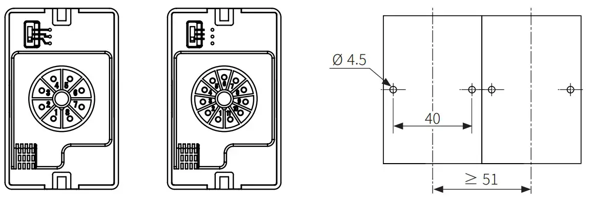
Product Components
- Product
- 8-pin socket (output: C1, V1, R1 model)
- Instruction manual
- 11-pin socket (output: C2, V2, R2, R4 model)
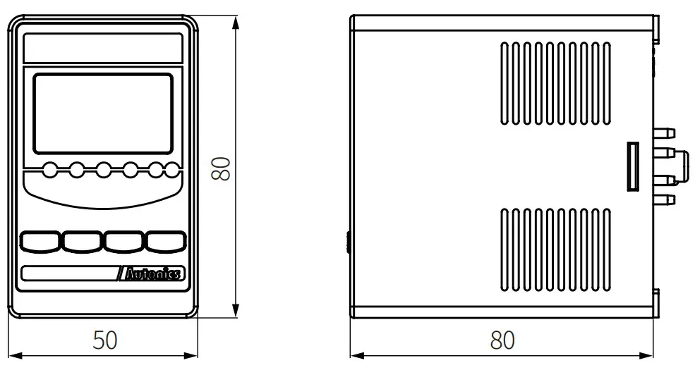
Dimensions
- Unit: mm, For the detailed drawings, follow the Autonics website. 80

- 8-pin socket
- 11-pin socket
- Panel cut-out

Input Type Selection Switch
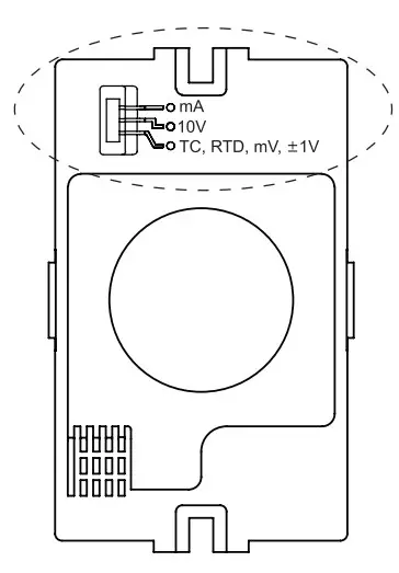
- Select the input type of the universal input model.
The pulse input model does not have this input type selection switch. - After selecting the input type with the switch, set the same input specification in the input type parameter of the program mode.
| Switch | Input |
| mA (default) | 0 (4) to 20 mA |
| 10V | -1 to 10 VDCᜡ |
| TC, RTD, mV, ±1V | Thermocouple, RTD, mV, ± 1 VDC= |
Unit Descriptions
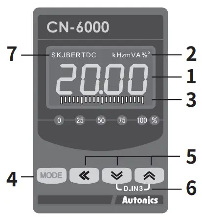
| No. | Part name | Name plate | Function |
| 1 | Display part(red, green, yellow) | – | Run mode: Displays current measured value. Set mode: Displays parameters.• Color selectable |
| 2 | Unit display part (red) | – | – |
| 3 | Output scale bar |  | [Transmission output model]Displays output as % by scale bars. |
| Alarm output indicator | [Alarm output model]Turns ON when the alarm output is on. | ||
| 4 | MODE key | [MODE] | Used to enter monitoring mode and program mode , move to parameters, save SV and return to RUN mode. |
| 5 | Setting key | [◀], [▼], [▲] | Used to change parameter SV. |
| 6 | Digital input | D.IN3 | Press the [▼] + [▲] keys for 3 sec, it operatesthe set function at digital input key parameter. |
| 7 | Input type displaypart 01) | – | [Universal input model]Turns ON when checking or changing the setting value. |
In case of thermocouple type, L, N, U, P types are not displayed. In case of RTD type, RTD is displayed.
Connections
- SOURCE: 100 – 240 VACᜠ 50 / 60 Hz 8 VA 24 VDCᜡ 3 W
Universal input (8-pin)
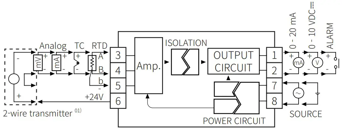
When using 2-wire transmitter, short between no.4 and 5 terminals.
Universal input (11-pin)
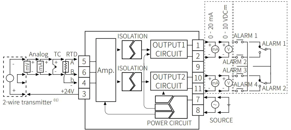
When using 2-wire transmitter, short between no.4 and 6 terminals.
Pulse input (8-pin)
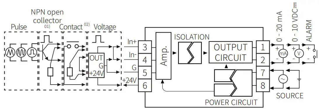
- Connect external resistance 10 kΩ (≥ 1/2W) to no.3 and 6 terminals for NPN open collector input.
- Connect external resistance 10 kΩ (≥ 1/2W) to no.3 and 5 terminals for contact input.
Pulse input (11-pin)
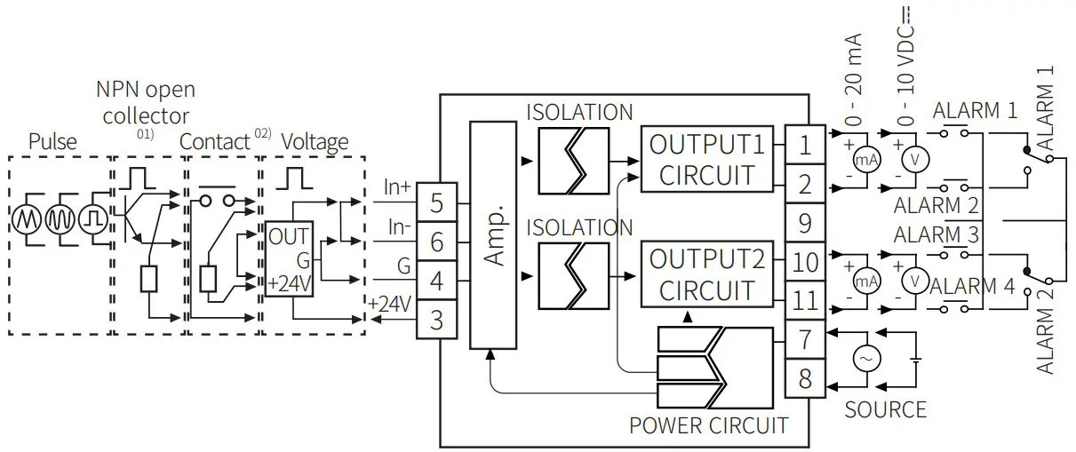
- Connect external resistance 10 kΩ (≥ 1/2W) to no.3 and 5 terminals for NPN open collector input.
- Connect external resistance 10 kΩ (≥ 1/2W) to no.4 and 5 terminals for contact input.
Specifications
| Model | CN-610□-□ | CN-640□-□ |
| Input type 01) | Universal- Temperature sensor: RTD, thermocouple- Analog: voltage, current | Pulse |
| Display method | 12-segment (selectable red, green, yellow) LCD (character size: 6.4 ×11.0 mm),Graphic bar and input type / unit display part (red) LCD (character size: 1.4 × 2.75 mm) | |
| Display accuracy 02) | Dependent on the ambient temperature | |
| 25 ± 5°C | ± 0.2 % F.S. ± 1 digit | |
| -10 to 20°C, 30 to 50°C | ± 0.3 % F.S. ± 1 digit | |
| Display cycle 03) | – | Same with pulse input cycle |
| Sampling cycle | Temperature sensor input: 250 ms Analog input: 100 ms | – |
| Unit weight (packaged) | ≈ 160 g (≈ 301 g) | ≈ 200 g (≈ 340 g) |
| Approval | ||
- For details, refer to the input type and range.
- Thermocouple, below -100 ℃: ± 0.4 % F.S. ± 1 digit
Thermocouple T, U: min. ± 2.0 ℃ - When pulse input cycle is over 10 sec, it is updated by every 10 sec
| Output | Transmission (DC 0 – 20 mA) | Transmission(0 – 10 VDCᜡ) | Alarm |
| Load resistance | ≤ 600Ω | ≥ 10 kΩ | – |
| Accuracy | ± 0.3 F.S. | – | |
| Resolution | 8,000 | – | |
| Contact capacity | – | 250 VACᜠ | |
| Contact composition | – | 5 A, 1a: 1 /3 A, 1c: 2 /5 A, 1a: 4 model | |
| Power supply | 100 – 240 VACᜠ ± 10 % 50 / 60 Hz | 24 VDCᜡ ± 10 % |
| Power consumption | ≤ 8 VA | ≤ 3 W |
| Insulation resistance | ≥ 100 MΩ (500 VDCᜡ megger) | |
| Dielectric strength | Between input terminal and power terminal: 2,000 VACᜠ 50 / 60 Hz for 1 min | |
| Vibration | 0.75 mm double amplitude at frequency of 5 to 55 Hz (for 1 minute) in each X, Y, Z direction for 2 hours | |
| Noise immunity | ± 2 kV the square wave noise (pulse width: 1 ㎲) by the noise simulator | |
| Memory retention | ≈ 10 years (non-volatile semiconductor memory type) | |
| Ambient temperature | -10 to 50 ℃, storage: -20 to 60 ℃ (no freezing or condensation) | |
| Ambient humidity | 35 to 85 %RH, storage: 35 to 85 %RH (no freezing or condensation) | |
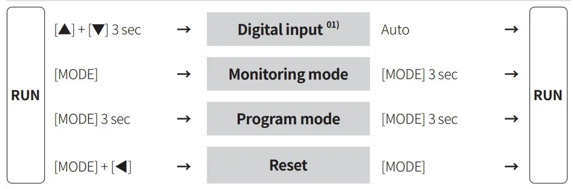
Mode Setting
P1-34, P2-30 Digital input key (HOLD: hold display value or ZERO: remote zero)
Monitoring Mode
- Some parameters are activated / deactivated depending on the model or setting of other parameters. Refer to the description of each parameter.
- If any key is not entered for 30 sec in each parameter, it returns to RUN mode.
- [MODE] key: Saves current setting value and moves to the next parameter.
- [◀] key: Changes setting digits.
- [▲], [▼] key: Changes setting values.
| Parameter | Display | Defaults | Setting range | Display condition |
| M1-1 1 CH outputvalue | —- | [Transmission output model]• Displays output value by each channel. | – | |
| M1-2 2 CH outputvalue |  | —- | ||
| M1-3 Alarm 1 value |  | [Alarm output model]Temperature sensor input: within temperature range Analog input: low-limit to high-limit scale
| P1-20 to 27,P2-19 to 26Alarm operation / option: AT1.A, AT2.A | |
| M1-4 Alarm 2 value |  | |||
| M1-5 Alarm 3 value |  | |||
| M1-6 Alarm 4 value |  | |||
| M1-7 Display max.peak value 01) | —- | Max. peak value in run mode | – | |
| M1-8 Display min.peak value 01) | —- | Min. peak value in run mode | – |
Initial max. / min. peak value is saved after 2 sec from supplying the power.
Reset: Press the [▼] + [▲] keys for at least 1 sec
Program Mode
- Some parameters are activated / deactivated depending on the model or setting of other parameters. Refer to the description of each parameter.
- If any key is not entered for 30 sec in each parameter, it returns to RUN mode.
- [MODE] key: Saves current setting value and moves to the next parameter.
- [◀] key: Changes setting digits.
- [▲], [▼] key: Changes setting values.
Universal input
| Parameter | Display | Defaults | Setting range | Display condition | ||
| P1-1 | Input type |
| – | |||
| P1-2 | Temperature unit 01) | ℃, ℉ | P1-1 Input type: Temp. sensor | |||
| P1-3 | Display unit | P1-1 Input type: Analog | ||||
| P1-4 | Low-limit input value |  | Within input type range• Low-limit input value + 20 % F.S. < High-limit input value | |||
| P1-5 | High-limit input value |  | ||||
| P1-6 | Decimal point position |  |  | |||
| P1-7 | Low-limit scale |  | -1999 to 9999 | |||
| P1-8 | High-limit scale |  | ||||
| P1-9 | Input correction | 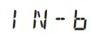 | -999 to 999 | – | ||
| P1-10 | Low-limit value of transmission output 1 | 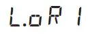 | 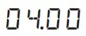 | [Transmission (DC 0 – 20 mA) output model] DC 0 – 20 mA | – | |
 | [Transmission (0 – 10 VDCᜡ) output model] 0 – 10 VDCᜡ | |||||
| P1-11 | High-limit value of transmission output 1 | 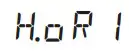 |  | [Transmission (DC 0 – 20 mA) output model] DC 0 – 20 mA | – | |
 | [Transmission (0 – 10 VDCᜡ) output model] 0 – 10 VDCᜡ | |||||
| P1-12 | Low-limit value of transmission output 2 | 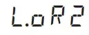 |  | [Transmission (DC 0 – 20 mA) output model] DC 0 – 20 mA | – | |
 | [Transmission (0 – 10 VDCᜡ) output model] 0 – 10 VDCᜡ | |||||
| P1-13 | High-limit value of transmission output 2 | 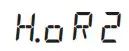 |  | [Transmission (DC 0 – 20 mA) output model] DC 0 – 20 mA | – | |
 | [Transmission (0 – 10 VDCᜡ) output model] 0 – 10 VDCᜡ | |||||
| P1-14 | Bar display CH |  | [Transmission output model]OUT1, OUT2 | P1-37 User level: HIGH | ||
| P1-15 | Low-limit scale value of transmission output 1 |  | [Transmission output model]Temperature sensor input: within temperature range Analog input: low-limit to high-limit scale | – | ||
| P1-16 | High-limit scale value of transmission output 1 |  | ||||
| P1-17 | Low-limit scale value of transmission output 2 | | ||||
| P1-18 | High-limit scale value of transmission output 2 | | ||||
| P1-19 | Input and transmission output extension 02) | [Transmission output model]5P: output DC 3.2 – 20.8 mA, 0 – 10.5 VDCᜡout of 5 % of analog input range10P: output DC 2.4 – 21.6 mA, 0 – 11 VDCᜡout of 10 % of analog input range 0P: output DC 4 – 20 mA, 0 – 10 VDCᜡ inthe analog input range | P1-1 Inputtype: Analog &P1-37User level: HIGH | |||
| P1-20 | Alarm 1operation | 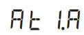 □□□.■ | [Alarm output model] □□□ AT1: Absolute high limit alarm, AT2: Absolute low limit alarm, SBA: sensor break alarm,AT0: no alarm output | – | ||
| P1-21 | Alarm 1 option | [Alarm output model] ■A: standard alarm, B: alarm latch, C: standby sequence,D: alarm latch and standby sequence• Enter alarm option setting mode: Operate in ‘Alarm 1 operation’ mode select AT1 or AT2 and input [◀] key | – | |||
| P1-22 | Alarm 2operation | 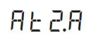 □□□.■ | [Alarm output model]Same as ‘P1-20 / 21 Alarm 1 operation/ option’• Depending on the number of alarm outputs, whether to display alarm 3 / 4 is different. | – | ||
| P1-23 | Alarm 2 option | |||||
| P1-24 | Alarm 3operation | 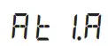 □□□.■ | ||||
| P1-25 | Alarm 3 option | |||||
| P1-26 | Alarm 4operation |  □□□.■ | ||||
| P1-27 | Alarm 4 option | |||||
| P1-28 | Alarm output hysteresis | [Alarm output model]001 to 999 | P1-20 to 27Alarm operation/ option:AT1.A, AT2.A | |||
| P1-29 Input specialfunction | LIN: output the input value,ROOT: output the square root of the input value,SQAR: output the square of the input value,TUF: Two Unit Function 01) | P1-1 Input type: Analog | ||||
| P1-30 Atmosphericpressure | Low-limit to high-limit input value | P1-1 Input type: Analog &P1-29 Input special function:TUF | ||||
| P1-31 Spancorrection | 0.900 to 1.100 | P1-1 Inputtype: Analog &P1-37User level: HIGH | ||||
| Normal P1-32 averagedigital filter | 01 (OFF) to 16 | P1-37User level: HIGH | ||||
| Moving P1-33 averagedigital filter |  | |||||
| P1-34 Digital input key |  | HOLD: hold display value,ZERO: remote zero, AL.RE: alarm reset 02)• Press the [◀] + [▲] keys for 3 sec tooperates with the set function. | – | |||
| P1-35 Display part color 03) |  | GRN: green / green,YELO: yellow / yellow, RED: red / red, R–G: red / green, G–R: green / red• Display: normal / error occur | – | |||
| SensorP1-36 disconnectionalarm output |  | ON, OFF
| P1-1 Input type: Temp. sensor | |||
| P1-37 User level | STND, HIGH | – | ||||
| P1-38 Lock | OFF: program / monitoring mode -enable to check and setting LOC1: program mode – enable to check, monitoring mode – enable to checkand setting LOC2: program mode – disable to check andsetting, monitoring mode – enable to check | – | ||||
- When changing the setting value, input type, high / low-limit scale, high / low-limit scale value of transmission output 1 / 2, and AL1 to 4 are reset.
- 0 mA, 0 VDCᜡ or less cannot be expanded. 1 VDCᜡ, 10 VDCᜡ input are available to extend only 5 %.
- Pressure of pressure sensor < atmospheric pressure: display of vacuum degree in mmHg unit
Pressure of pressure sensor > atmospheric pressure: display of positive pressure in kg/cm2 - In the alarm output model, AL.RE displayed when the setting value of P1-21, 23, 25, 27 Alarm1 ~ 4 options are alarm latch or alarm latch and standby sequence.
- The color of the display part in monitoring mode and program mode is red.
Pulse input
| Parameter | Display | Defaults | Setting range | Display condition | |
| P2-1 | Input type |
| – | ||
| P2-2 | Display unit | kHz, Hz, %, OFF | – | ||
| P2-3 | Low-limit input value | Within input type range• Low-limit input value + 20 % F.S. < High-limit input value | – | ||
| P2-4 | High-limit input value | ||||
| P2-5 | Decimal point position |  | 0.0, 0.00, 0.000, 0• Set the decimal point position of thehigh / low-limit scale. | – | |
| P2-6 | Low-limit scale |  | -1999 to 9999 | – | |
| P2-7 | High-limit scale |  | |||
| P2-8 | Input correction | -999 to 999 | – | ||
| P2-9 | Low-limit value of transmission output 1 |  | [Transmission (DC 0 – 20 mA) output model] DC 0 – 20 mA | – | |
 | [Transmission (0 – 10 VDCᜡ) output model] 0 – 10 VDCᜡ | ||||
| P2-10 | High-limit value of transmission output 1 |  | [Transmission (DC 0 – 20 mA) output model] DC 0 – 20 mA | – | |
 | [Transmission (0 – 10 VDCᜡ) output model] 0 – 10 VDCᜡ | ||||
| P2-11 | Low-limit value of transmission output 2 |  | [Transmission (DC 0 – 20 mA) output model] DC 0 – 20 mA | – | |
 | [Transmission (0 – 10 VDCᜡ) output model] 0 – 10 VDCᜡ | ||||
| P2-12 | High-limit value of transmission output 2 |  | [Transmission (DC 0 – 20 mA) output model] DC 0 – 20 mA | – | |
 | [Transmission (0 – 10 VDCᜡ) output model] 0 – 10 VDCᜡ | ||||
| P2-13 | Bar display CH |  |  | [Transmission output model]OUT1, OUT2 | P2-32 User level: HIGH |
| P2-14 | Low-limit scale value of transmission output 1 |  | [Transmission output model]Low-limit to high-limit scale | – | |
| P2-15 | High-limit scale value of transmission output 1 |  | |||
| P2-16 | Low-limit scale value of transmission output 2 |  | |||
| P2-17 | High-limit scale value of transmission output 2 |  | |||
| P2-18 | Input and transmission output extension |  | [Transmission output model]5P: output DC 3.2 – 20.8 mA, 0 – 10.5 VDCᜡout of 5 % of analog input range10P: output DC 2.4 – 21.6 mA, 0 – 11 VDCᜡout of 10 % of analog input range 0P: output DC 4 – 20 mA, 0 – 10 VDCᜡ inthe analog input range | P2-32 User level: HIGH | |
| P2-19 | Alarm 1operation | □□□.■ | [Alarm output model] □□□ AT1: Absolute high limit alarm, AT2: Absolute low limit alarm, SBA: sensor break alarm,AT0: no alarm output | – | |
| P2-20 | Alarm 1 option | [Alarm output model] ■A: standard alarm, B: alarm latch, C: standby sequence,D: alarm latch and standby sequence• Enter alarm option setting mode: Operate in ‘Alarm 1 operation’ mode select AT1 or AT2 and input [◀] key | – | ||
| P2-21 | Alarm 2operation | □□□.■ | [Alarm output model]Same as ‘P2-19 / 20 Alarm 1 operation/ option’• Depending on the number of alarm outputs, whether to display alarm 3 / 4 is different. | – | |
| P2-22 | Alarm 2 option | ||||
| P2-23 | Alarm 3operation | □□□.■ | |||
| P2-24 | Alarm 3 option | ||||
| P2-25 | Alarm 4operation | □□□.■ | |||
| P2-26 | Alarm 4 option | ||||
| 27 | Alarm output hysteresis |  | [Alarm output model]001 to 999 | P2-19 to 26Alarm operation/ option: AT1.A,AT2.A | |
| P2-28 | Spancorrection |  | 0.900 to 1.100 | P2-32 User level: HIGH | |
| P2-29 | Moving average digital filter | 01 (OFF) to 16 | |||
| P2-30 | Digital input key |  | HOLD: hold display value,ZERO: remote zero, AL.RE: alarm reset 01)• Press the [◀] + [▲] keys for 3 sec to operates with the set function. | – | |
| P2-31 | Display partcolor |  | GRN: green / green,YELO: yellow / yellow, RED: red / red, R–G: red / green, G–R: green / red• Display: normal / error occur | – | |
| P2-32 | User level |  | STND, HIGH | – | |
| P2-33 | Lock | OFF: program / monitoring mode -enable to check and settingLOC1: program mode – enable to check, monitoring mode – enable to checkand settingLOC2: program mode – disable to check andsetting, monitoring mode – enable to check | – | ||
It can be applied when the setting value of the alarm option is alarm latch or alarm latch and standby sequence.
Input Type and Using Range
Universal input
| Input type | Display | Using range ( ℃) | Using range (℉) | |
| RTD | Cu50 Ω |  | -199.9 to 200.0 | -199.9 to 392.0 |
| Cu100 Ω | -199.9 to 200.0 | -199.9 to 392.0 | ||
| JPt100 Ω | -199.9 to 600.0 | -328 to 1112 | ||
| DPt50 Ω | -199.9 to 600.0 | -328 to 1112 | ||
| DPt100 Ω | -199.9 to 850.0 | -328 to 1530 | ||
| Thermocouple | K (CA) | -200 to 1350 | -328 to 2462 | |
| -328 to 1832 | ||||
| J (IC) | -199.9 to 800.0 | -328 to 1472 | ||
| E (CR) | -199.9 to 800.0 | -328 to 1472 | ||
| T (CC) | -199.9 to 400.0 | -199.9 to 752.0 | ||
| B (PR) | 400 to 1800 | 752 to 3272 | ||
| R (PR) | 0 to 1750 | 32 to 3182 | ||
| S (PR) | 0 to 1750 | 32 to 3182 | ||
| N (NN) | -200 to 1300 | -328 to 2372 | ||
| C (W5) | 0 to 2300 | 32 to 4172 | ||
| L (IC) | -199.9 to 900.0 | -328 to 1652 | ||
| U (CC) | -199.9 to 400.0 | -199.9 to 752.0 | ||
| Platinel II | 0 to 1390 | 32 to 2534 | ||
| Analog | 0.00 – 20.00 mA | -1999 to 9999
| ||
| 4.00 – 20.00 mA | ||||
| -50.0 – 50.0 mVDCᜡ | ||||
| -199.9 – 200.0 mVDCᜡ | ||||
| -1.000 – 1.000 VDCᜡ | ||||
| -1.00 – 10.00 VDCᜡ | A _ V 2 | |||
Pulse input
- Non-contact: 0 to 50 kHz / contact: 0 to 45 kHz
Displays 0 for below 0.1 Hz - Input Low Level: 0 – 1 VDCᜡ / Input High Level: 5 – 24 VDCᜡ
- Duty ratio: 30 to 70 %
- Since the response speed is slower in the low-speed pulse, 0 Hz is displayed if no pulse is input for more than 2 sec to prevent the slow response speed at 0 Hz.
| Input type | Measuring cycle | Display | Using range | |
| Pulse | 0 to 9.999 Hz | ≤ 10 sec | -1999 to 9999
| |
| 0 to 99.99 Hz | ≤ 10 sec |  | ||
| ≤ 10 sec | ||||
| 0 to 9.999 kHz | ≤ 1 sec | |||
| 0 to 50.00 kHz | ≤ 0.1 sec | |||
Reset
- Press the [MODE] + [◀] keys in run mode, parameter INIT is displayed.
- Displays the setting value as NO by pressing the [MODE] key.
- Change the setting value as YES by pressing the [▲] or [▼] keys.
- Press the [MODE] key to reset all parameter values as default and to return to run mode.
- Reset is possible when the lock parameter of the program mode is set to OFF.
Error
| Display | Description | Troubleshooting |
 | Flashes when measurement input is lower than the using range | Error display is released automatically when it is in the measured and using range. |
 | Flashes when measurement input is higher than the using range | |
 01 02 01 02 | Flashes when the temperature sensor isdisconnected | Check the input sensor status. |
 | Flashes when setting value error | Resetting after checking thesetting conditions. |
 | Flashes when the parameter setting of the input type and the selection switch setting do not match. | Check the input type. |
- Applicable to universal input model only.
- Transmission output and alarm output according to P1-36 sensor disconnection alarm output parameter setting
| Sensor disconnection alarm output | Transmission output (DC 4 – 20 mA) | Alarm output | |
| AbsoluteHigh-limit alarm | AbsoluteLow-limit alarm | ||
| ON | 20 mA | ON | OFF |
| OFF | 4 mA | OFF | ON |
8, Bansong-ro 513Beon-gil, Haeundae-gu, Busan, Republic of Korea, 48002
www.autonics.com | +82-2-2048-1577 | [email protected]