![]() ISOSLICE-5
ISOSLICE-5
8 Reconfigurable Digital Input Isoslice Unit
User Manual
ISOSLICE-5 8 Reconfigurable Digital Input Isoslice Unit
ISOSLICE-5
This slice unit has 8 digital inputs.
The inputs can be configured to work in two different ways, depending on the position of the links inside. It is possible to have some inputs configured as volt-free contacts and the others configured as +24Vdc inputs.
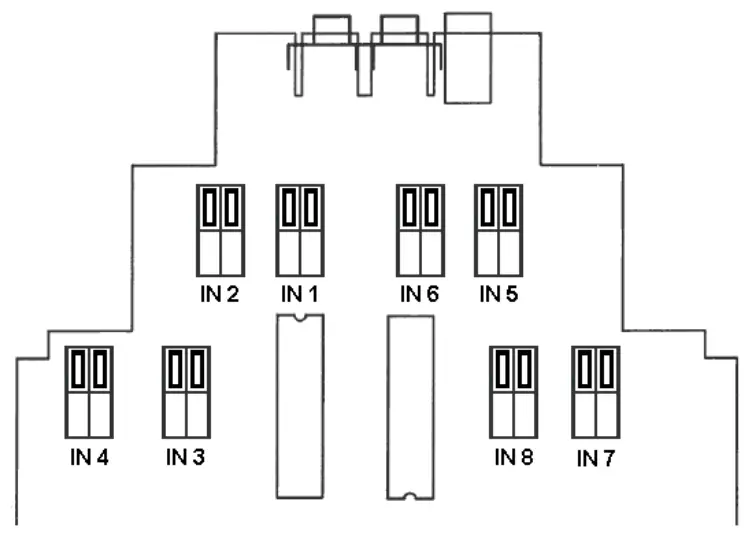
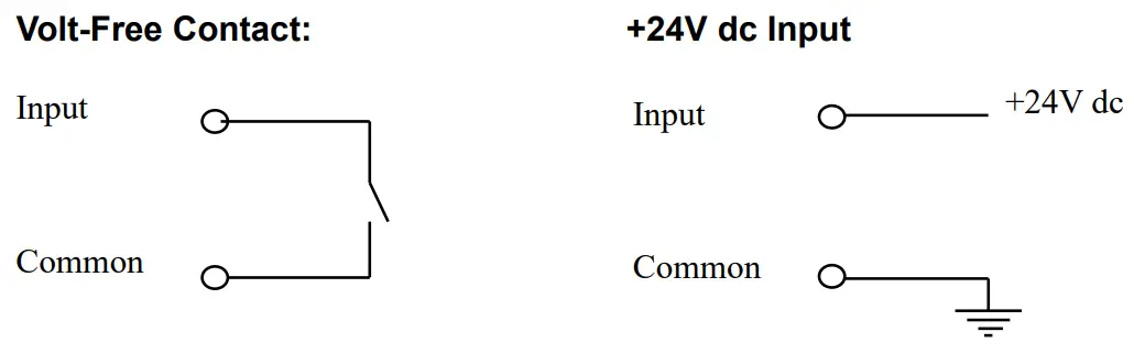
Volt Free Contact
The Input terminal must be connected to the Common terminal to switch the input “ON”.
The input links must be fitted in the higher positions like this:
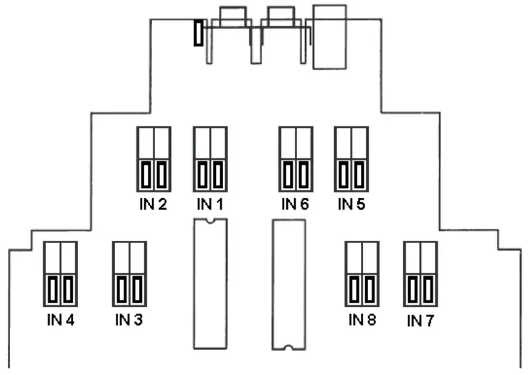
+24V dc Input
+24V dc must be connected to the Input terminal, with the corresponding Ground to the Common terminal, to switch the input “ON”.
The input links must be fitted in the lower positions like this:
It is possible to have some inputs configured as volt-free contacts and the others configured as +24Vdc inputs.
The logic can be reversed if switch 1 of S1 is on, so the inputs are“OFF” instead of “ON” when the circuits are completed as described earlier.
Links must be fitted in pairs as shown above to avoid the possibility of shorting +24V dc directly to the ground.
Channel Number
The channel number is set up using the 12-way dipswitch.
If all switches are off, the channel number is 1 (invalid):
| Address Switches | Action | 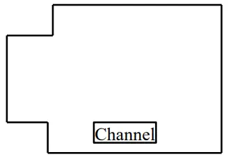 |
| 8 | add 1 | |
| 7 | add 2 | |
| 6 | add 4 | |
| 5 | add 8 | |
| 4 | add 16 | |
| 3 | add 32 | |
| 2 | add 64 |
| Switches 1 = On, 0 = Off | |||||||
| Channel | 2 | 3 | 4 | 5 | 6 | 7 | 8 |
| 1 | 0 | 0 | 0 | 0 | 0 | 0 | 0 |
| 2 | 0 | 0 | 0 | 0 | 0 | 0 | 1 |
| 3 | 0 | 0 | 0 | 0 | 0 | 1 | 0 |
| 4 | 0 | 0 | 0 | 0 | 0 | 1 | 1 |
| 5 | 0 | 0 | 0 | 0 | 1 | 0 | 0 |
| 6 | 0 | 0 | 0 | 0 | 1 | 0 | 1 |
| 7 | 0 | 0 | 0 | 0 | 1 | 1 | 0 |
| 8 | 0 | 0 | 0 | 0 | 1 | 1 | 1 |
| 9 | 0 | 0 | 0 | 1 | 0 | 0 | 0 |
| 10 | 0 | 0 | 0 | 1 | 0 | 0 | 1 |
| 11 | 0 | 0 | 0 | 1 | 0 | 1 | 0 |
| 12 | 0 | 0 | 0 | 1 | 0 | 1 | 1 |
| 13 | 0 | 0 | 0 | 1 | 1 | 0 | 0 |
| 14 | 0 | 0 | 0 | 1 | 1 | 0 | 1 |
| 15 | 0 | 0 | 0 | 1 | 1 | 1 | 0 |
| 16 | 0 | 0 | 0 | 1 | 1 | 1 | 1 |
Switch 1 can be used to reverse the on/off logic of all 8 inputs.
Connections
The digital inputs are wired as shown:
7. Digital Input 7
8. Digital Input 8
12. Common
5. Digital Input 5
6. Digital Input 6
11. Common
1. Digital Input 1
2. Digital Input 2
9. Common
3. Digital Input 3
4. Digital Input 4
10. Common
Whilst every effort has been taken to ensure the accuracy of this document, we accept no responsibility for damage, injury, loss, or expense resulting from errors or omissions, and reserve the right of amendment without notice.
This document may not be reproduced in any way without the prior written permission of the company
AUG 2022
Sensata Technologies
220808


