Sensata ISOSLICE-6 4 Output Relay Isoslice Unit Owner’s Manual
Whilst every effort has been taken to ensure the accuracy of this document, we accept no responsibility for damage, injury, loss, or expense resulting from errors or omissions, and reserve the right of amendment without notice.
This document may not be reproduced in any way without the prior written permission of the company
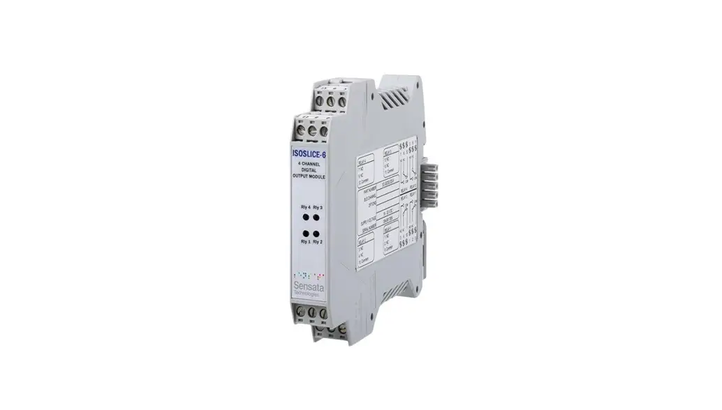
Isoslice-6
This isoslice unit has 4 relay outputs.
Channel Number
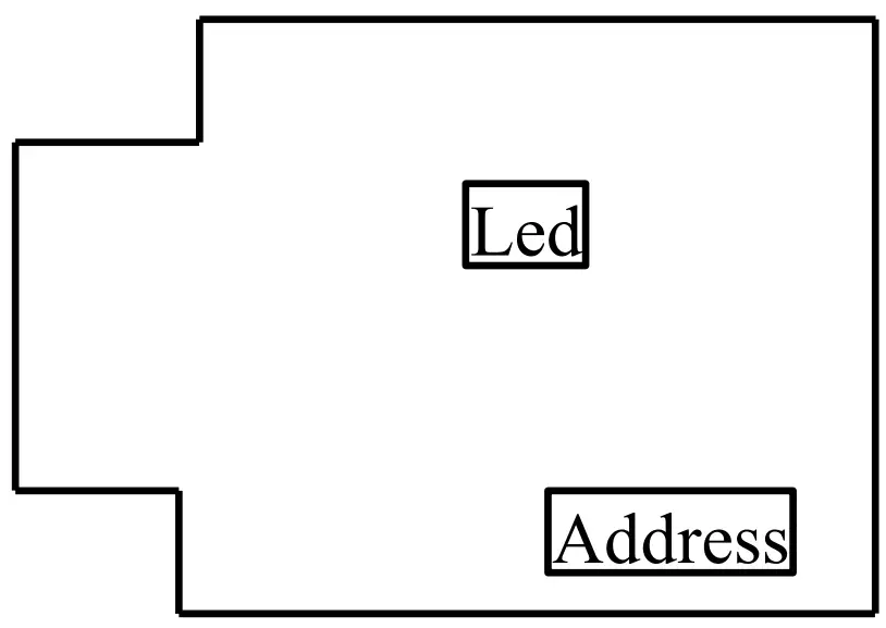
The channel number is set up using the 8-way dipswitch.
| Address Switch | Action |
| 8 | add 1 |
| 7 | add 2 |
| 6 | add 4 |
| 5 | add 8 |
| 4 | add 16 |
| 3 | add 32 |
| 2 | add 64 |
| 1 | is not used |
Switches
1 = On, 0 = Off
| Channel | 2 | 3 | 4 | 5 | 6 | 7 | 8 |
| 1 | 0 | 0 | 0 | 0 | 0 | 0 | 0 |
| 2 | 0 | 0 | 0 | 0 | 0 | 0 | 1 |
| 3 | 0 | 0 | 0 | 0 | 0 | 1 | 0 |
| 4 | 0 | 0 | 0 | 0 | 0 | 1 | 1 |
| 5 | 0 | 0 | 0 | 0 | 1 | 0 | 0 |
| 6 | 0 | 0 | 0 | 0 | 1 | 0 | 1 |
| 7 | 0 | 0 | 0 | 0 | 1 | 1 | 0 |
| 8 | 0 | 0 | 0 | 0 | 1 | 1 | 1 |
| 9 | 0 | 0 | 0 | 1 | 0 | 0 | 0 |
| 10 | 0 | 0 | 0 | 1 | 0 | 0 | 1 |
| 11 | 0 | 0 | 0 | 1 | 0 | 1 | 0 |
| 12 | 0 | 0 | 0 | 1 | 0 | 1 | 1 |
| 13 | 0 | 0 | 0 | 1 | 1 | 0 | 0 |
| 14 | 0 | 0 | 0 | 1 | 1 | 0 | 1 |
| 15 | 0 | 0 | 0 | 1 | 1 | 1 | 0 |
| 16 | 0 | 0 | 0 | 1 | 1 | 1 | 1 |
Led Control
There are 4 LEDs to indicate the state of the individual relays. The action of these LEDs is controlled by the 4-way dip switch. By default, the LED will be on when the relay is energized, when the corresponding dipswitch (switch 1 is relay 1, etc.) is in the off position.
Individual LED actions can be reversed by switching the corresponding dipswitch on.
Connections
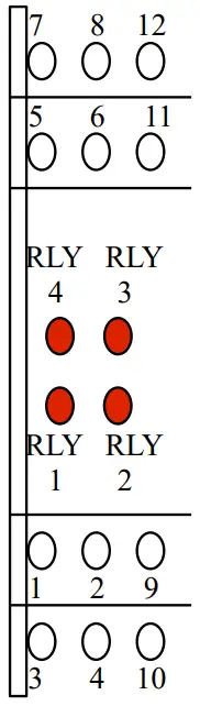
- 7. Relay 4 NO
- 8. Relay 4 NC
- 12. Relay 4 COM
- 5. Relay 3 NO
- 6. Relay 3 NC
- 11. Relay 3 COM
- 1. Relay 1 NO
- 2. Relay 1 NC
- 9. Relay 1 COM
- 3. Relay 2 NO
- 4. Relay 2 NC
- 10. Relay 2 COM