![]()
![]()
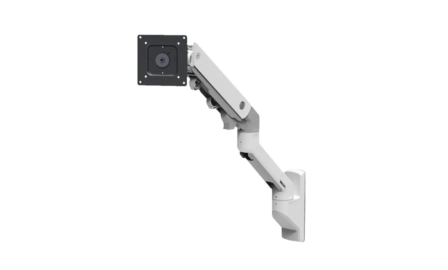
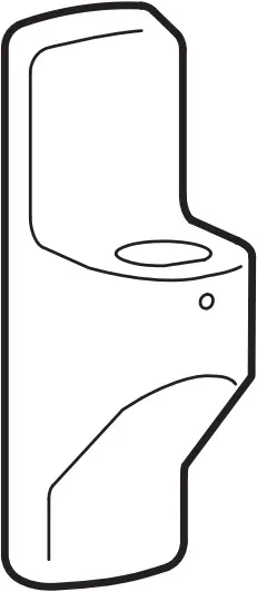
HX
Wall Monitor Arm
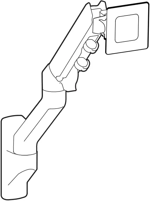 Includes Constant Force™ Technology
User Guide
 | A | B | C | D | E |
1 | 1x
| 1x
| 1x
| 1x
| |
2 | 1x
| 1x
M4 x 8mm | 2x
M6 x 14mm | 4x
M4 x 10mm | 4x
M4 x 10mm |
3 | 4x
M4x12mm | 4x
M5x12mm | 4x
M6x12mm | 4x
M5x20mm | 2x
11.5 x 6.5 x 1 |
4 | 4x
M5 – M8 Reducer | 4x
| 4x M5 x 7mm | 1x
| 1x
|
5 | 4x
10-24 x 5/8” | 2x
M8 | 2x
M8 x 80mm | ||

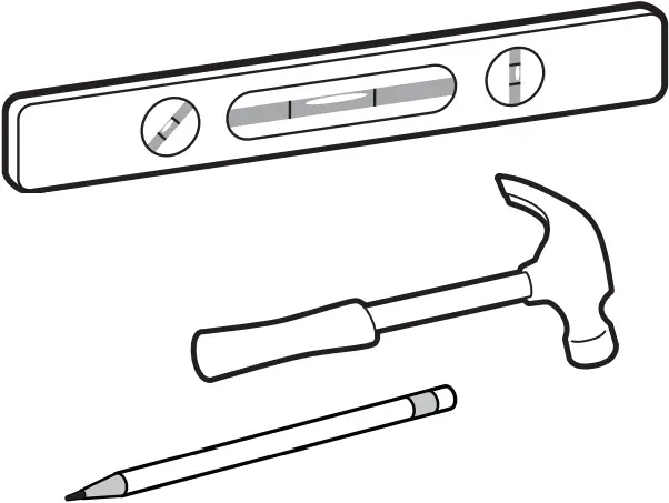
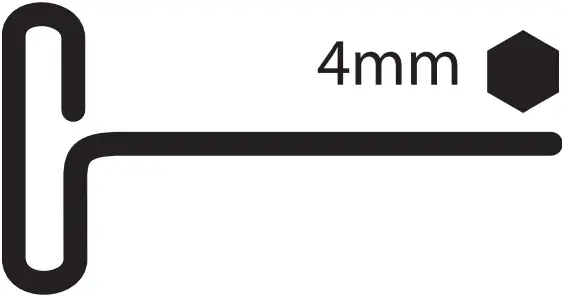
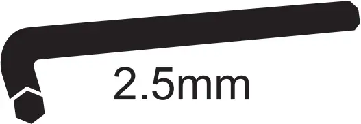
Tools Needed

CONCRETE ![]() Ø 3/8″ (10mm)
Ø 3/8″ (10mm)
![]() 13mm
13mm
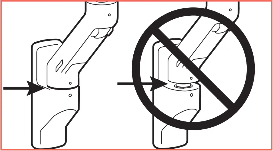
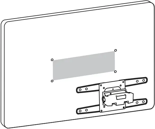
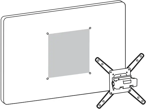
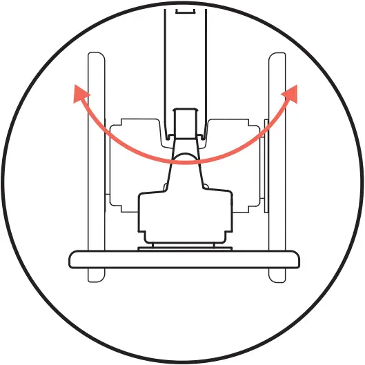
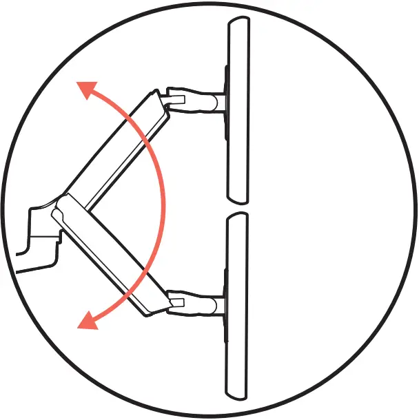
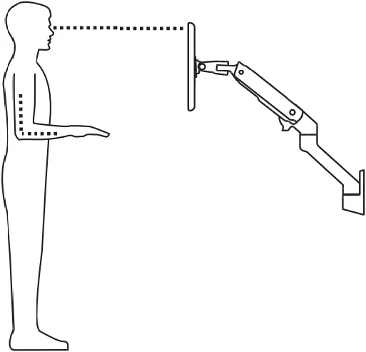
(1) Determine mounting location:
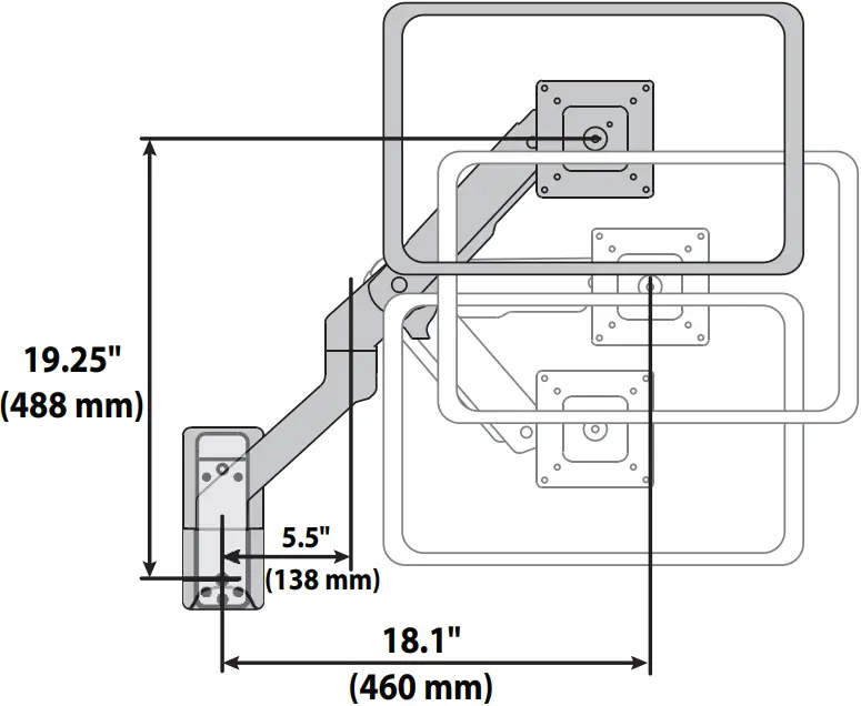
Front view with arm pushed back against the wall.
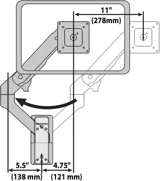
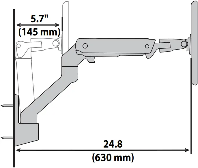
Top view showing range of motion when pulled out from the wall.
NOTE: Determine if arm will typically collapse to the left or right before installation.
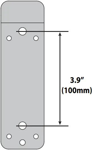
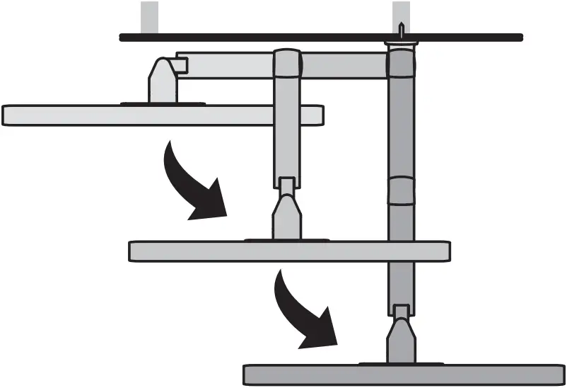
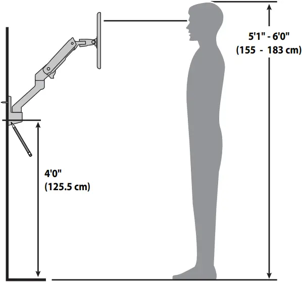
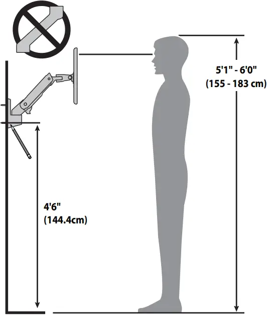
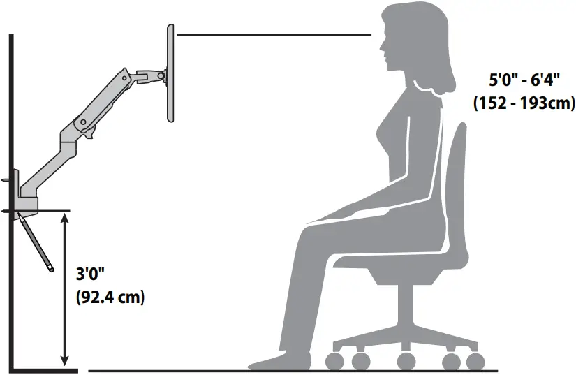
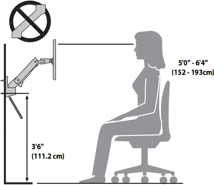
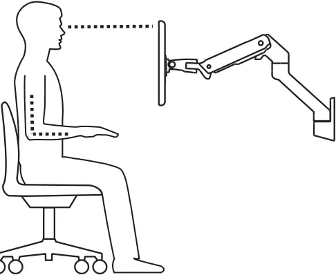
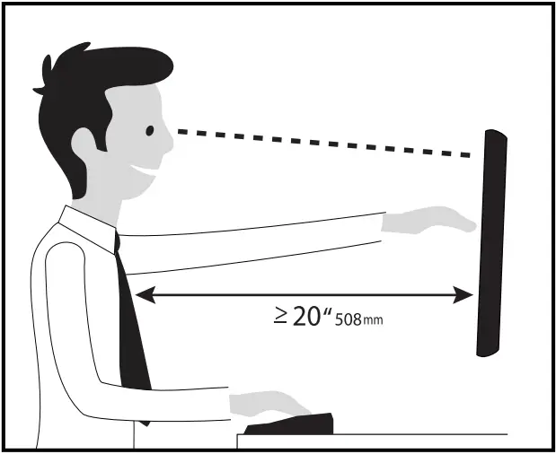
(2) Mounting Height for Ergonomic Workstation
This mounting height is a recommendation for an ergonomic workstation that accommodates user heights of 5’1-6’0″ (154.9-182.8cm) when set up for standing and user heights of 5’0-6’4″ (152-193cm) when set up for sitting.
If user heights are different than this, you should change mounting height to accommodate user heights. (Change mounting height one inch for every one inch difference in user heights).
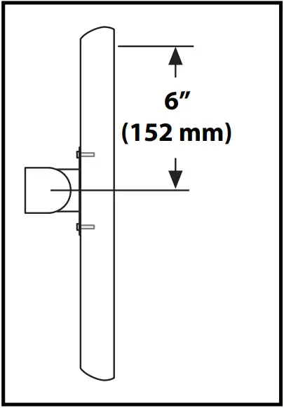
Mounting height assumes there is a 6″ (152 mm) distance between the center of your monitor mounting holes and the top of the screen. If your distance is smaller, you should increase mounting height accordingly, if your distance is larger, you should decrease your mounting height accordingly.
Mounting Height for Ergonomic Workstation
(3) 
1 2
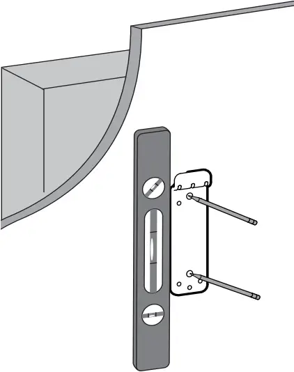
(4) ERGOTRON PRODUCT CONCRETE

![]()

Warning: Ensure that the wall structure is capable of supporting four times the total weight of mounted equipment. Mounting to wall surfaces that do not meet this criteria may result in an unstable, unsafe condition which could lead to personal injury and/or property damage. Consult a construction professional if you have any doubt about what this means in regard to your particular application.
CAUTION: Make sure the wall mount bracket is level, flush and snug to the wall surface. DO NOT OVERTIGHTEN THE BOLTS.
ERGOTRON PRODUCT
1 4x ![]() 10-24 x 5/8″ 2
10-24 x 5/8″ 2
![]()
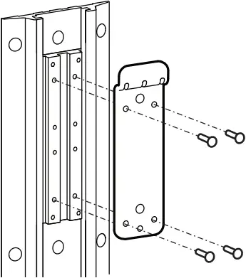
3 4 1x ![]()
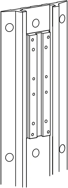
NOTE: Well Track and Brackets sold separately.
NOTE: Fasteners may unwind due to vibration caused by movement of mounting solution over time. Inspect mounting solution for loose fasteners on a routine basis. If desired, apply a light duty thread locking adhesive to fasteners before installation to prevent back-out.

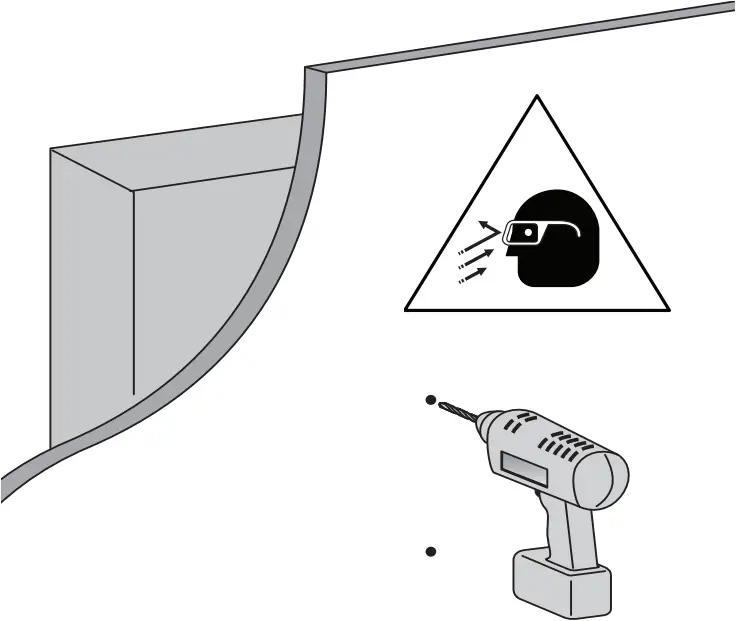
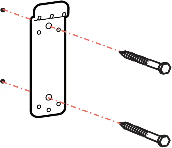
 CONCRETE
![]() Ø 3/8″ (10mm)
Ø 3/8″ (10mm) ![]()
![]() 13mm 2x
13mm 2x 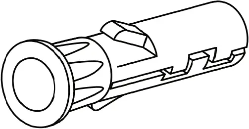 M8
M8
1x ![]() 2x
2x ![]() M8 x 80mm
M8 x 80mm
WARNING: Mounting holes must be at least 3-1/8″ (80mm) deep and must be located within solid concrete, not mortar or covering material. If you drill into an area of concrete that is not solid, reposition mounting holes until both anchors can be fully inserted into solid concrete!
WARNING: Anchors that are not fully set in solid concrete will not support the applied load resulting in an unstable, unsafe condition which could lead to personal injury and/or property damage. Consult a construction professional if you have any doubt about what this means in regard to your particular situation.
1 2 ![]() Ø 3/8″ (10mm)
Ø 3/8″ (10mm)
3 2x ![]() M8 4 2x
M8 4 2x ![]() M8 x 80mm
M8 x 80mm ![]() 13mm
13mm
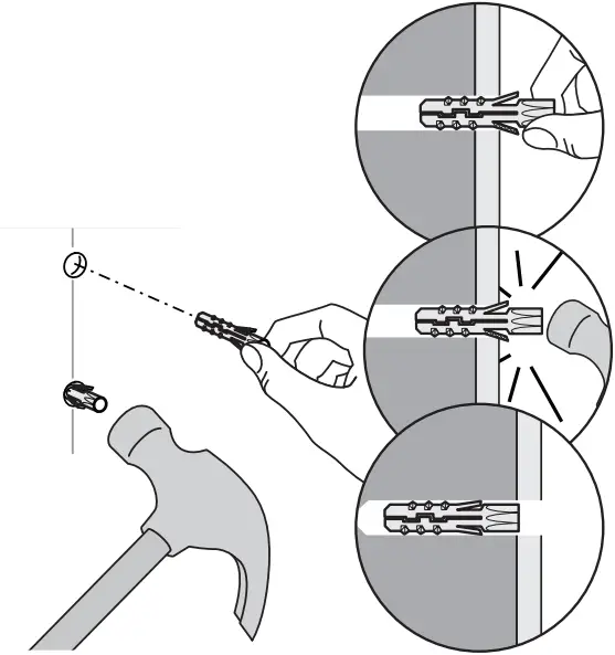
5 6 ![]() 7 1x
7 1x ![]()

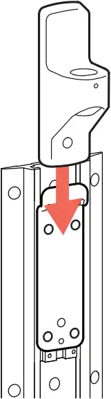
(5) 
1 2 3
4 5 6
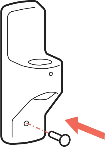
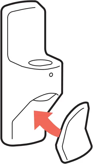
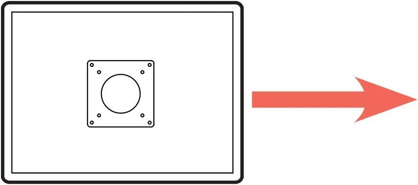
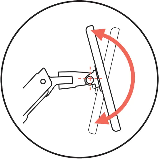
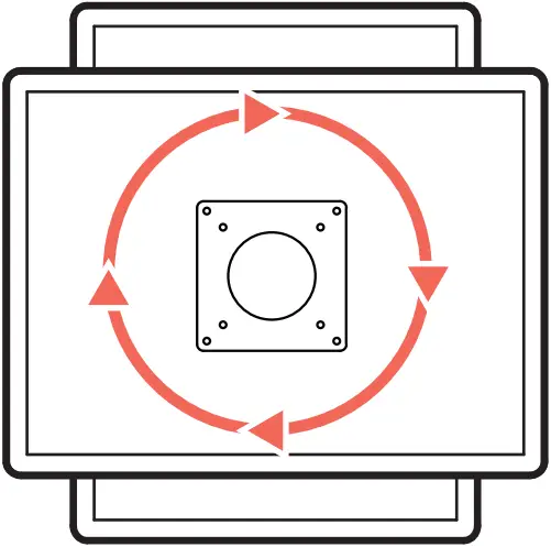
(6) Rotate – Portrait/Landscape
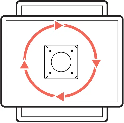
For 0° rotation, add screw.
 1x
1x ![]()
0° M4 x 8mm
(7)

![]() or
or ![]()

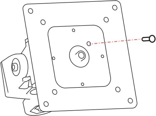
Use adapters
4x
![]()
4x ![]()
M5 x 7mm

4x ![]()
![]()
![]() 4x
4x ![]()
M4 x 10mm M4 x 10mm
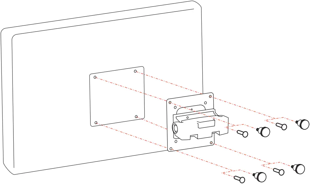
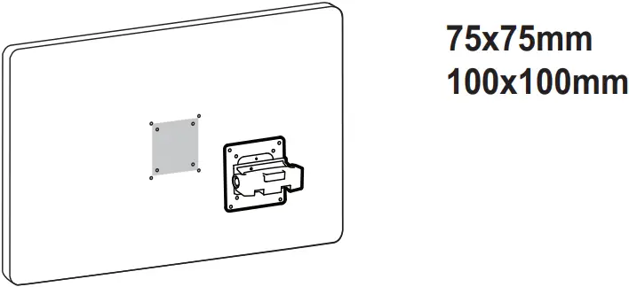
Skip to page 15 to continue installation 
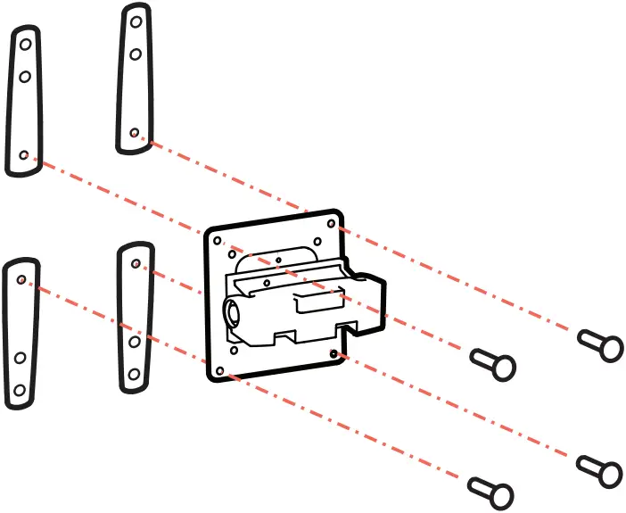
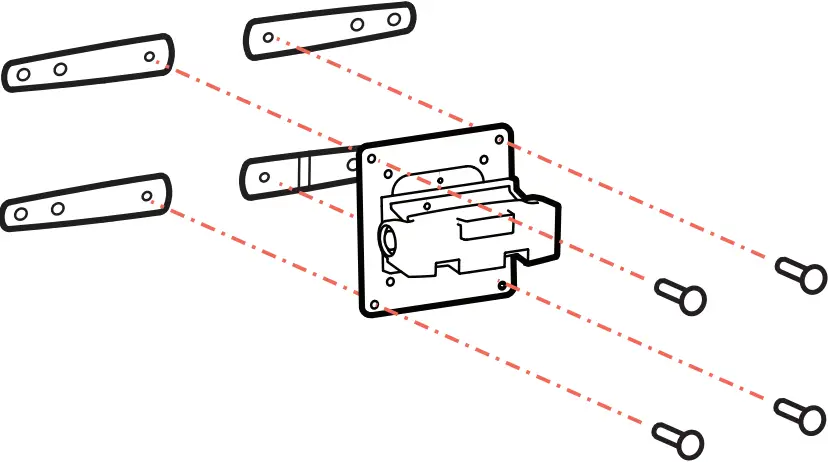
100x200mm 200x100mm
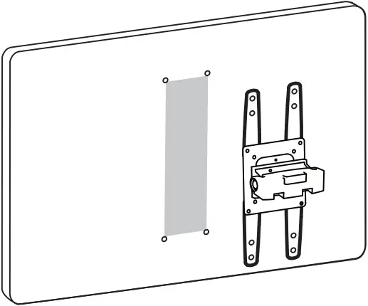
200x200mm
1 4x ![]() 4x
4x ![]() M5 x 7mm
M5 x 7mm ![]()
or or

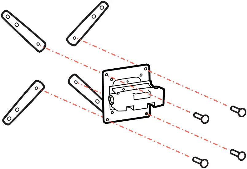
2 Use the size of screw that fits your monitor.
4x ![]() M4x12mm
M4x12mm ![]() 4x
4x ![]() M5x12mm
M5x12mm ![]() 4x
4x ![]() M6x12mm
M6x12mm ![]()
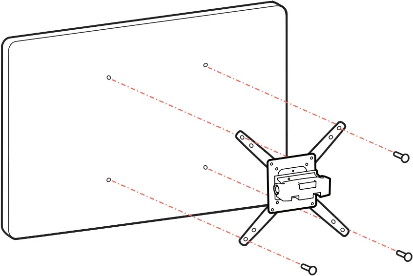

NOTE: To reduce or holes for use with or screws, or if you have a model with Samsung holder rings, follow the M8M5 KIT instructions on the next page.
M8M5 KIT Instructions
NOTE: follow this step only if your TV/monitor has M8 holes which need to be reduced to or or for Samsung models using the holder ring.
4x ![]() M8-M5 Reducer 4x
M8-M5 Reducer 4x ![]() M5x20mm
M5x20mm ![]()
![]()
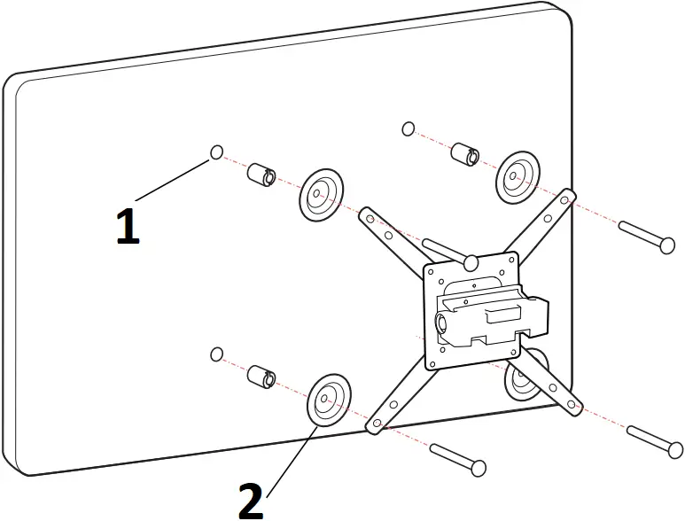
- TV/Monitor Mounting
M8 size hole - Holder Ring
(Not included *Samsung Only)
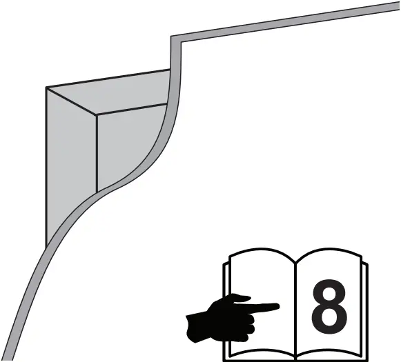
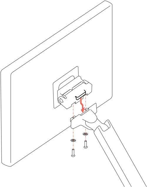
(8)
2x ![]() M6 x 14mm 2x
M6 x 14mm 2x ![]() 11.5 x 6.5 x 1
11.5 x 6.5 x 1 ![]()
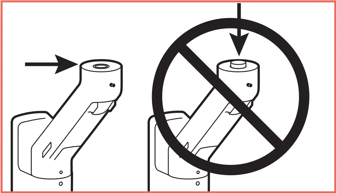
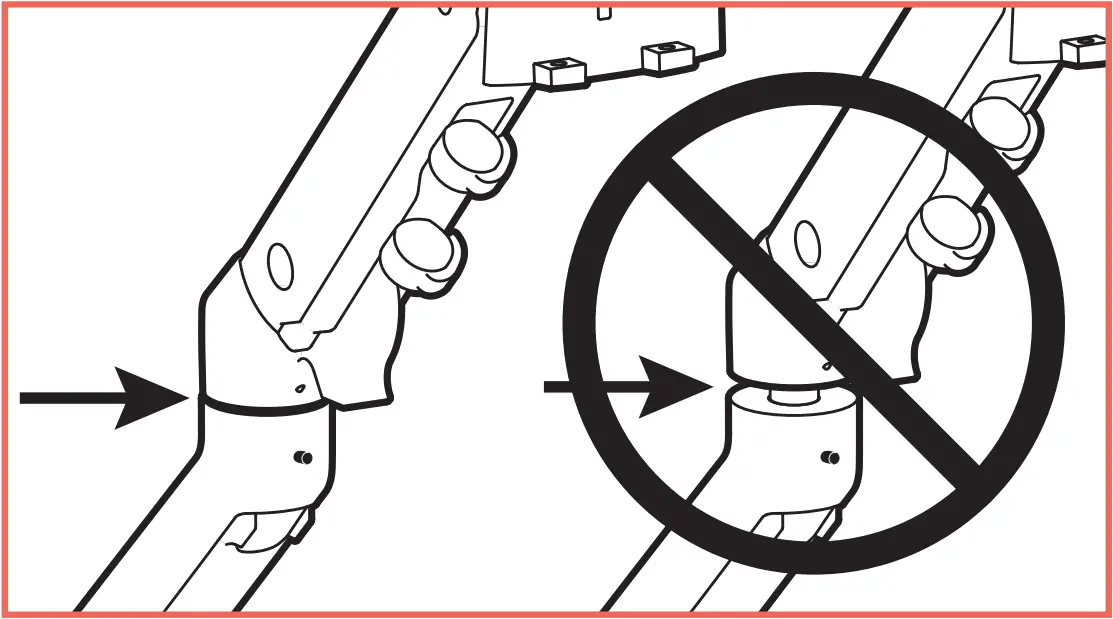
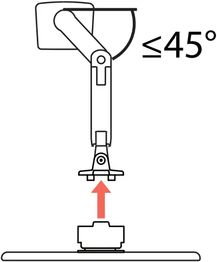 NOTE: Arm exstension should be at a 45° angle or less when attaching monitor.
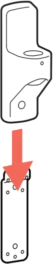
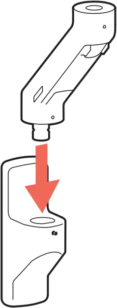
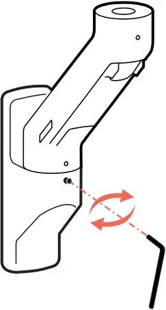
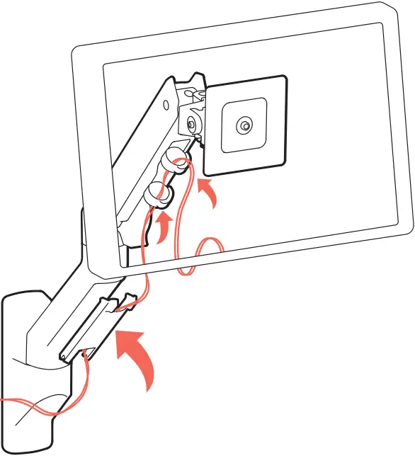
(9)
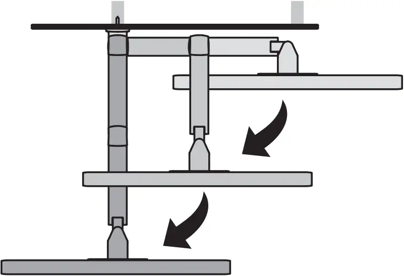
(10) Adjustment Step
Important! You will need to adjust this product after installation is complete. Make sure all your equipment is properly installed on the product before attempting adjustments. This product should move smoothly and easily through the full range of motion and stay where you set it. If movements are too easy or difficult or if product does not stay in desired positions, follow the adjustment instructions to create smooth and easy movements. Depending on your product and the adjustment, it may take many turns to notice a difference. Any time equipment is added or removed from this product, resulting in a change in the weight of the mounted bad, you should repeat these adjustment steps to ensure safe and optimum operation.
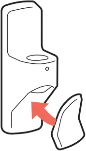
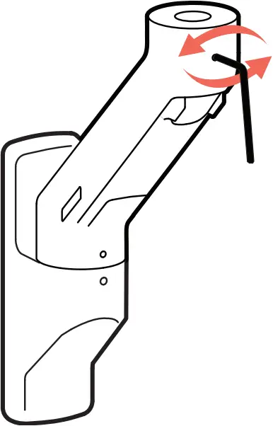
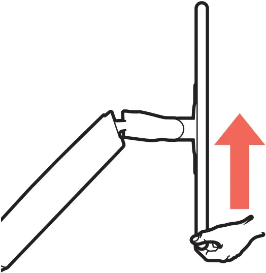
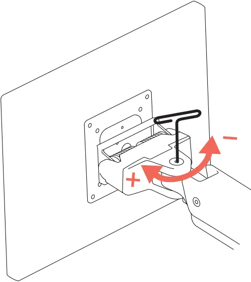
(11) Adjustment Step
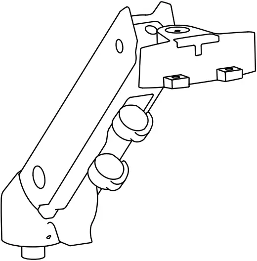
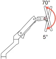
 Tilt – Forward and Backward
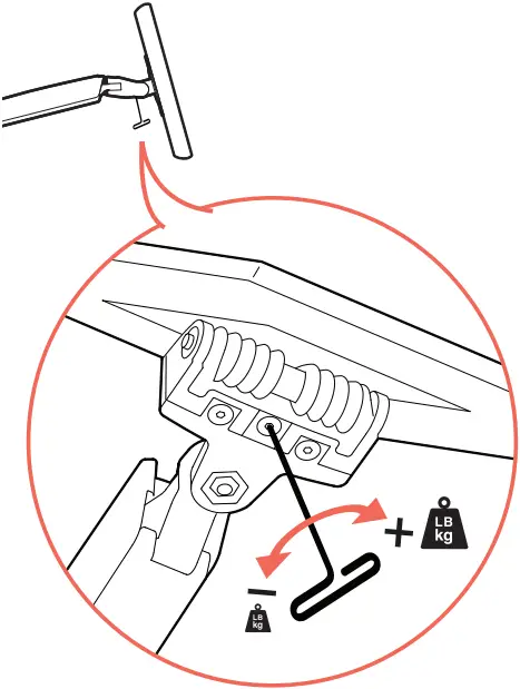
CAUTION: DO NOT remove screw. Removing screw may cause damage to equipment.
| |
 Increase Lift Strength | Decrease Lift Strength |
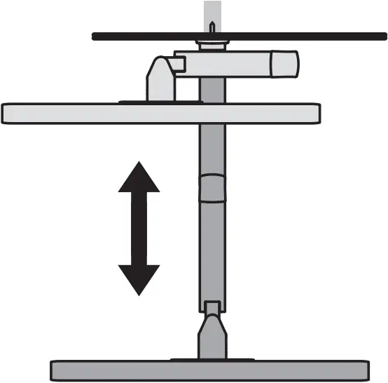
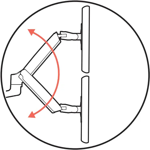
(12) Adjustment Step
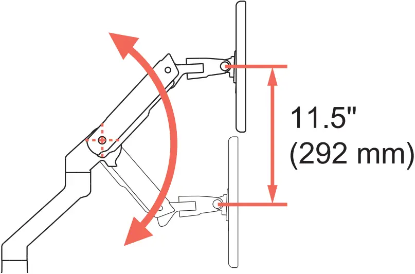
 Lift – Up and down
1
2
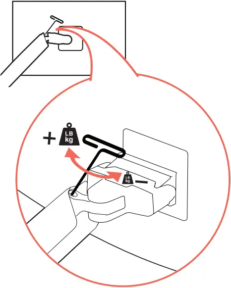
| |
Increase Lift Strength | Decrease Lift Strength |
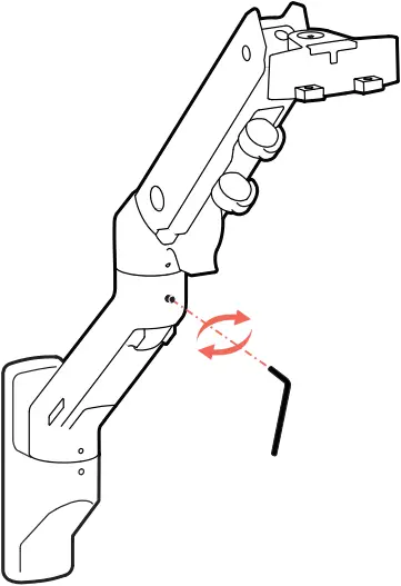
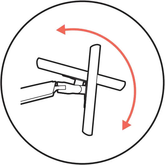
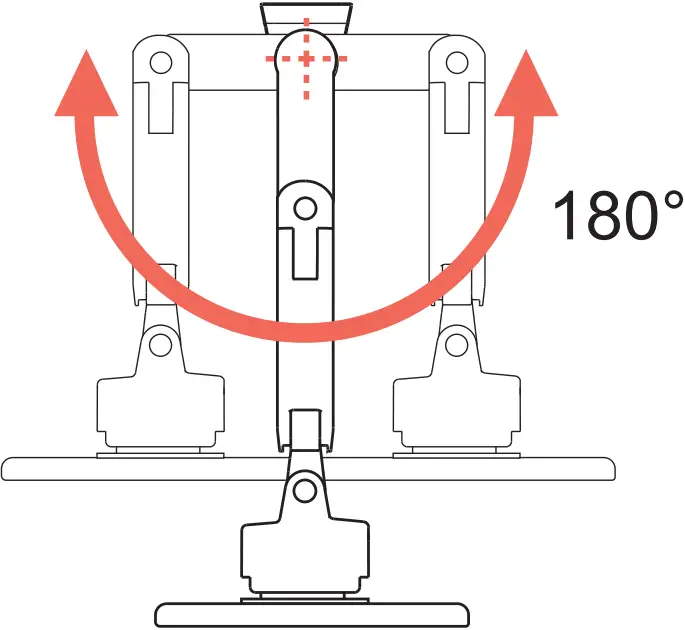
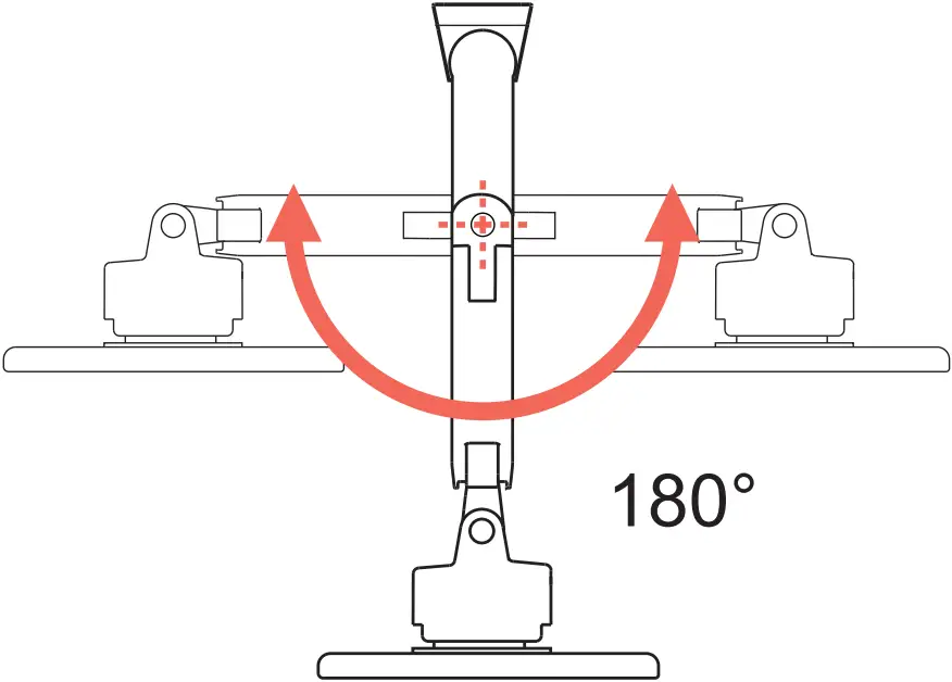
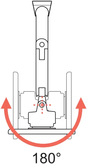
(13) Adjustment Step
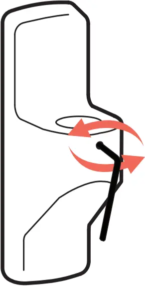
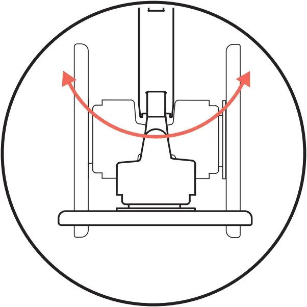 Monitor Pan – Left and Right
| |
Increase Friction | Decrease Friction |
Safety
Warning: Ensure that the wall structure is capable of supporting four times the total weight of mounted equipment. Mounting to wall surfaces that do not meet this criteria may result in an unstable, unsafe condition which could lead to personal injury and/or property damage. Consult a construction professional if you have any doubt about what this means in regard to your particular application.
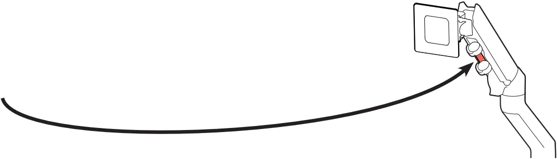
Caution: Leave enough slack in cable to allow full range of motion.
To avoid the potential to pinch cables it is important to follow the cable routing instructions in this manual. Failure to follow these instructions may result in equipment damage or personal injury.
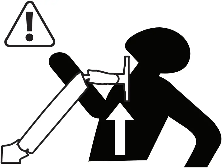
| |
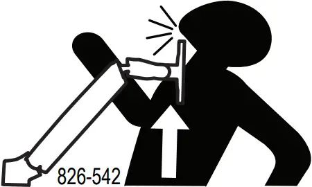 Move Arm to highest position before removing equipment or serious personal injury and/or equipment damage may occur Move Arm to highest position before removing equipment or serious personal injury and/or equipment damage may occur |
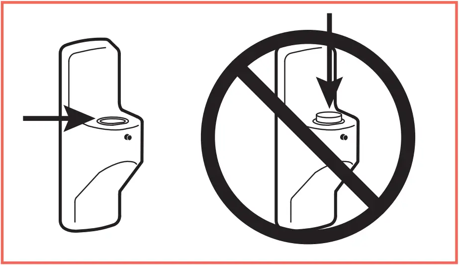
WARNING! Stored Energy Hazard: The arm mechanism is under tension and will move up rapidly, on its own, as soon as attached equipment is removed. For this mason, DO NOT remove equipment unless the arm has been moved to the highest position! Failure to follow this instruction may result in serious personal injury and/or equipment damage!
Weight Capacity:
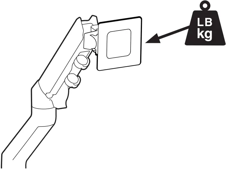 20 – 42 lbs. (9.1-19 kg)
CAUTION: DO NOT EXCEED MAXIMUM LISTED WEIGHT CAPACITY. SERIOUS INJURY OR PROPERTY DAMAGE MAY OCCUR!
For the latest User Installation Guide please visit: www.ergotron.com
For Warranty visit: www.ergotron.com/warranty
For Service visit: www.ergotron.com
For local customer care phone numbers visit. http://contact.ergotron.com
Learn more about ergonomic computer use at:
www.ergotron.com/ergonomics
NOTE: When contacting customer service, reference the serial number.
![]()
www.ergotron.com | USA: 1-800-888-8458 | Europe 31 (0)33-45 45 600 | China: 400-120-3051 | Japan: [email protected]
© 2016 Ergotron, Inc. All rights reserved.
While Ergotron,Inc. makes every effort to provide accurate and complete information on the installation and use of its products, it will not be held liable for any editorial errors or omissions (including those made in the process of translation from English to another language), or for incidental, special or consequential damages of any nature resulting from furnishing this instruction and performance of equipment in connection with this instruction, Ergotron, Inc. reserves the right to make changes in the product design and/or product documentation without notification to its users. For the most current product information, or to know if this document is available in languages other than those herein, please contact Ergotron. No part of this publication may be reproduced, stored in a retrieval system,or transmitted in any form or by any means, electronic, mechanical, photocopying, recording or otherwise without the prior written consent of Ergotron, Inc.,1181 Trapp Road, Eagan, Minnesota, 55121, USA Patents Pending and Patented U.S.& Foreign. Ergotron is a registered trademark of Ergotron, Inc.
888-45-347-G-02 rev. M • 09/21


