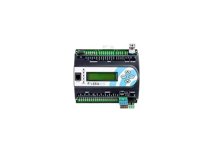
VERASYS VEC100 Generic RTU Heat Pump Controller User Guide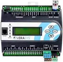
About this guide
This quick start guide provides the basic information you need to configure and install the Verasys® Equipment Controller (VEC), LC-VEC100-0, using the Verasys generic rooftop unit (RTU) heat pump controller application. The application controls a third-party changeover bypass (COBP) system or a third-party variable air volume (VAV) unit.
For further information, refer to the Verasys Equipment Controller (VEC) Installation Guide (24-10143-1272) and the VEC100 Generic RTU Heat Pump Controller Application Note (12013452).
| Options available | Possible values |
| Number of Heat Pump Stages Installed | 0 to 2 |
| Supplemental Heat Installed |
|
| Economizer Installed |
|
| Air Proving Switch Setup |
|
| Runtime Equalization |
|
| Rooftop Controller Type |
|
| Cancel ASCD Timers |
|
| Demand Ventilation Feature |
|
| Reversing Valve Config |
|
| Condensate Alarm |
|
Mounting the controller
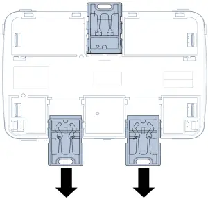
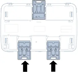
To mount the controller, complete the following steps:
- Mount a 20 cm (8 in.) section of 35 mm (1.3 in.) DIN rail horizontally.
Note: Mount the controller in the horizontal position. - On the back of the controller, extend the two mounting clips.

Figure 1: Pull down lower mounting clips - Place the controller on the DIN rail.
- Push the bottom mounting clips inward (up) to secure the controller on the DIN rail.

Figure 2: Push up lower mounting clips
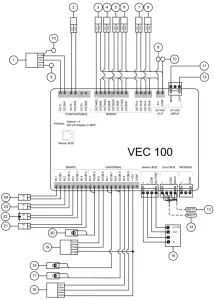
Wiring the controller
Zone bus terminal block
The zone bus terminal block is a grey, removable, 4- terminal plug that fits into a board-mounted jack. Wire the removable zone bus terminal block plugs on the controller on the top row of the stacked connector, and other field controllers in a daisy-chain configuration using 3-wire twisted, shielded cable as shown in the following figure.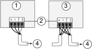
Figure 3: Zone bus terminal block wiring
| 1 | Terminating device on the zone bus |
| 2 | Zone bus terminal block plugs |
| 3 | Daisy-chained device on a zone bus segment |
| 4 | Connects to the next device on the zone bus. |
Table 2: Zone bus daisy chaining configuration
![]() Note: The zone bus shield (SHD) terminal is isolated and can be used to connect (daisy chain) the shields for zone bus wiring.
Note: The zone bus shield (SHD) terminal is isolated and can be used to connect (daisy chain) the shields for zone bus wiring.
Sensor bus terminal block
The sensor bus terminal block is a brown, removable, 4- terminal plug that fits into a board-mounted jack. Wire the removable sensor bus terminal block plugs on the lower port of the dual stacked connector to the controller, and other sensor bus devices in a daisy-chain configuration using a 4-wire twisted, shielded cable as shown in the following figure.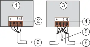
Figure 4: Sensor bus terminal block wiring
| 1 | Terminating device on the sensor bus |
| 2 | Sensor bus terminal block plug on the terminating device |
| 3 | Daisy-chained device on a sensor bus segment |
| 4 | Sensor bus terminal block plug on the daisy-chained device |
| 5 | Cable shield connection |
| 6 | Connects to the next device on the sensor bus. |
Table 3: Sensor bus daisy chaining configuration
![]() Note: The PWR terminal supplies 15 VDC. The PWR terminal can be used to connect (daisy chain) the 15 VDC power leads on the sensor bus.
Note: The PWR terminal supplies 15 VDC. The PWR terminal can be used to connect (daisy chain) the 15 VDC power leads on the sensor bus.
Supply power terminal block
The 24 VAC supply power terminal block is a gray, removable, 3-terminal plug that fits into a board-mounted jack on the top right of the controller. Wire the 24 VAC supply power wires from the transformer to the HOT and COM terminals on the terminal plug, as shown in the following figure. The middle terminal on the supply power terminal block is not used.
Disconnect supply power to controller by unplugging supply Power plug from supply power jack.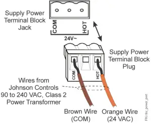
![]() Note: The supply power wire colors may be different on transformers from other manufacturers. Refer to the transformer manufacturer’s instructions and the project installation drawings for wiring details.
Note: The supply power wire colors may be different on transformers from other manufacturers. Refer to the transformer manufacturer’s instructions and the project installation drawings for wiring details.
Setting the VEC address using the local display
To set the VEC address using the local display, complete the following steps:
- To access the menu, press the ENT (Enter) button.
- Navigate to the Controller menu with the up and down arrows, and press the ENT button.
- In the Controller menu, navigate to Network and press the ENT button.
- In the Network Parameters section, navigate to Address and press the ENT button. The display shows the default address value.
- Press the ENT button. The address blinks.
- Use the up or down arrow to increase or decrease the address to the value you want. Press the ENT button. The address stops blinking and the display shows the old address.
- Press either the up or down arrow. The screen refreshes to the new address.
- Press ESC (Escape) repeatedly, until you return to the main screen. Ensure that the main screen shows that the system is operational.
Configuring sensors
To configure the installed sensors, complete the following steps:
- Navigate to the Details menu.
- Navigate to the Service menu and select the Inputs section.
- Select the installed sensors using the drop-down menus for each parameter.
Updating the VEC
To update the VEC with the heat pump application, complete the following steps:
- Go to verasyscontrols.com, and log in with your credentials.
- Navigate to Product Information & Support > Device Updates.
- Download the package file for the application to the root folder of a USB 2.0 drive. The package file name is the following: VEC100-Heat Pump_xxxx.pkg
 Note: Ensure that the USB drive is formatted as FAT or FAT32.
 - Insert the USB drive into the USB port on the VEC.
- If the download does not start immediately, then in the controller’s local display, select the Update and Load Firmware option, then choose the package file on the USB drive, and press Enter.
- When the application update finishes, use the Verasys Smart Building Hub (SBH) or the local display to configure the controller.
COBP wiring diagram
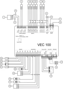
Figure 6: Changeover bypass wiring diagram – VEC100
| Number | Description | Object name (if given) |
| 1 | Economizer Damper Output (optional) | MAD-O |
| 2 | Supply fan output (to fan VFD) | SF-O |
| 3 | Supply fan command (to fan VFD) | SF-C |
| 4 | Compressor stage 1 command | COMP1-C |
| 5 | Reversing valve 1 command | REV1-C |
| 6 | Compressor stage 2 command | COMP2-C |
| 7 | Reversing valve 2 command | REV2-C |
| 8 | Supplemental heat command | SUPHTG-C |
| 9 | 24 V HOT to damper motor | n/a |
| 10 | 24 V COM to damper motor | n/a |
| 11 | 24 V COM | n/a |
| 12 | 24 V HOT | n/a |
| 13 | From last device | n/a |
| 14 | To next device | n/a |
| 15 | Zone humidity sensor – monitor only (optional) | ZN-H |
| 16 | Return air CO2 Range: 0 ppm to 2,000 ppm, 0 VDC to 10 VDC | RA-CO2 |
| Number | Description | Object name (if given) |
| 17 | Return air temperature sensor | RA-T |
| 18 | Outside air temperature sensor Note: This is a required sensor if the VEC100 controls the economizer. Position the sensor in a shaded area on the north side of the building. | OA-T |
| 19 | Discharge air static pressure sensor Range: 0 in. W.C. to 5 in. W.C., 0 VDC to 5 VDC | DA-P |
| 20 | Discharge air temperature sensor | DA-T |
| 21 | Condensate alarm | COND-A |
| 22 | Supply fan status (air proving switch, optional) | SF-S |
| 23 | Purge input (optional) | PURGE-S |
| 24 | Filter status (optional) | FILTER-S |
Table 4: Changeover bypass wiring diagram
VAV wiring diagram
| Number | Description | Object name (if given) |
| 1 | Economizer Damper Output (optional) | MAD-O |
| 2 | Supply fan output (to fan VFD) | SF-O |
| 3 | Supply fan command (to fan VFD) | SF-C |
| 4 | Compressor stage 1 command | COMP1-C |
| 5 | Reversing valve 1 command | REV1-C |
| 6 | Compressor stage 2 command | COMP2-C |
| 7 | Reversing valve 2 command | REV2-C |
| 8 | Supplemental heat command | SUPHTG-C |
| 9 | 24 V HOT to damper motor | n/a |
| 10 | 24 V COM to damper motor | n/a |
| 11 | 24 V COM | n/a |
| 12 | 24 V HOT | n/a |
| 13 | From last device | n/a |
| 14 | To next device | n/a |
| 15 | Zone humidity sensor – monitor only (optional) | ZN-H |
| 16 | Return air CO2 Range: 0 ppm to 2,000 ppm, 0 VDC to 10 VDC | RA-CO2 |
| Number | Description | Object name (if given) |
| 17 | Return air temperature sensor | RA-T |
| 18 | Outside air temperature sensor Note: This is a required sensor if the VEC100 controls the economizer. Position the sensor in a shaded area on the north side of the building. | OA-T |
| 19 | Discharge air static pressure sensor Range: 0 in. W.C. to 5 in. W.C., 0 VDC to 5 VDC | DA-P |
| 20 | Discharge air temperature sensor | DA-T |
| 21 | Condensate alarm | COND-A |
| 22 | Supply fan status (air proving switch, optional) | SF-S |
| 23 | Purge input (optional) | PURGE-S |
| 24 | Filter status (optional) | FILTER-S |
Table 5: VAV wiring diagram
Commissioning the system
To activate the outputs and verify system operation, navigate to the Commissioning menu, change Start Commissioning to Trigger, and adjust outputs individually.
The following table describes the Details > Service > Factory menu options.
| Object or parameter | Description | Adjustable | Defaults | Enum set or range |
| Number of Heat Pump Stages Installed | Sets the number of heat pump stages installed. | Adjustable | 2 | 0 to 2 |
| Supplemental Heat Installed | Sets whether supplemental heating is installed. | Adjustable | No | 0 = No 1 = Yes |
| Economizer Installed | Sets whether the economizer is installed. | Adjustable | No | 0 = No 1 = Yes |
| Air Proving Switch Setup | Selects the type of setup for airflow proof. | Adjustable | None | 0 = Fan Status Device 1 = Duct Static Pressure Sensor 2 = None |
| Runtime Equalization | Enables the device based on runtime. | Adjustable | No | 0 = No 1 = Yes |
| OAT Cooling Lockout Temperature | Sets the temperature at which outside cooling lockout occurs. | Adjustable | 50°F (10°C) | 0°F to 100°F (-18°C to 38°C) |
| Economizer Minimum Position Setpoint | Sets the minimum outside air damper position. | Adjustable | 20% | 0% to 100% |
| Rooftop Controller Type | Sets the controller type to changeover bypass or VAV. | Adjustable | Changeover Bypass | 0 = Changeover Bypass 1 = VAV |
| Variable Speed Drive | Sets whether the VEC100 controls a VFD fan instead of a bypass damper when the rooftop controller type is set to changeover bypass. | Adjustable | False | 0 = False 1 = True |
| Supply Air Temperature Alarm Offset | If SAT is not in this value range, the SAT alarm delay starts. Examples: If the supply air setpoint is 55°F and this is set to 5°F, then the supply air must be under 60°F, or the delay timer starts. If the supply air setpoint is 110°F and this is set to 5°F then the supply air must be above 105°F, or the delay timer starts. | Adjustable | 5 delta °F (2.78 delta °C) | 0 delta °F to 25 delta °F (0 delta °C to 14 delta °C) |
| Supply Air Temperature Alarm Delay | Sets the amount of time that must pass before the SAT alarm occurs. | Adjustable | 20 min | 0 min to 120 min |
| Cancel ASCD Timers | Resets the minimum on and off timers. | Adjustable | False | 0 = False 1 = True |
| Demand Ventilation Feature | Enables or disables the demand ventilation feature. | Adjustable | Off | 0 = Off 1 = On |
| Reversing Valve Config | Sets the reversing valve for heating or cooling | Adjustable | On for Clg | 0 = On For Htg 1 = On For Clg |
| Condensate Alarm | If you set this parameter to Yes, the condensate alarm shuts down the whole system. | Adjustable | No | 0 = No 1 = Yes |
Table 6: Details : Service : Factory
Product warranty
This product is covered by a limited warranty, details of which can be found at www.johnsoncontrols.com/buildingswarranty.
Software terms
Use of the software that is in (or constitutes) this product, or access to the cloud, or hosted services applicable to this product, if any, is subject to applicable end-user license, open-source software information, and other terms set forth at www.johnsoncontrols.com/techterms. Your use of this product constitutes an agreement to such terms.
Single point of contact
| APAC | Europe | NA/SA |
| JOHNSON CONTROLS | JOHNSON CONTROLS | JOHNSON CONTROLS |
| C/O CONTROLS PRODUCT MANAGEMENT | WESTENDHOF 3 45143 ESSEN | 507 E MICHIGAN ST MILWAUKEE WI 53202 |
| NO. 32 CHANGJIJANG RD NEW DISTRICT | GERMANY | USA |
| WUXI JIANGSU PROVINCE 214028 | ||
| CHINA |
Contact information
Contact your local branch office: www.johnsoncontrols.com/locations
Contact Johnson Controls: www.johnsoncontrols.com/contact-us
![]()


