
![]()
CONTROLS
KITS AND ACCESSORIES
508137-01 3/2021
Supersedes 506693-02
LonTalk® Module Kit
INSTALLATION INSTRUCTIONS FOR
LonTalk® MODULE (54W27) USED WITH COMPATIBLE ROOFTOP UNITS

![]() CAUTION
CAUTION
Electrostatic discharge can affect electronic components.
Take precautions during unit installation and service to protect the unit’s electronic controls. Precautions will help to avoid control exposure to electrostatic discharge by
putting the unit, the control and the technician at the same electrostatic potential. Neutralize electrostatic charge by touching hand and all tools on an unpainted unit surface
before performing any service procedure.
![]() IMPORTANT
IMPORTANT
Improper installation, adjustment, alteration, service or maintenance can cause personal injury, loss of life, or damage to property.
Installation and service must be performed by a licensed professional installer (or equivalent) or a service agency.
![]() IMPORTANT
IMPORTANT
When adding this module to an existing M2 Unit Controller, the M2 firmware must be v7.07 or higher.
Look on LennoxPros.com for the latest firmware, or call Lennox technical support at 800-453-6669 for firmware update information.
General
The LonTalk® module allows communication between the Lennox M2, M3, and M4 unit controllers and a LonWorks® network. The module is LonMark® certified to design
guidelines version 3.4.
For assistance, contact Lennox Technical Support at 800453-6669.
Installation
![]() IMPORTANT
IMPORTANT
A small flat-head screwdriver is required to connect the communication wire to the SmartWire connector.
- Remove power to the unit.
- Open the compressor access doors.
- Plug the LonTalk module onto the M2, M3, or CORE Unit Controller (M4). Guide pins will align the module with the Unit Controller connector.
- Connect the LonTalk SmartWire connector.


- Upon powering up the unit controller, the following is applicable:
PRODIGY M2 UNIT CONTROLLER
This controller will automatically recognize the LonTalk module and begin communications provided the network as been correctly configured.
To configure the LonTalk Network, go to: SETTINGS > CONTROL = LONTALK PRODIGY M3 UNIT CONTROLLER
To enable the LonTalk module, go to: SETUP > INSTALL and run the setup wizard.
When Configuration ID 1 appears on the screen, configure position 5 as L. This will enable the LonTalk module.
To configure the LonTalk Network, go to:
SETUP > NETWORK INTEGRATION = LONTALK LENNOX® CORE UNIT CONTROLLER (M4)
To enable the LonTalk module,
- Go to RTU MENU > SETUP > INSTALL
- When CONFIGURATION ID 1 appears on the screen, configure position 5 as This will enable the LonTalk module.
- To configure the LonTalk Network
Go to RTU MENU > NETWORK INTEGRATION > NETWORK SETUP WIZARD = LONTALK
Operation and Functional Description
LONWORKS NETWORK CONNECTION
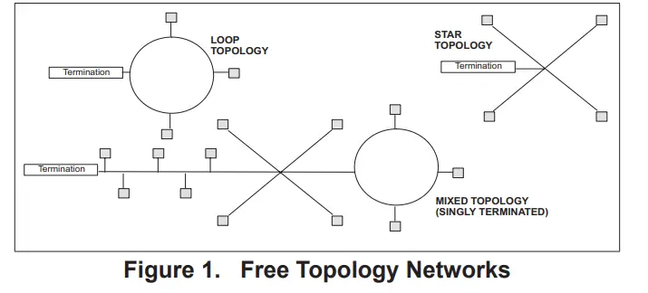
The LonTalk module has an FTT-10A Free Topology Transceiver for network communication. The FTT-10A transceiver network supports free topology wiring and will accommodate bus, star, loop, or any combination of these topologies. The module can be located at any point along the network wiring. This capability simplifies system installation and makes it easier to add nodes when required.
LONWORKS NETWORK CABLE
The LonWorks TP/FT-10 network requires Echelon qualified twisted-pair communication cables such as Belden 8471 or NEMA Level 4 cables. Other Echelon approved equivalent cables may also be used depending on the application. The Belden 8471 or NEMA Level 4 cables are rated for plenum use.
The network cable should be routed using best practices to avoid induced noise. Do not route alongside power lines, or in proximity to high voltage or high-frequency devices, such as ignition controls and variable frequency drives. The average temperature of the wire must not exceed 131°F (55°C).
NETWORK LIMITS (FREE TOPOLOGY)
The LonWorks TP/FT-10 free topology network is limited to a maximum of 64 nodes per segment. The maximum total bus length and the maximum node-to-node length is1640
ft. (500 m) for Belden 8471 or NEMA Level 4. Maximum lengths are less for other smaller wire size cables.
Only one termination circuit module is required at any location along with the network. Refer to Echelon LonWorks FTT- Transceiver User’s Guide for additional details.
FREE TOPOLOGY NETWORKS
Free topology segments require a termination circuit for proper performance. Only one termination circuit module is required at any location along with the network.
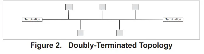
NETWORKS LIMITS (DOUBLY–TERMINATED TOPOLOGY)
The LonWorks TP/FT-10 Doubly-Terminated topology network is limited to a maximum of 64 nodes per segment. The maximum total bus length is 5000 feet (1524 meters) for Belden 8471 or NEMA Level 4. Maximum bus lengths are less for other smaller wire-size cables. The maximum stub length is 9.8 ft. (3 m). In many cases, this bus network is connected in a daisy chain manner where the bus is wired directly to each node, so the stub length is zero.
Two field-provided termination circuit modules are required for each segment. One must be located at each end of the network.
NETWORK BUS TERMINATION
To install the network bus terminal module 37X75, connect the brown and yellow wires to the network bus that requires single termination and connect the brown and orange wire to the network bus that requires double termination. The unused termination module wire must be covered with a wire nut to prevent potential grounding problems.
NETWORK INTEGRATION
A network configuration tool such as LonMaker® is required to commission the LonWorks network. Press the service button on the LonTalk module to generate a service message that contains the Neuron ID.
Other commissioning methods may be used. The Neuron address is located on the LonTalk module. An External Interface File (XIF) is available for configuration prior to installation.
PRODIGY RESET
The Prodigy unit controller may be reset using nviRequest with enumeration RQ_RESET sent to NodeObject function block.
ZONE OR ROOM SENSOR CONTROL
In order to use room temperature setpoints, the Prodigy unit controller must be configured for Zone Temperature control mode. This may be done through the Prodigy display.
PRODIGY – M2 ZONE SENSOR CONTROL CONFIGURATION
PROCEDURE
In order to use nviSpacelAQ, nviSpaceRH, or NVI SpaceTemp, the Prodigy M2 unit controller must be configured.
- Go to the M2 Unit Controller user interface.
- Use the select button to enter the menu, and use the up/ down buttons to scroll through the options.
- Go to SETTINGS > CONTROL > LONTALK > CONTROL MODE and select ZONE for the Zone Temperature control mode.
This is the same as setting the Prodigy ECTO (Electronic Config To Order) parameter 6.01 to a value of 1.
PRODIGY – M3 ROOM SENSOR CONTROL CONFIGURATION
Procedure
In order to use nviSpacelAQ, nviSpaceRH or nviSpaceTemp, the Prodigy M3 unit controller must be configured.
Go to the M3 Unit Controller user interface.
- Go to SETTINGS > GENERAL > CONFIGURATION ID 1 and verify or change position 5 is set to
- Go to: SETUP > NETWORK INTEGRATION and set to TALK.
- Set CONTROL MODE to either MONITOR ONLY or ROOM SENSOR. If ROOM SENSOR is selected, then enabled the applicable sensors (CO2, RH or TEMP).
CORE UNIT CONTROLLER (M4) ROOM SENSOR CONTROL
CONFIGURATION PROCEDURE
In order to use nviSpacelAQ, nviSpaceRH or nvi SpaceTemp, the CORE unit controller must be configured.
Go to the LENNOX® CORE SERVICE APR
- Go to RTU MENU > INSTALL > CONFIGURATION ID 1 and verify or change position 5 is set to L.
- Go to SETUP > NETWORK INTEGRATION and set to
- Set CONTROL MODE to either MONITOR ONLY or ROOM SENSOR. If ROOM SENSOR is selected, then enabled the applicable sensors (CO2, RH or TEMP).
DATA UPDATE RATE
If nviSpaceTemp, nviOutdoorTemp, nviSpaceRH, or nviSpacelAQ are used, the data needs to be updated within five minutes to be valid.
LANDMARK FUNCTION PROFILES
The Prodigy LonTalk module contains two LonWark functional profile function blocks, space comfort controller-rooftop and discharge air controller. It also contains a Lennox specified functional block, a virtual function block containing the network configuration variables and a node object.
NVI DUPLICATION
nviOccSchedulel, (in sccRooftop), and nviOccSchedjle, (in dischargeAirCont), are duplicate network variable inputs and only one should be used.
Also, nviFanSpeedCmd and nviSupFanCap have the same functionality and only one should be used.
Both nviSetpoint and nviHCSetpoints change the effective temperature setpoints and only one of them should be used.
DEVICE FUNCTION BLOCKS
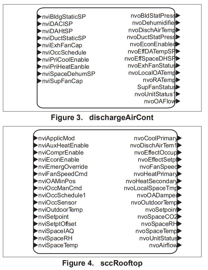 | 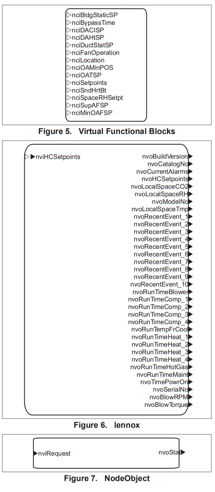 |
Table 1. Network Variables (Sorted Alphabetically)
| SNVT Name | SNVT Index | SNVT Name | SNVT Index | SNVT Name | SNVT Index |
| nciBldgStaticSP | 40 | nviSetpoint | 8 | nvoOAFlow | 101 |
| nciBypassTime | 104 | nviSetptOffset | 9 | nvoOutdoorTemp | 35 |
| nciDACISP | 38 | nviSpaceDehumSP | 53 | nvoRATemp | 63 |
| nciDAHtSP | 39 | nviSpacelAQ | 20 | nvoRecentEvent_1 | 71 |
| nciDuctStatSP | 41 | nviSpaceRH | 19 | nvoRecentEvent_2 | 72 |
| nciFanOperation | 66 | nviSpaceTemp | 7 | nvoRecentEvent_3 | 73 |
| nctocation | 1 | nviSupFanCap | 48 | nvoRecentEvent_4 | 74 |
| nciMinOAFIowSP | 43 | nvoAirflow | 100 | nvoRecentEvent_5 | 75 |
| nciOAMinPos | 5 | nvoBldgStatPress | 60 | nvoRecentEvent_6 | 76 |
| nciOATSP | 42 | nvoBlowRPM | 102 | nvoRecentEvent_7 | 77 |
| nciSetpoints | 4 | nvoBlowTorque | 103 | nvoRecentEvent_8 | 78 |
| nciSndHrtBt | 0 | nvoBuildVersion | 86 | nvoRecentEvent_9 | 79 |
| nciSpaceRHSetpt | 6 | nvoCatalogNo | 85 | nvoRecentEvent10 | 80 |
| nciSupAFSP | 67 | nvoCoolPrimary | 32 | nvoRunTimeBlower | 99 |
| nviApplicMode | 22 | nvoCurrentAlarms | 70 | nvoRunTimeComp_1 | 88 |
| nviAuxHeat Enable | 15 | nvoDehumidifier | 65 | nvoRunTimeComp_2 | 89 |
| nviBldgStaticSP | 50 | nvoDischAirTem1 | 29 | nvoRunTimeComp_3 | 90 |
| nviComprEnable | 14 | nvoDischAirTemp | 54 | nvoRunTimeComp_4 | 91 |
| nviDACISP | 46 | nvoDuctStatPress | 57 | nvoRunTimeFrCool | 92 |
| nviDAHtSP | 47 | nvoEconEnabled | 61 | nvoRunTimeHeat1 | 95 |
| nviDuctStaticSP | 45 | nvoEffDATempSP | 56 | nvoRunTimeHeat_2 | 96 |
| nviEconEnable | 16 | nvoEffectOccup | 26 | nvoRunTimeHeat_3 | 97 |
| nviEmergOverride | 17 | nvoEffectSetpt | 25 | nvoRunTimeHeat_4 | 98 |
| nviExhFanCap | 49 | nvoEffSpaceDHSP | 64 | nvoRunTimeHotGas | 93 |
| nviFanSpeedCmd | 13 | nvoExhFanStatus | 59 | nvoRunTimeMaint | 87 |
| nviHCSetpoints | 68 | nvoFanSpeed | 28 | nvoRunTimePowrOn | 94 |
| nviOAMinPos | 21 | nvoHCSetpoints | 69 | nvoSerialNo | 84 |
| nviOccManCmd | 11 | nvoHeatPrimary | 30 | nvoSetpoint | 27 |
| nviOccSchedule | 44 | nvoHeatSecondary | 31 | nvoSpaceCO2 | 36 |
| nviOccSchedulel | 10 | nvoLocalOATemp | 62 | nvoSpaceRH | 34 |
| nviOccSensor | 12 | nvoLocalSpaceCO2 | 81 | nvoSpaceTemp | 23 |
| nviOutdoorTemp | 18 | nvoLocalSpaceRH | 82 | nvoStatus | 3 |
| nviPriCool Enable | 51 | nvoLocalSpaceTmp | 37 | nvoSupFanStatus | 58 |
| nviPriHeatEnable | 52 | nvoModelNo | 83 | nvoUnitStatus | 24 |
| nviRequest | 2 | nvo0ADam per | 33 | nvoUnitStatus1 | 55 |
Table 2. Network Variable Definitions
| Index | SVT N81119 | SVT TYPO | Functional Block | Send heartbeat | A ppl lCatlOn DeeCtiptlOn |
| 0 | nciSndHrtEll | SeNT_Ime_sec | Virtual Film tonal Brea | — | · Avatar of 0(zero). We off the send heal beat breast · Values be been .01 seconds and 104ffe treated as 10 seconds. · Ten (10) seconds is the mailman heartbeat *waled rate.) |
| 1 | colocation | SVT let oleo | Virtualock Roc tonal St | Location label Meng. | |
| 2 | SNVT_ctuesuest | NodeOtyect | — | ·Request an operation a mode for a Motional block will a device. requests as: RONORMAL. RO_UPDATE_STATUS. RQ REPORT_ · RQ RESET and RQ CLEAR RESET are suppated for the NaleOtetot Anatol brat to reset the Pricbgy conirceet. | |
| 3 | nvoStatus | SWr_ot_stabs | NxleCtyect | No | Repots the stylus bra f stabile! dock. |
| 4 | noiSebants | SVT fornp_setot | Virtual Febbast No* | — | · Sets default zone temperature setting for the unit. · Vaktranges are 40-95•F. ·The cooing setwinb must be above the ccasswacfmg heating sent by the unify aubchangeover dead-band (3•F default). ·The standby setpoints as not used by the Appicaka |
| 5 | ncitJAMnPos | SWTkwpercent | Virtual Functional Stock | — | · Sets the outdoor* dancer Strain position. ·Used M modes were outdoor *ventilation Sr eared. except when nviOAPWce if wad. |
| 6 | nciSpeceRHSetpt | SNP/T .ev percent | Virtual Roc tonal back | — | · Defines a deburnktecalca serpent for Me controlled space. · Not used when neSpaceDebumkISP is valet. |
| 7 | nviSpaceTerro | SMILlernp_p | sc.:Rooftop | — | · Stop led range: 36254o-100•F. · Mail be updated %ebb 5 nimble,. · Must be enabled %eh ECTO 5.27 (Feature not *Sable ei Prodigy 20 Meat release). |
| 8 | nv.Setxxnt | Stni_leinp j) | sccRcolle: | – | · Used beet tie temperature setpoints fa the occupied mode. NOTE: The unoccupied spawns are not changed. · I a yak, value is not present tie appropriate select% as configured ei noSetweds vat be used. The “syrnnwerbal method– is used. · The efface..e healkoct help:Mte for the occupied node me derived from viewpoint plus / minus had the occupied headbands yet Prodigy ECT06.15 elfecive_occupiedcod • mtSetpokil +0.5 (clengener_deedband ) efleciveoccupiedfieet= miSetpcint -0.5 (cAangeoner_deadband) |
| 9 | nviSe veers | SNYTIampp | scroop | — | Used lo shift the effective occupied lemperakse sellers by adding neSelp1011sel b the anent satanic |
| 10 | nviOccSonedulat | SNYTbdevent | scroop | — | Only arrant stale occupancy models were swooned. |
| 11 | nytOccManCnx1 | SNYT_occupency | scroop | — | Used to command be Space Canton Conttler into oillerent occupancy node |
| 12 | nviOccSenta | SNYT_occupency | scroop | — | Used to Mcketethe; the essence of occupants in tie contracted space. |
| 13 | nviFariSpeedCrnd | SNVT_verith | scroop | — | Used to set the unite Mower speed. |
| 14 | nviComprEnatte | SNVT Mahn | sccRoollop | Used lo dater commit:4 operation. | |
| 15 | nviAuxHeatEnatie | SVT swish | so rooftop | — | Used to cleat* anctiary heel operation. |
| 16 | nviEconEnette | SENT sw=an | SCCRcollop | Used lo enabled dater economizer operator. | |
| 17 | SNVT_hvacemag | sccRoolto; | _ | · Used to command the device at different emergency modes. ·Swooned eturnerallons:EMERG NORMAL EMERGPRESSUFIZE EMERG DE PRESSUReE EMERG PURGE EMERG_SHUTDOV*4 EMERG_NUL | |
| 18 | nvrNiloaTerno | Sleafernp_p | socRooftop | — | · Supported range: -30.6 b 131,F. · Input must be updated! Shin 5 minutes. |
| 19 | nviSpaceRH | SWilev_percent | sccRooflop | — | · bout must be updated Lett 5 Stubs. · Must be enabled velhECTO 5.27 |
| R | nviSpace1A0 | SWT_ppm | sccRcoftop | — | · Supported range: 0 to 2,000 Mee · We mule be updated vathit 5 minutes. · Must be enabled x4th ECTO 127 (Feast not available in Prodigy 20 mien rebate). |
| 21 | nviOAMnPos | SWT_Mv_percent | sccRooftop | · Used to provide a dynamic narlirriuni post., seawall for an OuteXt as damps. · Wien wad it all supersede nclOAMInPce. | |
| 22 | nviAppe:Made | SVT hvac_rmde | so rooftop | — | ·Used legit IT trip mode. Swooned values: AUTO. HEAT ONLY. POOL· Must be updated weir the 120 rules, if used. |
| 23 | nvoSpaceTemp | SNVT_Iarp_p | sccRcc41:9 | Yes | ·The output S is the effective space temperature value that I control ks using. · The support range’s 38 b 100T. |
| 24 | nvoUrstStatus | SNVOivac_status | Scrooby | Yes | Repots lie controller status. |
| 25 | nvoEffedSepl | SNVT_terrp_p | sccRoof bp | Yes | Repots Pe current effective space temperature setpoint |
| 26′ | nvoEffectOccup | SNVLoccupancy | scollop | No | Reports are effective occupancy able (see Appendix B). |
| 27 | nvoSetpcMil | SVT terrp_p | sccRoof bp | No | Reports Pe current special without the app aka of nviSetplOffset |
| 28 | rwoFanSpeed | SNVItseltch | sccRcofIcg | Yes | Reports the current unit blower speed |
| 29 | rwc0ischArTernp | SNVItterrp_p | CCRC of kg | No | ·Repots tie discharge temperature value. · Supported range. -8 b +163°F. |
| 30 | rwoHealPrimay | SNVItlev_percenl | CCRC of lop | Yes | Reports the current pinky heal outul value. |
| 31 | nvoHeatSeccodaty | SVT lev_percem | sccRooltop | Yes | Reports fie current secondary heal output value (heal pumps coy). |
| 32 | nvoCcoPrimaty | SNVItlev_percenl | CCRC of kg | Yes | Reports the current ccceing output %due. |
| 33 | nvo0ADamper | SVT lev_percent | sccRoof bp | Yes | Reports fie current outdoor as dancer post ion. |
| 34 | nvoSpaceRH | SNVIllev_percent | scollop | Yes | Reports to effective space relative hun*Iffy *Due. |
| 35 | mcOuldocifemp | SVT terrp_p | scollop | Yes | · Reports the &leave outdo:. temperature value. · Supported range. -30 b •130T. |
| 38 | nvoSpaceCO2 | SNVT_pyn | CCRC of Icy | Yes | · Repot; the effective space is eaten dioxide W. · Supported range.° b 2.000 ppm. |
| 37 | moLocalSpacermp | SNVf_temp_p | scollop | Yes | · Report the space temperate moused by the Pc* eke sauce. · Suppyled range. 38 b 100T. |
| 38 | noDACISP | SNVT_Ierrp_p | Virtual Funacnal Block | — | · Sets the debut! discharge air cooking temperate set pont ·Supported range: 40 b 100T. |
| 39 | noDAHtSP | SNVT_ternp_p | Virtual Fundaial Block | — | · Sets the default discharge air heating temperature selpc.e. · Supported range: 60 b 1407. |
| 40 | noCiuttSPISP | SNVT_press_p | Virtual Functicaal Block | — | · Sets re-debut! duct Pak pressure sal pont ·Supported range: 0 lo 1245Pa. |
| 41 | nciOATSP | SNVT_terrp_p | Virtual Functional Block | — | · Sets tie outdoes’ sir temperature special loanable free-cooking for units with escapades. · Supported range:40 b 75T. |
| 42 | noBldgSlakSP | SNVf_press_p | Virtual Functional Block | — | ·Sets tie debit, basking slat pressure set pool for exhaust miter & ·Supported range -124.5 b 1245 Pa. |
| 43 | noMerOARowSP | SNVf_flow | dual Virt Fundicoal Brick | — | ·Set to delauel outdoor at lbw for SmanAalbw Ty enabled roof by units. · Supported range -0 b 150cfmAco · Mulkoly the CFMAco value term Mirage of fie unit b drove be value in CF M. |
| 44 | NEC schedule | SVT tote** | dischargeArCcril | — | Only the current slate is supported. |
| 45 | nvOudSlaticSP | SNVT_Ixess_p | ckschargeArCcal | — | · Sets re dud abbe pressure afloat. ·Suspected range:0 b 1245Pa. |
| 48 | neDACISP | SNVT_Ierrp_p | dischargeAirCon1 | — | · Selo tie discharge* cooking temperature selp*A · Swiveled range:40 b 100T. |
| 47 | nv0AHSP | SNVT_Ierrp_p | ckschargeASCcol | — | · Sets lie discharge* heating tempera* setpoint ·Supported range: 60 b 140W. |
| 48 | nviSupFanCap | SVT lev_percen1 | cbschargeAtectt | — | Sets the unit’s blower speed. |
| 49 | msExhranCaP | SNVT_Iev_percen1 | duchargeArCcol | — | Set the unit’s exhaust fan speed. |
| 50 | neEllOgStalcSP | SNVT_press_p | ckschargeketcril | — | – Sets re building abbe pressure sepont kr exhaust carol. – Supply range -124.5 to 124.5 Pa. |
| 51 | menCcolEnable | SNVT snitch | cbschargeArCcm | — | Used lo disable cant: ream’ opera. |
| 52 | nviPnHeatEnable | SNVT svalch | dtschargeks-Ccal | — | Used to disable primary heating operation. |
| 53 | neSpaceDehurnSP | SNVT_Iev_percenl | duchargeArCcol | — | Set the dehurnidficabco RH sepcinl. |
| 54 | mcDschArTenp | SNVT_Ierpp | scRcolop | no | ·Repot te dschage *terfamatue. ·Supported range: -8 b 131T.. |
| 55 | rwoUnitStalus1 | SNVT_hvac_stalus | duchargeArCoil | Yes | Reports be cetera* status. Same as nvoUnitStalus in sccRcollop functico block. |
| 56 | nvoEfIDATempSP | SNVf_ternp_p | dechargeArCcal | Yes | Reports fie effective discharge as a temperate percent |
| 57 | nvoDuctSlatPress | SN VT _roes s_p | dischargeArCcal | Yes | · Report the duct slack pressure. · Suppyled range: 0 b 1245Pa. |
| 58 | nvoSupFariStatus | SNVLswecti | cbschargeArCcm | Yes | Reports um blower speed. |
| 59 | nvoExhFanStalus | SNVT_svelch | discharge-Cyril | Yes | Reports exhaust fan speed. |
| 60 | nvoEconEnatled | SNVT_seetch | dischargeArCcol | Yes | Reports tee-access status of economizing |
| 61 | mollIdg.SiatRess | SNVT_press_p | dischergeturCont | Yes | · Report the budding static pressure. · Suspected range: -124.5 to +1245 Pa. |
| 62 | nvoLoctiOATetrp | SFrtetrp_p | dechergeturCont | YeS | · Reports boat’ meastsed cutter temperature. · Supported range: -30 to +13ot |
| 63 | nvcRATemp | SNVT tempt’ | disc hargeAirOont | Yes | · Ribcvls eff Galva glum ars temPeralure. · Supported range: -810 +1631. |
| 64 | moEffSpaceCHSP | SNVT_press_p | clochargeAkCcnt | Yes | Report effedne *save humidity seeing for clehutradifican. |
| 85 | moDelumktrier | SWT switch | dechargsfurCent | Yes | Report status of dehuniddicenn cymbal. |
| 66 | nciFenOperafen | SCPTbnOperaticn | Vaal F unapt* Block | — | Sets the operation male for the unit *cam Outing occupied slats |
| 67 | noSupAFSP | UNVT SupPF_Sps | Verbal Funcional Back | — | · Set the defaultAirflow stenos for a Smartairllowns enabled roof Count in 10 sec Una. · Fa vied ranges please refer b theAppendock |
| 68 | insHCSebanis | SWT temp semi | Lennox | — | · Valkil raves are 4043451 (ceding). · The cooing setpoints must be above the corresponda hoeing sent by the units Aulochangeerva Deadband (ECTO 615. 31-cleavage or PICOicy 2.0 Pararneex 152). · The standby set pants ate not used by the Application |
| 69 | nvonGSacints | SVT Iterp_selpt | Lennox | No | · Reports zone “Immature setpoints. · Standby setpoints a not teed and are returned %Mt to unoccupied values. |
| 70 | nvoCurentAlemis | UNVT_arrentNarrns | Lennox | Yes | Reports currently active alarm codes. |
| 71 | moReceneamm_l | UNVT event | Lennox | Yes | Reams most recta Sinn Cole. |
| 72 | moRecenEven1_2 | UNVT event | Lennox | No | Reams second most menu &M. |
| 73 | nvoRecenlEvent_3 | UNVIlevent | 1011110X | No | Report alarm. |
| 74 | nvoReoenlEven1_4 | UNVIlevent | Lennox | No | |
| 75 | nvoRecenEvenl_5 | UNVT_ewsnt | !sonar | No | |
| 78 | nvoRecenlEvent_6 | UNVT_event | Lennox | No | |
| 77 | moRecenEvent_7 | UNVT event | lennox | No | |
| 78 | nvoReceellEvent_8 | UNVT event | lennox | No | |
| 79 | nvORICe11Evillnl9 | UNVIlevent | kenos | No | |
| 80 | meReCettlEwIn410 | UNVT event | Lennox | No | |
| 81 | molocalSpaceCO2 | SVT _ppm | lemma | No | · REpats locally measured apace carbon der** level. · Suspected range: 0 to 2.000 ppm. |
| 82 | moiccalSpaceRH | save 1ev_Cercen | bran | No | Report IcceY measured space relative tumidly level. |
| 83 | nvoMoceiNo | SWT s V_asc | Lennox | No | Report unit model neater. |
| 84 | NV senate, | SWT staw | Lennox | No | Repaid unit serial number. |
| 85 | nvoCatelegNo | SWT sv_asc | Lennox | No | Report unit catalog number. |
| 86 | nvoStuildVersbn | SNYT s v_asc | bows | No | Report flarraetevetson siring. |
| 87 | moRunTinebtent | UNVItmairtnnimes | Lennox | No | Repot air filer. Mosta be and INlamp mn-taws. |
| 88 | nvoRunTirner..cap_l | UNVIlminutes_cycles | Wax | No | Report nut-same and cycle count for cars:testa 1. |
| 89 | nvoRtmTmeCcep_2 | UNVT_rrenufes_cycles | Lennox | No | Renege run-bme and cycle count for canpressa 2. |
| 90 | nvoRunTmeCarp_3 | UNIVT_mriules_cycles | Lennox | No | Report run-bme and cycle count for empresses 3. |
| 91 | nvoRunTmeCarp_4 | UNVT_mates_cycles | Lennox | No | Report nut-ere and cycle count for cars: gasser 4. |
| 92 | nvoRunTrneFrOsol | UNVT rrinuies_cycles | Lennox | No | Report 111141110 and cycle count br free cooing operation. |
| 93 | nvoRunTenelistGas | UNVT rrinuies_cycles | Lennox | No | Reports 111141110 and cycle count to hot gas Mimes dehunelfIcatiOn. |
| 94 | nvoRunTimelaavrOn | UNVIIrrinutes_cycles | kenos | No | Report run-frne and cycle count for unit poems cc. |
| 95 | nvoRunTineHeat_1 | UNVIIninutes_cycles | Lennox | No | Report nn-one and cycle count for heat stage 1. |
| 98 | nvoRtmTmeHeat_2 | UNVT_rnnuies_cycles | Lennox | No | Report run-lime and cycle count for heat stage 2. |
| 97 | nvoRunTmeHeat_3 | UNWT_mrittles_crles | Lennox | No | Rocca run-lime and cycle count for heal stage 3. |
| 98 | moRunTineHeat 4 | UNVT rrinuies_cycles | bows | No | Report 1111-1010 and cycle count for heat stage 4. |
| 99 | moRunTrneElkwer | UNVT rrinuies_cycles | Winos | No | Reams 1111-1010 and cycle count to Meer. |
| 100 | overflow | SNYT flow | seRookop | Yea | · Reports the amount of current supply* low · Supported range: 0480 admin |
| 101 | nvo0A1low | SVT flow | clischarceeirCcal | Yes | · Reports the amount of cutloco airflow. · Supported range: 0490 min |
| 102 | moBlovARPM | SNVT_rpm | 1011110X | Yes | · Risme the blower moor weed · Suppabd range: 01500 rpn |
| 103 | nvoBlowTorque | SNVTlev_percent | Lennox | Yes | • Reports the PWM of an ECM blower motor. • Supported range: 0 – 100 % |
| 104 | nciBypassTime | SNVT_time_min | Virtual Function Block | – | • This configuration defines the maximum amount of time that the controller can be in the bypass (occupancy) mode following a single bypass request from either a local (hardwired) bypass switch or nviOccManCmd. • Additional Bypass requests can restart the timer. |
| Table 3. Variable Type Definitions | |
| SNVT Type | Definition |
| SCPTfanOperation | fan_operation_t Enumeration, 1 byte Value Identifier Notes -1 (OxFF) HVF_NUL Invalid Value 1HVF_CYCLE Fan cycles with heating and cooling 2 HVF_CON_CYCLE Continuous in occu pied, cycles in occupied standby |
| SNVT_hvac_emerg | emerg_tEnumeration, 1 byte |
| SNVT hvac _mode | hvac tEnumeration, 1 byte |
| SNVT_hvac_status | typedef struct { hvac t mode; signed long heat_output_primary; signed long heat_output_secondary; signed long cool_output; signed long econ_output; signed long fan_output; unsigned short in alarm; } SNVT_hvac_status; |
| SNVT_lev_percent | Signed Long, 2 bytes Valid Type Range: -163.840 .. 163.830 Type Resolution: 0.005 Invalid Value: 32,767 (0x7FFF) |
| SNVT_occupancy | occup_tEnumeration, 1 byte |
| SNVT_ppm | Unsigned Long, 2 bytes Valid Range: 0 .. 65,535 Parts per Million (ppm) |
| SNVT_press_p | Signed Long, 2 bytes Valid Type -32768 .. 32,766 Pascals Invalid Value 32,767 (0x7FFF) |
| SNVT_str_asc | ASCII character string with NUL terminator 30 characters max, 31 bytes |
| SNVT_switch | typedef struct { unsigned value; signed state; } SNVT_switch; value: percentage of full scale, resolution 0.5% state: can either be -1 (NULL), 0 (OFF), or 1 (ON) |
| SNVT_temp_p | Temperature Signed Long 2 bytes Valid Range: -273.17 .. 327.66 Resolution: 0.01 Degrees Celsius Invalid Value: 32,767 (0x7FFF) |
| SNVT_temp_setpt | typedef struct { signed long occupied_cool; signed long standby_cool; signed long unoccupied_cool; signed long occupied_heat; signed long standby_heat; signed long unoccupied_heat } SNVT_temp_setpt; |
| SNVT_flow | Flow Volume Unsigned Long, 2 bytes Valid Range: 0 .. 65,534 lit/sec Resolution: 1 lit/sec Convert to CFM 1 cfm = 0.4719474432 lit/sec |
| SNVT_rpm | Revolutions per minute Unsigned Long, 2 bytes Valid Range: 0 .. 65,534 RPM Resolution: 1 RPM |
| SNVT_time_min | Elapsed Time Signed Long, 2 bytes Valid Range: 0 .. 65,535 Minutes Resolution: 1 Minute |
| SNVT_time_sec | Elapsed Time Signed Long, 2 bytes Valid Range: 0 .. 6,5535 Seconds Resolution: .01 Seconds |
| SNVT time stamp | typedef struct { signed long year; unsigned short month; unsigned short day; unsigned short hour; unsigned short minute; unsigned short second; } SNVT_time_stamp; |
| SNVT_tod_event | typedef struct { occup_t current_state; occup_t next_state; unsigned long time_to_next_state; }SNVT_tod_event |
| UNVT_currentA !arms | typedef struct { unsigned short AlarmCount; event_code_t AlarmCode1; event_codet AlarmCode2; event_code_t AlarmCode3; event_ cadet AlarmCode4; event_code_t AlarmCode5; event_code_t AlarmCode6; event_code_t AlarmCode7; }U NVT_currentAlarms; |
| UNVT event | typedef struct { event_code_t Event; struct EventStatus { unsigned reserved :1; unsigned currentlyActiveAlarm :1; unsigned UnitOffOnAlarm :1; unsigned reserved5bits :5; }; SNVT time stamp EventTime; };UNVT_event |
| UNVT_maint_run times | typedef struct { signed quad filter_time_minutes; signed quad belt_time_minutes; signed quad UV Jamp_time_minutes;}UNVT_maint_runtimes; |
| UNVT min utes cycles | typedef struct { signed quad minutes; signed quad cycles; }UNVT_minutes cycles; |
| UNVT_SupAF_Stps | typedef struct { unsigned long HeatSP; unsigned long HiCoolSP; unsigned long MHCooISP; unsigned long MLCooISP; unsigned long LoCoolSP; unsigned long VentSP; unsigned long SmokeSP; }UNVT_SupAF_Stps All the above parameters follow the same unit convention as SNVT flow. |
Network Configuration Parameter Implementation
The following table show which Prodigy ECTO (Electronic Config-To-Order) parameters are updated with Network Configuration Parameter (nci) parameter updates.
Parameters Refer to Prodigy Application Guide for ECTO details.
Table 4. Network Configuration Parameter to Prodigy M2
Electronic-Config-To-Order Parameter Relationships
| NCI | ECTO |
| nciBldgStaticSP | 8.20 |
| nciBypassTime | 6.06 |
| nciDACISP | 7.16 |
| nciDAHtSP | 7.10 |
| nciDuctStatSP | 0.16 |
| nciFanOperation | 6.17 |
| nciMin0AFlowSp | 10.17 |
| nciSupAFSP | HeatSP — 10.5 HiCoolSP — 10.2 MHCooISP— 10.4 MLCooISP — 10.3 LoCoolSP — 10.1 VentSP 10.6 SmokeSP — 10.7 |
| nciOAMinPos | 5.24 |
| nciOATSP | 6.26 |
| nciSetpoints | 6.02 — 6.05 |
| nciSpaceRHSetpt | 4.25 |
The following table shows which Prodigy 2.0 Parameters are updated with Network Configuration Parameter (nci) parameter updates.
Parameters Refer to Prodigy 2.0 Application Guide for
Parameter details.
Table 5. Network Configuration Parameter to Prodigy M3 and CORE (M4) Parameter Relationships
| NCI | Parameter |
| nciBldgStaticSP | 215 |
| nciBypassTime | 141 |
| nciDACISP | 180 |
| nciDAHtSP | 174 |
| nciDuctStatSP | 37 |
| nciFanOperation | 154 |
| nciMinOAFlowSp | 237 |
| nciSupAFSP | HeatSP — 13 HiCoolSP — 14 MHCooISP— 15 MLCooISP — 16 LoCoolSP — 17 VentSP 18 SmokeSP — 12 |
| nciOAMinPos | 132 |
| nciOATSP | 160, 161, 162, 163 |
| nciSetpoints | 137 – 140 |
| nciSpaceRHSetpt | 106 |
Supply Airflow Targets
The maximum and minimum values of Supply Airflow
Targets in CFM units are as below in CFM.
Table 6. Energence® A Standard and High-Efficiency Box Supply
Airflow Targets
| UNIT SIZE (A Boxes) | 36 | 48 | 60 |
| Maximum High-Speed Target and Heat Mode Target (480 CFM/ton) | 1450 | 1925 | 2400 |
| Minimum High-Speed Target (280 CFM/ton) | 850 | 1125 | 1400 |
| Minimum Low-Speed Target (220 CFM/ton) | 650 | 875 | 1100 |
| Minimum Ventilation Target (150 CFM/ton) | 450 | 600 | 750 |
| Minimum Heat Mode Target Standard Gas Heat (S,W) | 975 | 975 | 975 |
| Minimum Heat Mode Target Medium Gas Heat (M, Q, U, Y) | 1125 | 1125 | 1125 |
| Minimum Heat Mode Target High Gas Heat Minimum (H, T, X, Z) | 1300 | 1300 | 1200 |
| Minimum Heat Mode Target High Gas Modulating Heat W1 (D) | N/A | N/A | 1300 |
| Minimum Heat Mode Target High Gas Modulating Heat W2 (D) | N/A | N/A | 1300 |
| Minimum Heat Mode Target Electric Heat | 1075 | 1275 | 1600 |
| Maximum Outdoor Airflow (150 cfm/ton) | 450 | 600 | 750 |
| Note: 1. Maximum Ventilation Target should be less than High-Speed Target or Heat Mode Target | |||
Table 7. Energence® A Standard and High Efficiency
Box Supply Airflow Targets
| UNIT SIZE (A Boxes) | 36 | 48 | 60 | 74 |
| Maximum High-Speed Target and Heat Mode Target (470 CFM/ton 3660; 390 CFM/ton 74) | 1400 | 1875 | 2350 | 2350 |
| Minimum High-Speed Target (300 CFM/ton) | 900 | 1200 | 1500 | 1800 |
| Maximum Low-Speed Target (280 CFMlton) | 850 | 1125 | 1400 | 1675 |
| Minimum Low-Speed Target (170 CFMlton 36-60; 140 CFM/ton 74) | 500 | 675 | 850 | 850 |
| Minimum Ventilation Target (170 CFMlton) | 500 | 675 | 850 | 1025 |
| Minimum Heat Mode Target Standard Gas Heat (B, S, W) | 975 | 975 | 975 | 975 |
| Minimum Heat Mode Target Medium Gas Heat (M, Q, U, Y) | 1125 | 1125 | 1125 | 1125 |
| Minimum Heat Mode Target High Gas Heat Minimum H, T, X, Z) | N/A | 1300 | 1300 | 1300 |
| Minimum Heat Mode Target High Gas Modulating Heat W1 (D) | N/A | 1250 | 1250 | 1250 |
| Minimum Heat Mode Target High Gas Modulating heat W2 (D) | N/A | 1500 | 1500 | 1500 |
| Minimum Heat Mode Target Electric Heat | 1075 | 1275 | 1600 | 1600 |
| Maximum Outdoor Airflow (150 cfm/ ton) | 450 | 600 | 750 | 900 |
| Note: 1. Maximum Ventilation Target should be less than High-Speed Target or Heat Mode Target | ||||
LonTalk Occupancy Signals and Blower Operation
This section describes how LonTalk occupancy signals are combined to produce effective occupancy along with the applicable unit controller parameter setting.
PRODIGY M2 UNIT CONTROLLER BLOWER OPERATION WITH EFFECTIVE OCCUPANCY
This section describes how LonTalk occupancy signals are combined to produce effective occupancy.
The blower runs to service heat and cool demands, regardless of the space occupancy. But when there is no heating or cooling demand there are options for how the blower should operate in conjunction with occupancy signals to keep the space ventilated, or the air stirred.
In SETTINGS > CONTROL menus the option for BLOWER ON OCP is selected as CYCLES or ALWAYS ON. These correspond to ECTO 6.17 settings of 0 or 1, respectively. These settings govern whether the blower runs continuously when the space is considered occupied (=1), or cycles on/ off with the heating and cooling demand (=0). ECTO 6.17 only applies to the room sensor control modes, and not to the local or network thermostat modes. In those modes, the blower is controlled by the G thermostat or DDC signal.
To comply with the California Energy Commission Title 24 standard there are two additional blower/occupancy settings that are set directly by changing ECTO 6.17 from the SETTINGS > CONTROL > ECTO menu. These two additional options are available when using LonTalk and supply a room occupancy signal (in addition to the scheduled occupancy).
There are two new CEC Title 24 settings for ECTO 6.17. Those two options are 2 and 3 and a description of both are provided in table 8.
Table 8. ECTO 6.17 Description
| ECTO 6.17 | Occupancy Blower Duty Description |
| 0 | Blower cycles on/off with demand. (Legacy usage.) |
| 1 | The blower runs when either the occupancy sensor or schedule or both, indicates occupied. (Legacy usage.) |
| 2 | The blower runs when both the occupancy sensor and schedule indicate occupied. |
| 3 | The same as option 2, but the blower runs for 30 minutes and is off for 90 minutes when the schedule is occupied but the occupancy sensor is not occupied. |
Table 9. Blower Operation Description
| ECTO 6.17 | Occupancy Blower Duty Description |
| On | Blower runs continuously |
| Cycles | Blower cycles onto with demand. |
| Cycles with Stir | Blower cycles on/off with demand; during off-cycle blower is on 30 minutes of 120. |
Table 10. Blower Operation Schedule
| Manual | Schedule | Sensor | Effective Occupancy | M2 ECTO 6.17 | Blower Operation |
| 0, 2 | N/A | N/A | Occupied | 0 | Cycles |
| 1 | On | ||||
| 2 | On | ||||
| 3 | On | ||||
| 1 | N/A | N/A | Unoccupied | 0 | Cycles |
| 1 | Cycles | ||||
| 2 | Cycles | ||||
| 3 | Cycles | ||||
| 3-255 | 0 | 0, 2-255 | Occupied | 0 | Cycles |
| 1 | On | ||||
| 2 | On | ||||
| 3 | On | ||||
| 3-255 | 0 | 1 | Occupied | 0 | Cycles |
| 1 | On | ||||
| 2 | Cycles | ||||
| 3 | Cycles with stir | ||||
| 3-255 | 1-255 | N/A | Unoccupied | 0 | Cycles |
| 1 | Cycles | ||||
| 2 | Cycles | ||||
| 3 | Cycles |
Table 11. Tak Occupancy Points
| Mode | LonTalk | Value | |
| Manual | nviOccManCmd Index = 11 | 0 | space occupied |
| 1 | space unoccupied | ||
| 2 | refresh space occupied override timer | ||
| 3-255 | auto; clear timer and return to the scheduler | ||
| Schedule | nviOccSchedl Index = 10 | 0 | space occupied |
| 1-255 | space unoccupied | ||
| Sensor | nviOccSensor Index = 12 | 0 | space occupied |
| 1 | space unoccupied | ||
| 2-255 | auto; return to occupancy scheduler state | ||
| Effective Occupancy | nvoEffectOccup Index = 26 | 1 | space occupied |
| 2 | space unoccupied | ||
| 3 | space occupied (timed override) | ||
PRODIGY M3 UNIT CONTROLLER BLOWER OPERATION WITH EFFECTIVE OCCUPANCY
This section describes how LonTalk occupancy signals are combined to produce effective occupancy.
The blower runs to service heat and cool demands, regardless of the space occupancy. However when there is no heating or cooling demand there are options for how the blower should operate in conjunction with occupancy signals to keep the space ventilated, or the air stirred.
- California Energy Commission Title 24:
a. The legacy option settings for OCC Blower Mode are AUTO CYCLES or ON-CONTINUOUS 1. These settings govern whether the blower runs continuously when the space is considered occupied or cycles on/off with the heating and cooling demand.
b. To comply with the California Energy Commission Title 24 standard there are two additional values for OCC Blower Mode which are ON-CONTINUOUS 2 and ON-CONTINUOUS 3. See table 13 for their descriptions.
c. These two new options are available when using LonTalk that supplies a room occupancy signal (in addition to the scheduled occupancy).
- Enabling Network Type To enable the network module, go to SETUP > INSTALL and run the setup wizard. When Configuration ID 1 appears on the screen, configure position 5 to L = LonTalk.
- Menu Setup Procedure Method for OCC Blower Mode These blower control options are handled by the OCC Blower Mode. These setting can be changed using the following menu path:
Go to SETUP > NETWORK INTEGRATION > NETWORK = LONTALK > (additional prompts concerning network configuration and sensor types will be asked) CONTROL MODE = ROOM SENSOR > ROOM SENSOR OCC BLOWER MODE =.
Table 12. Blower Operation Description
| ECTO 6.17 | Occupancy Blower Duty Description |
| On | Blower runs continuously |
| Cycles | Blower cycles on/off with demand. |
| Cycles with Stir | Blower cycles on/off with demand during off-cycle blower is on 30 minutes of 120. |
Table 13. Blower Operation Description
| OCC Blower Mode | Description |
| AUTO CYCLES | Blower cycles on/off with demand. (Legacy usage.) |
| ON CONTINUOUS 1 | The blower runs when either the occupancy sensor or schedule or both, indicates occupied. (Legacy usage.) |
| ON CONTINUOUS 2 | The blower runs when both the occupancy sensor and schedule indicate occupied. |
| ON CONTINUOUS 3 | The same as option 2, but the blower runs for 30 minutes and is off for 90 minutes when the schedule is occupied but the occupancy sensor is not occupied. |
Table 14. Blower Operation Schedule
| Manual | Schedule | Sensor | Effective Occupancy | OCC Blower Mode | Blower Operation |
| 0, 2 | N/A | N/A | Occupied | AUTO-CYCLES | Cycles |
| ON-CONTINOUS 1 | On | ||||
| ON-CONTINOUS 2 | On | ||||
| ON-CONTINOUS 3 | On | ||||
| 1 | N/A | N/A | Unoccupied | AUTO-CYCLES | Cycles |
| ON-CONTINOUS 1 | Cycles | ||||
| ON-CONTINOUS 2 | Cycles | ||||
| ON-CONTINOUS 3 | Cycles | ||||
| 3-255 | 0 | 0, 2-255 | Occupied | AUTO-CYCLES | Cycles |
| ON-CONTINOUS 1 | On | ||||
| ON-CONTINOUS 2 | On | ||||
| ON-CONTINOUS 3 | On | ||||
| 3-255 | 0 | 1 | Occupied | AUTO-CYCLES | Cycles |
| ON-CONTINOUS 1 | On | ||||
| ON-CONTINOUS 2 | Cycles | ||||
| ON-CONTINOUS 3 | with | ||||
| stir | |||||
| 3-255 | 1-255 | N/A | Unoccupied | AUTO-CYCLES | Cycles |
| ON-CONTINOUS 1 | Cycles | ||||
| ON-CONTINOUS 2 | Cycles | ||||
| ON-CONTINOUS 3 | Cycles |
CORE UNIT CONTROLLER (M4) BLOWER OPERATION WITH EFFECTIVE OCCUPANCY
This section describes how LonTalk occupancy signals are combined to produce effective occupancy.
The blower runs to service heat and cool demands, regardless of the space occupancy. However, when there is no heating or cooling demand there are options for how the blower should operate in conjunction with occupancy signals to keep the space ventilated, or the air stirred.
- California Energy Commission Title 24:
- The legacy option settings for OCC Blower Mode are AUTO CYCLES or ON-CONTINUOUS 1. These settings govern whether the blower runs continuously when the space is considered occupied or cycles on/off with the heating and cooling demand.
- To comply with the California Energy Commission Title 24 standard there are two additional values for OCC Blower Mode which are ON-CONTINUOUS 2 and ON-CONTINUOUS 3. See table 13 for their
- These two new options are available when using LonTalk and supplies a room occupancy signal (in addition to the scheduled occupancy).
- Enabling Network Type To enable the network module, go to SETUP > INSTALL and run the setup wizard. When Configuration ID 1 appears on the screen, configure position 5 to L = LonTalk.
- Menu Setup Procedure Method for OCC Blower Mode These blower control options are handled by the OCC Blower Mode. These settings can be changed using the following menu path:
Go to RTU MENU > SETUP > NETWORK INTEGRATION > NETWORK= LONTALK > (additional prompts concerning network configuration and sensor
types will be asked) CONTROL MODE = ROOM
SENSOR > ROOM SENSOR OCC BLOWER MODE =.
Table 15. Blower Operation Description
| ECTO 6.17 | Occupancy Blower Duty Description |
| On | Blower runs continuously |
| Cycles | Blower cycles on/off with demand. |
| Cycles with Stir | Blower cycles on/off with demand; during off-cycle blower is on 30 minutes of 120. |
Table 16. Blower Operation Description
| OCC Blower Mode | Description |
| AUTO CYCLES | Blower cycles on/off with demand. (Legacy usage.) |
| ON CONTINUOUS 1 | The blower runs when either the occupancy sensor or schedule or both, indicates occupied. (Legacy usage.) |
| ON CONTINUOUS 2 | The blower runs when both the occupancy sensor and schedule indicate occupied. |
| ON CONTINUOUS 3 | The same as option 2, but the blower runs for 30 minutes and is off for 90 minutes when the schedule is occupied but the occupancy sensor is not occupied. |
Table 17. Blower Operation Schedule
| Manual | Schedule | Sensor | Effective Occupancy | OCC Blower Mode | Blower Operation |
| 0. 2 | N/A | N/A | Occupied | AUTO-CYCLES | Cycles |
| ON-CONTINOUS 1 | On | ||||
| ON-CONTINOUS 2 | On | ||||
| ON-CONTINOUS 3 | On | ||||
| 1 | N/A | N/A | Unoccupied | AUTO-CYCLES | Cycles |
| ON-CONTINOUS 1 | Cycles | ||||
| ON-CONTINOUS 2 | Cycles | ||||
| ON-CONTINOUS 3 | Cycles | ||||
| 3-255 | 0 | 0, 2-255 | Occupied | AUTO-CYCLES | Cycles |
| ON-CONTINOUS 1 | On | ||||
| ON-CONTINOUS 2 | On | ||||
| ON-CONTINOUS 3 | On | ||||
| 3-255 | 0 | 1 | Occupied | AUTO-CYCLES | Cycles |
| ON-CONTINOUS 1 | On | ||||
| ON-CONTINOUS 2 | Cycles | ||||
| ON–CONTINOUS 3 | Cycles with stir | ||||
| 3-255 | 1-255 | N/A | Unoccupied | AUTO-CYCLES | Cycles |
| ON-CONTINOUS 1 | Cycles | ||||
| ON-CONTINOUS 2 | Cycles | ||||
| ON-CONTINOUS 3 | Cycles |
©2021 Lennox Industries Inc. Dallas, Texas, USA


