![]() 508172-01 Thermistor Replacement Kit
508172-01 Thermistor Replacement Kit
Instruction Manual
508172-01 Thermistor Replacement Kit
INSTALLATION INSTRUCTIONS FOR THERMISTOR KITS USED ON LGM/LCM036-300 PACKAGED UNITS
Shipping and Packing List
Package 1 of 1 contains:
4- Thermistors with wire harnesses
![]() WARNING
WARNING
Improper installation, adjustment, alteration, ser vice, or maintenance can cause property damage, personal injury, or loss of life. Installation and ser vice must be performed by a licensed professional HVAC installer or equivalent, service agency, or the gas supplier
![]() CAUTION
CAUTION
As with any mechanical equipment, contact with sharp sheet metal edges can result in a personal in jury. Take care while handling this equipment and wear gloves and protective clothing.
Check the packaging for shipping damage. Contact the last carrier immediately if any shipping damage is found.
Application
Units are equipped with factory-installed thermistors located at different points on the refrigerant circuit. The thermistors provide the Unit Controller with constant temperature readings. These temperatures are used as feedback in certain modes of unit operation. In addition, the Unit Controller uses these temperatures to initiate alarms such as loss of condenser or evaporator airflow and loss of charge.
Each thermistor must be specifically placed for proper unit operation and to initiate valid alarms. See tables 1 through 6 for proper locations and kit application.
Note – Four thermistors are provided in each kit but not all thermistors are used in each application.
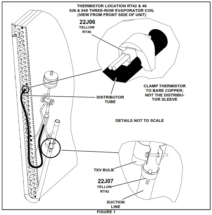
TABLE 1
036, 048
| Cat. No. | Ass’y. No. | Sensor Yellow | Figure |
| 22J06 | 623049-01 | RT46 | Figure1 |
| 22J07 | 623049-02 | RT42 | Figure1 |
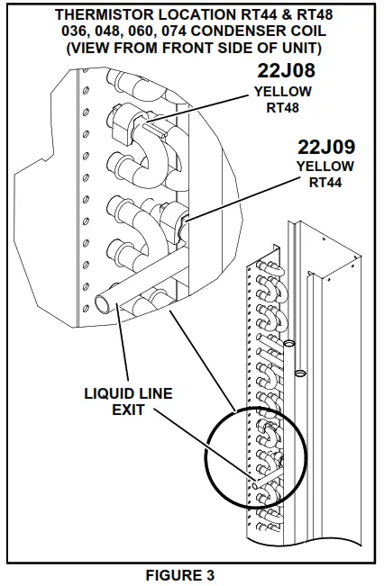
| 22J08 | 623049-03 | RT48 | Figure3 |
| 22J09 | 623049-04 | RT44 | Figure3 |
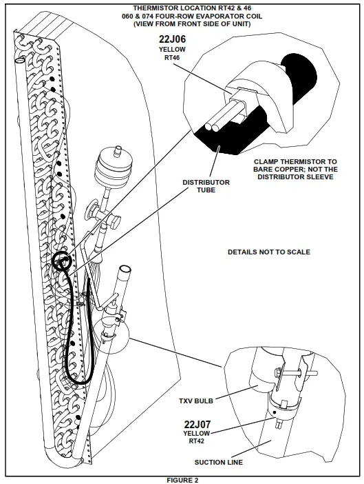
TABLE 2
060, 074
| Cat. No. | Ass’y. No. | Sensor Yellow | Figure |
| 22J06 | 623049-01 | RT46 | Figure2 |
| 22J07 | 623049-02 | RT42 | Figure2 |
| 22J08 | 623049-03 | RT48 | Figure3 |
| 22J09 | 623049-04 | RT44 | Figure3 |
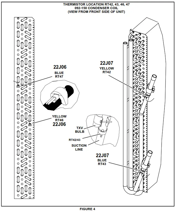
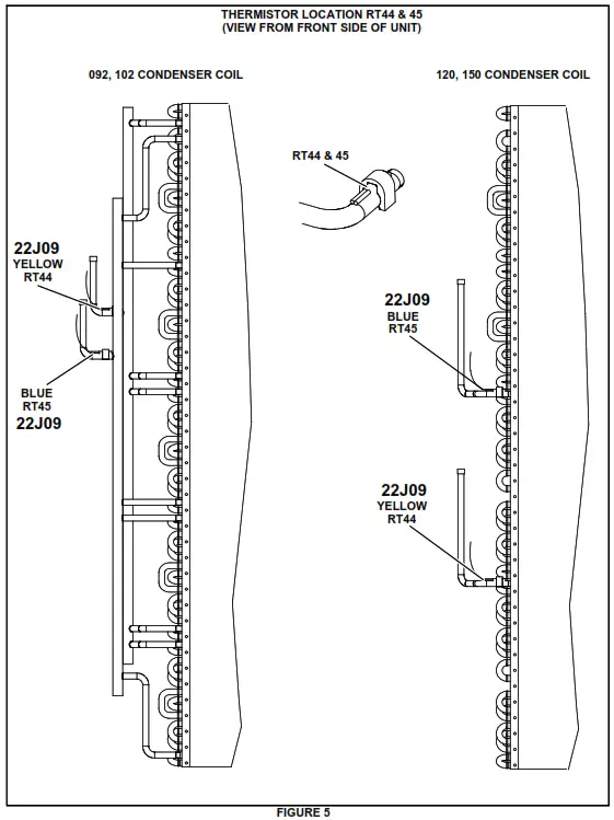
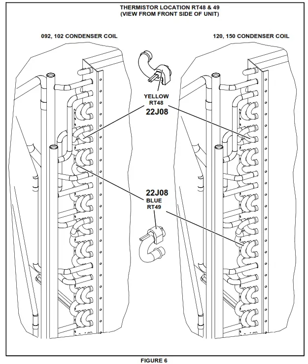
TABLE 3
092, 102, 120, 150
| Cat. No. | Ass’y. No. | Sensor Yellow, Blue | Figure |
| 22J06 | 623049-01 | RT46, 47 | Figure4 |
| 22J07 | 623049-02 | RT42, 43 | Figure4 |
| 22J08 | 623049-03 | RT48, 49 | Figure4 |
| 22J09* | 623049-04 | RT44, 45 | Figure4 |
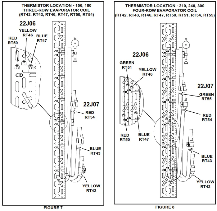
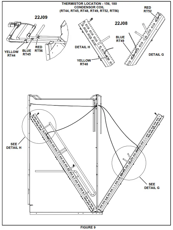
TABLE 4
156, 180
| Cat. No. | Ass’y. No. | Sensor Yel, Blue, Red | Figure |
| 22J06 | 623049-01 | RT46, 47, 50 | Figure7 |
| 22J07 | 623049-02 | RT42, 43, 54 | Figure7 |
| 22J08 | 623049-03 | RT48, 49, 52 | Figure9 |
| 22J09 | 623049-04 | RT44, 45, 56 | Figure9 |
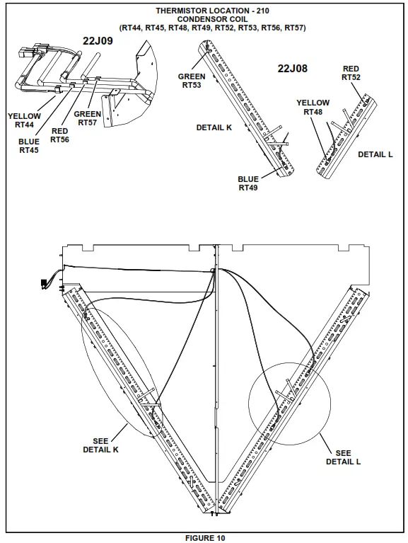
TABLE 5
210
| Cat. No. | Ass’y. No. | Sensor Yel, Blu, Red, Green | Figure |
| 22J06 | 623049-01 | RT46, 47, 50, 51 | Figure8 |
| 22J07 | 623049-02 | RT42, 43, 54, 55 | Figure8 |
| 22J08 | 623049-03 | RT48, 49, 52, 53 | Figure10 |
| 22J09 | 623049-04 | RT44, 45, 56, 57 | Figure10 |
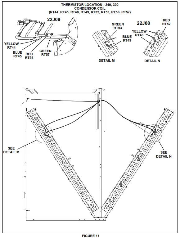
TABLE 6
240, 300
| Cat. No. | Ass’y. No. | Sensor Yel, Blu, Red, Green | Figure |
| 22J06 | 623049-01 | RT46, 47, 50, 51 | Figure8 |
| 22J07 | 623049-02 | RT42, 43, 54, 55 | Figure8 |
| 22J08 | 623049-03 | RT48, 49, 52, 53, | Figure11 |
| 22J09 | 623049-04 | RT44, 45, 56, 57 | Figure11 |
PACKAGED UNITS KITS
508172-01
4/2022
Supersedes 5/2021
©2022


