![]()
KITS COMMON TO COOLING
AND HEAT PUMP EQUIPMENT
CONTROL REPLACEMENT KIT
Installation Instructions for Outdoor Control Replacement Kit for Lennox® Communicating Modulating AC and HP Units (23U65)
RETAIN THESE INSTRUCTIONS FOR FUTURE REFERENCE
![]() WARNING
WARNING
Improper installation, adjustment, alteration, service or maintenance can cause property damage, personal injury or loss of life. Installation and service must be performed by a licensed professional HVAC installer or equivalent or service agency.![]() CAUTION
CAUTION
As with any mechanical equipment, contact with sharp sheet metal edges can result in personal injury. Take care while handling this equipment and wear gloves and protective clothing.![]() WARNING
WARNING![]() Electric Shock Hazard. Can cause injury or death. The unit must be properly grounded in accordance with national and local codes. Line voltage is present at all components when unit is not in operation on units with single-pole contactors. Disconnect all remote electric power supplies before opening the access panel. The unit may have multiple power supplies.
Electric Shock Hazard. Can cause injury or death. The unit must be properly grounded in accordance with national and local codes. Line voltage is present at all components when unit is not in operation on units with single-pole contactors. Disconnect all remote electric power supplies before opening the access panel. The unit may have multiple power supplies.
Shipping and Packing List
Package 1 of 1 contains:
1 – Communicating outdoor control (part # 104344-06)
General
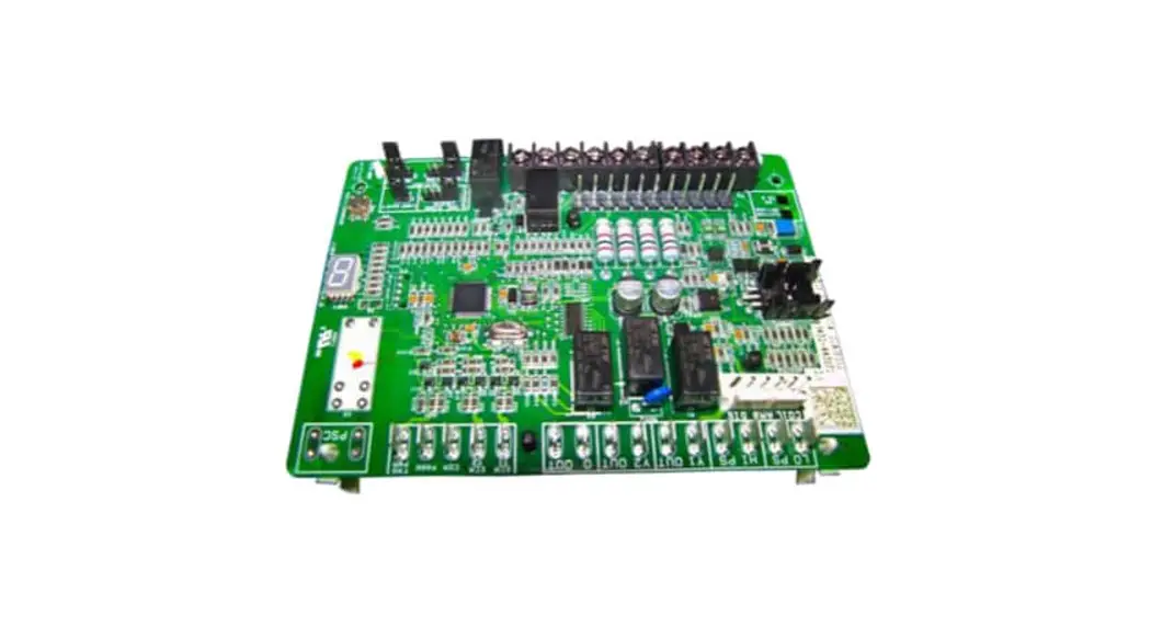
This instruction covers the removal and replacement of the communicating unit control board in outdoor units. This kit can be field-applied to models that use a modulating outdoor control.
Control Replacement
- Disconnect all power to the system (indoor and outdoor units).
- Remove the control board access panel.
- Tag location of wires attached to the existing control and use wiring diagram on access panel of outdoor unit for reference if necessary.
- Remove existing outdoor control.
- Install new outdoor control in the same location as the original outdoor control.
- Reconnect wires to the same terminals as the original outdoor control.
- Turn the main power onto the indoor unit and outdoor unit. Control should auto-commission the settings and the outdoor unit model and serial number will be transferred to the new control. On systems installed with a communicating Wi-Fi Thermostat, the thermostat will display “Compatible Device Found” Select “Yes” to copy the model and serial number into the new control. If the new control does not auto-commission, follow the procedure below to manually configure the control board.
Manual Commissioning
- Turn the main power OFF to indoor and outdoor units.
- Remove i+ and i- communication wires from the control board.
- Turn main power ON to indoor and outdoor units.
- Use the procedure outlined in Figure 1 to configure the communicating outdoor control.
NOTE – The green LED located on the outdoor control flashes when communication occurs between the outdoor control and either the thermostat or the inverter.
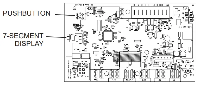
For additional information concerning terminals, seven-segment display and jumper settings, refer to either the unit installation instruction or service manual.
Configuring Unit
When installing a replacement outdoor control, the unit selection code may have to be manually assigned using the 7-segment display and pushbutton on the control. The unit code sets unit type, capacity and outdoor fan RPM.
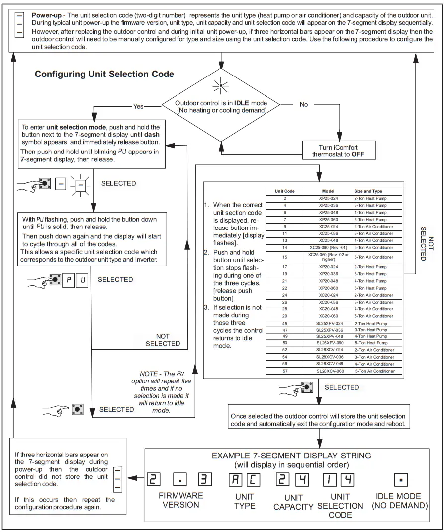
FIGURE 1. Configuring Unit Selection Code
![]()
©2022 Lennox Industries Inc.
Dallas, Texas, USA
508313-01
05/2022