LENNOX 34M72 Low Ambient Kit
INSTALLATION INSTRUCTIONS FOR LOW AMBIENT KIT
USED ON KG/KC/KH 156-300 PACKAGED ROOFTOP UNITS
Shipping and Packing List
10T62
Package 1 of 1 contains:
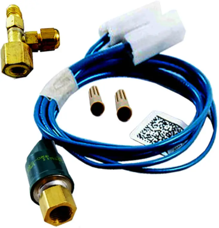
- 2- Pressure switches (S11, S84) 1- Wire harness
- 5- Wire ties
- 2- Valve depressor tees
- 6- Insertion wire ties
10T63 & 10T64 Package 1 of 1 contains:
- 3- Pressure switches (S11, S84, & S85) 1- Wire harness
- 5- Wire ties
- 3- Valve depressor tees
- 6- Insertion wire ties
10T65
Package 1 of 1 contains:
- 4- Pressure switches (S11, S84, S85, S94) 1- Wire harness
- 5- Wire ties
- 4- Valve depressor tees
- 6- Insertion wire ties
55W72
Package 1 of 1 contains:
- 3- Pressure switches (S11, S84, & S85) 3- Wire harnesses
- 5- Wire ties
- 3- Valve depressor tees
- 6- Insertion wire ties
55W73
Package 1 of 1 contains:
- 2- Pressure switches (S11, S84) 2- Wire harnesses
- 5- Wire ties
- 3- Valve depressor tees
- 6- Insertion wire ties
Application
See table 1 for usage.
TABLE 1
| Unit | Cat. # | Assembly |
| KGA/KCA 180S | 10T62 | 603364-24 |
| KGA/KCA 156H, 210S KGB/KCB 180S, 210S | 10T63 | 603364-25 |
| KGA/KCA 180H, 210H, 240S, 300S KGB/KCB 240S | 10T64 | 603364-26 |
| KGA/KCA 240H, 300H KGB/KCB 300S | 10T65 | 603364-27 |
| KG/KC 180-300* | 55W72 | LB-107318BD |
| KH 180, 240 | 55W73 | LB-107318BE |
Units built before 6/24/13.
CAUTION
As with any mechanical equipment, contact with sharp sheet metal edges can result in personal injury.
Take care while handling this equipment and wear gloves and protective clothing.
WARNING
Improper installation, adjustment, alteration, service or maintenance can cause property damage, personal injury or loss of life. Installation and service must be performed by a licensed professional HVAC installer or equivalent, service agency, or the gas supplier.
The low ambient pressure switches cycle the outdoor fan while allowing compressor operation in the cooling cycle. This intermittent fan operation results in a high evaporating temperature which allows the system to operate without icing the evaporator coil and losing capacity. This kit is designed for use in ambient temperatures no lower than 0°F (-17.8°C) unless otherwise noted in the Engineering Handbook.
Install a belly-band style crankcase heater on compressors which don’t have one.
Pressure Switch Installation
- Disconnect power to unit.
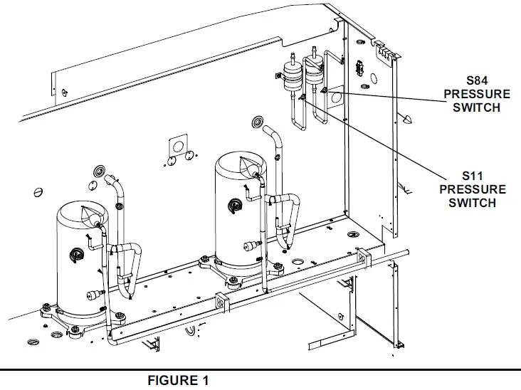
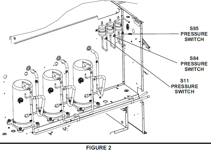
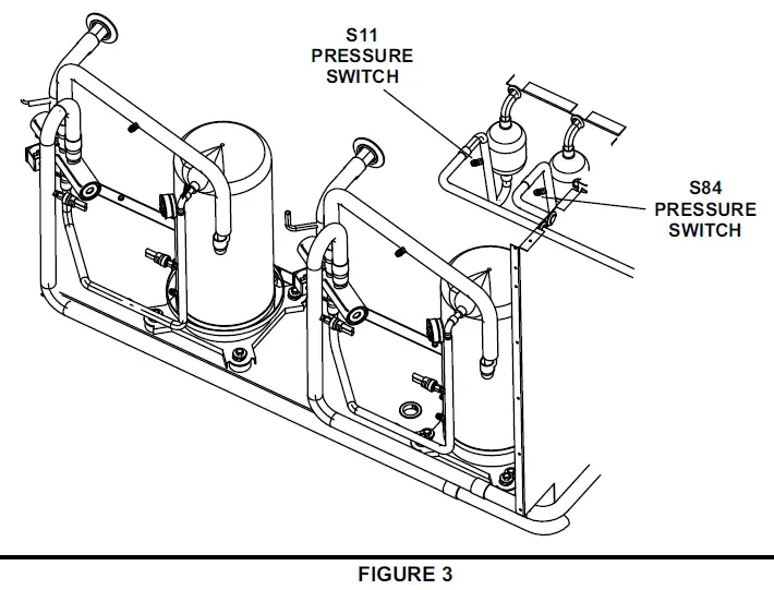
- Refer to table 2 for figure number showing switch location. Open appropriate unit panel.
- Install teevalve depressors on liquid line pressure taps. Install the pressure switches on the teevalve depressors.
- Check system for leaks.
TABLE 2
| Unit | Switch Location |
| KGA/KCA 180S | Figure 1 |
| KGA/KCA 210S, 240S, 300S, 156H, 180H, 210H KGB/KCB 180S, 210S, 240S | Figure 2 |
| KH 180, 240 | Figure 3 |
| KGA/KCA 240H, 300H KGB/KCB 300S | Figure 4 |
PRESSURE SWITCH LOCATION – KGA/KCA 180S UNITS
PRESSURE SWITCH LOCATION –
KGA/KCA 156H, 180H, 210S/H, 240S, 300S AND KGB/KCB 180S, 210S, 240S UNITS
PRESSURE SWITCH LOCATION – KH 180 & 240 UNITS
PRESSURE SWITCH LOCATION –
KGA/KCA 240H & 300H AND KGB/KCB 300S UNITS
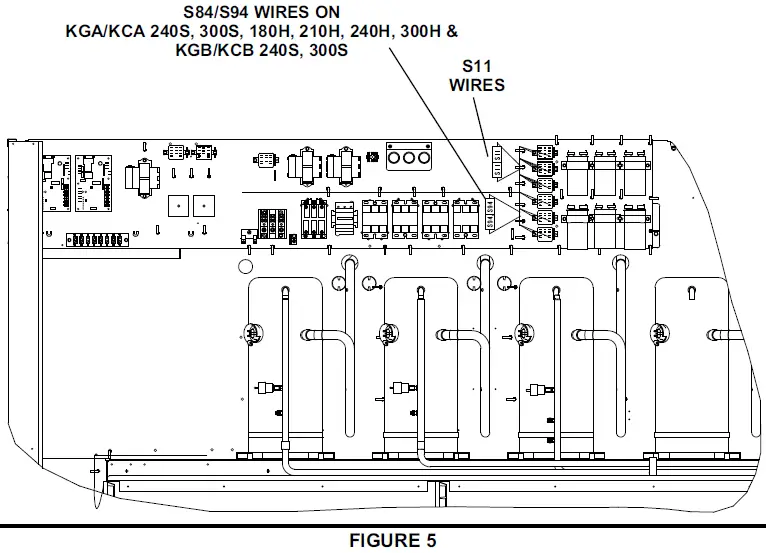
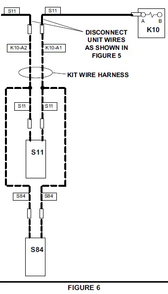
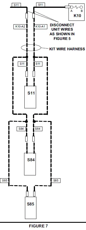
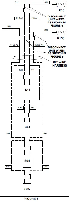
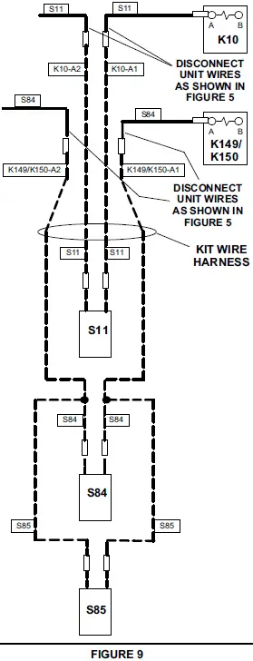
Pressure Switch Wiring – KG/KC Units Built After 6/24/2013
- Disconnect unit wires marked S11 and S84/S94 as shown in figure 5.
- Wire pressure switches. Refer to table 3 For appropriate wiring diagrams.
- Bundle wiring and secure away from unit components.
- Close all unit panels and restore power to unit.
TABLE 3
| Unit | Wiring |
| KGA/KCA 180S | Figure 6 |
| KGA/KCA 210, 156H KGB/KCB 180S, 210S | Figure 7 |
| KG/KC 240H, 300H | Figure 8 |
| KG/KC 240S, 300S, 180H & 210H | Figure 9 |
DISCONNECT S11 AND S84/S94 WIRES – UNITS BUILT AFTER 6/24/2018
WIRING – KGA/KCA 180S UNITS
WIRING – KGA/KCA 210S, 156H AND KGB/KCB 180S, 210S UNITS
WIRING – KGA/KCA 240H & 300H AND KGB/KCB300S UNITS
WIRING – KGA/KCA 240S, 300S, 180H & 210H AND KGB/KCB 240S UNITS
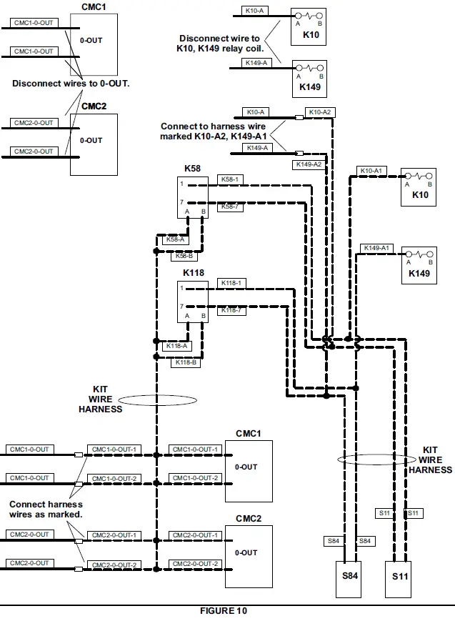
Pressure Switch Wiring – KH Units
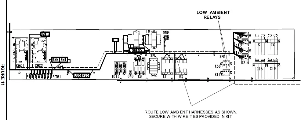
- Use two harnesses, provided in kit, to wire pressure switches. See figure 10. Route harnesses as shown in figure 11.
- Bundle wiring and secure away from unit components.
WIRING – KH 180 & 240 UNITS
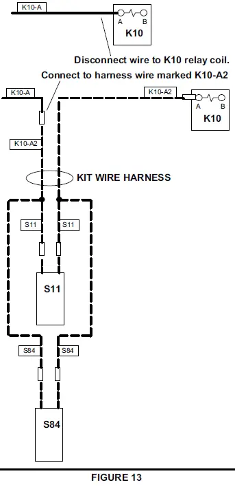
Pressure Switch Wiring KG/KC 180-300
Units Built Before 6/24/2013
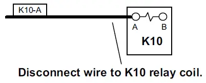
- KG/KC 180 & 210 Units – Disconnect unit wire to K10-A.
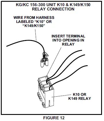
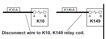
KG/KC 240 & 300 Units – Disconnect unit wire to K10-A and K149-A. - Wire pressure switches. Refer to table 5 for appropriate wiring diagram. See figure 12 to connect harness wire to K10 or K10 and K149.
NOTE – Three different wiring harnesses are provided in this kit. Use wiring harness which has stamps as shown in appropriate figure; tape back unused wires. Discard unused harnesses.
Bundle wiring and secure away from unit components.
TABLE 5
| Unit | Wiring Figure |
| KG/KC 180 | Figure 13 |
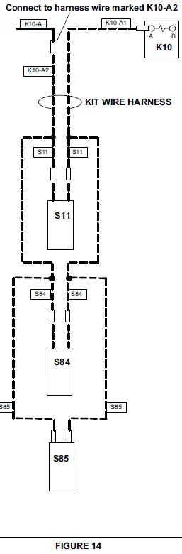
| KG/KC 210 | Figure 14 |
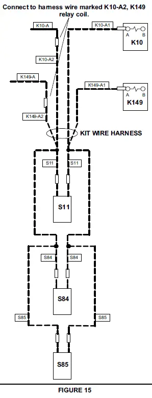
| KG/KC 240 & 300 | Figure 15 |
KG/KC 156-300 UNIT K10 & K149/K150
RELAY CONNECTION
WIRING – KG/KC 180 UNITS
WIRING – KG/KC 210 UNITS
Connect to harness wire marked K10-A2
WIRING – KG/KC 240 & 300 UNITS
Operation
Outdoor fans will be energized when the liquid pressure rises to 450 psig (3103kPa) and de-energize when liquid pressure drops to 240 psig (1655kPa).
KG/KC 180S, 210S & 156H –
Outdoor fans cycle together (all switches must be open).
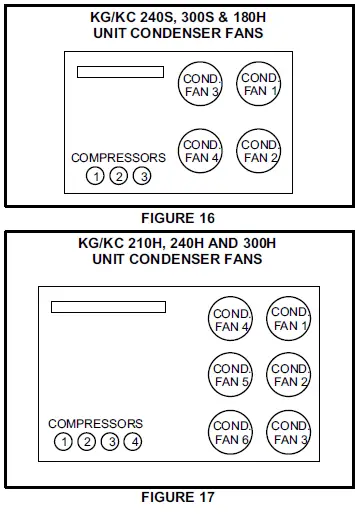
KG/KC 240S, 300S & 180H, KGA/KCA300S –
Outdoor fans 1 & 2 cycle together; outdoor fans 3 & 4 cycle together. See figure 16.
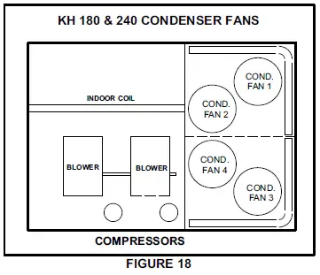
KGA/KCA 210H, 240H & 300H and KGB/KCB300S –
Outdoor fans 1, 2 & 3 cycle together; outdoor fans 4, 5 & 6 cycle together. See figure 17.
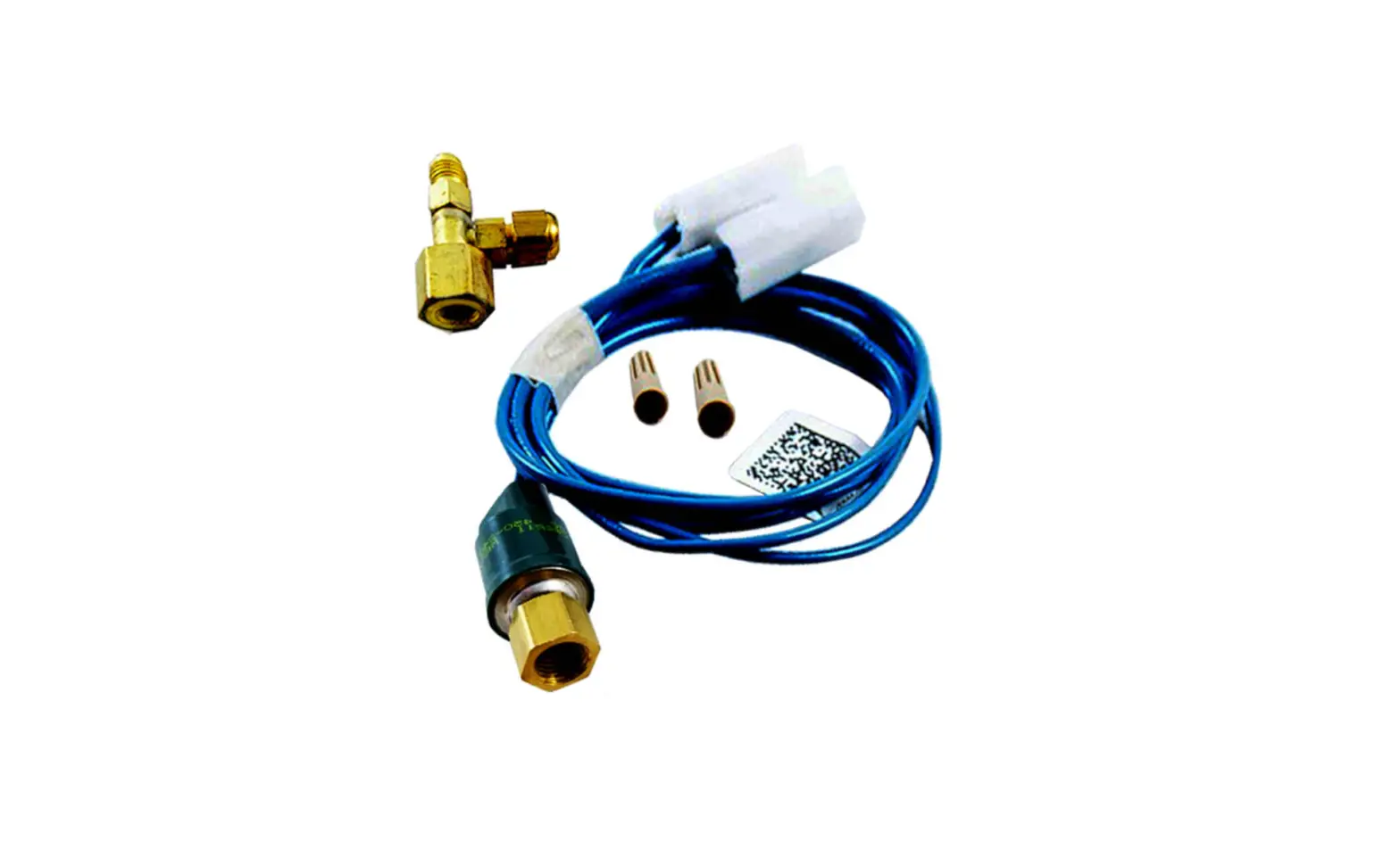
KH 180 & 240 –
Outdoor fans 1 & 2 cycle together; outdoor fans 3 & 4 cycle together. See figure 18.
When heat pump units operate in heating mode, K58 bypasses S11 and S84 pressure switches to keep fans operating regardless of liquid pressure.