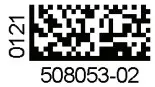
![]() 508053-02 Gas Units Kits
508053-02 Gas Units Kits
Instructions
 WARNING
Improper installation, adjustment, alteration, service, or maintenance can cause property damage, personal injury, or loss of life. Installation and service must be performed by a licensed professional HVAC installer or equivalent, service agency, or gas supplier.
CAUTION
As with any mechanical equipment, contact with sharp sheet metal edges can result in personal injury. Take care while handling this equipment and wear gloves and protective clothing.
Shipping and Packing List
Package 1 of 1 contains:
- Discharge air temperature sensor
Application
Use discharge air temperature sensor kit 20A60 to measure temperature rise in the heating mode and temperature drop in the cooling mode.
Installation
- Shut off all power to the unit.
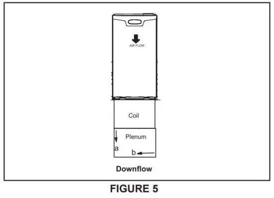
New installation - See tables 1 through 4 and figures 2 through 5 for the location of the discharge air sensor.
- Drill a 3/8 inch diameter hole in the supply duct based on the specified location.
- Center the discharge air temperature sensor in the middle of the hole and use two fields provided screws to secure in place
NOTE – The orientation of the sensor mounting flange is not critical and can be oriented to whatever position is needed to prevent interference with the evaporator coil, air duct, etc. - Connect field supplied wiring to the discharge air temperature sensor terminals on the integrated control board. See figure 1.
Replacement - Remove the current discharge air temperature sensor. Set scews aside. Compare to the provided replacement sensor. If not the same type then new locations holes must be drilled and current holes MUST be sealed. See steps 2 through 5. If the sensor is the same type continue to step 7.
- Install the new discharge air temperature sensor and secure using the same screws from step 6.
NOTE- Insert the sensor FULLY into the plenum. - Connect field supplied wiring to the discharge air temperature sensor terminals on the integrated control board. See figure 1.
- Return power to the unit.
NOTE – If the system does not include an evaporation coil, the sensor should be installed according to the following:
- Place the sensor as far away from the direct heat source in the main plenum as possible. A minimum of 19” is recommended but up to 36” is preferred.
- Offset the sensor 1/4 of the width of the plenum from the left edge of the plenum in up-flow, top edge of the plenum in the horizontal right, and bottom of the plenum in the horizontal left. For example, if the plenum is 16” wide then offset the sensor 4” from the edge. The sensor should report a temperature within this range of the furnace. If the readings from the sensor appear to be below the rising range of the furnace, move The sensor in 1” increments towards the center of the plenum until the sensed temperature is within the rising range of the furnace. If the sensor reading appears to be too high, move the sensor in 1” increments towards the edge of the plenum until the sensed temperature is within the rising range of the furnace.
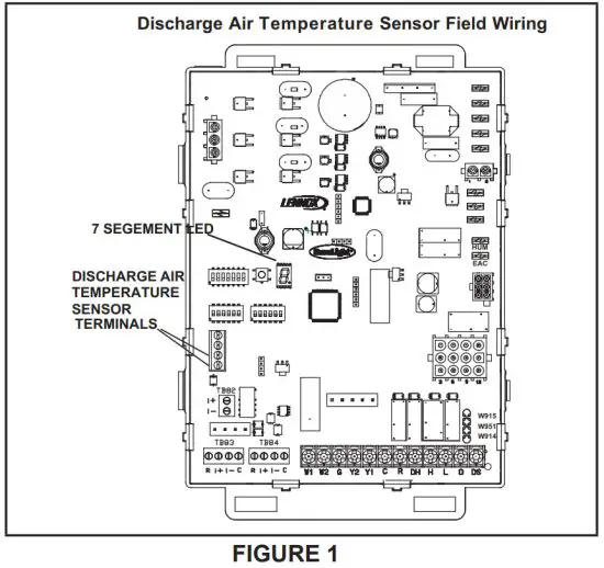
TABLE 1
Discharge Air Temperature Sensor Location Upflow
| SLP99UH Model | “a” | “b” | Mounting Surface |
| 070XV36B | 2″ | Center | Plenum Duct |
| 090XV36C | 3″ | Center | |
| 090XV48C | 2″ | 7″ from right | |
| 090XV60C | 3″ | 4″ from left | |
| 110XV60C | 2″ | 8″ from right | |
| 135XV60D | 2″ | 7″ from left |
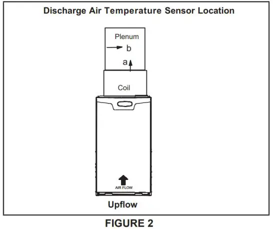
TABLE 2
Discharge Air Temperature Sensor Location Horizontal Left
| SLP99UH Model | ” a” | “b” | Mounting Surface |
| 070XV36B | 5″ | Center | Plenum Duct |
| 090XV36C | 3″ | 4″ from bottom | |
| 090XV48C | 2″ | 7″ from bottom | |
| 090XV60C | 4″ | 3″ from bottom | |
| 110XV60C | 3″ | 8″ from bottom | |
| 135XV60D | 2″ | 7″ from bottom |
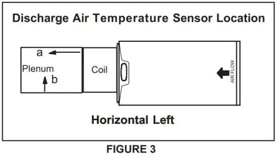
TABLE 3
Discharge Air Temperature Sensor Location Horizontal Right
| SLP99UH Model | “a„ | “b” | Mounting Surface |
| 070XV36B | 5″ | Center | Plenum Duct |
| 090XV36C | 2″ | 8″ from bottom | |
| 090XV48C | 3″ | Center | |
| 090XV60C | 3″ | 7″ from top | |
| 110XV60C | 3″ | Center | |
| 135XV60D | 2″ | 7″ from top |
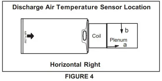
TABLE 4
Discharge Air Temperature Sensor Location Downflow
| SLP99DF Model | “a” | “b” | ‘Mounting Surface |
| 070XV36B | 6″ | Center | Plenum Duct |
| 090XV36C | |||
| 090XV48C | |||
| 090XV60C | |||
| 110XV60C |
- If unable to mount at the specified location, the sensor can be mounted in the coil cabinet 1” from the bottom and 5” from the right side. Care must be exercised to avoid hitting the coil/drain pan while drilling through the cabinet.