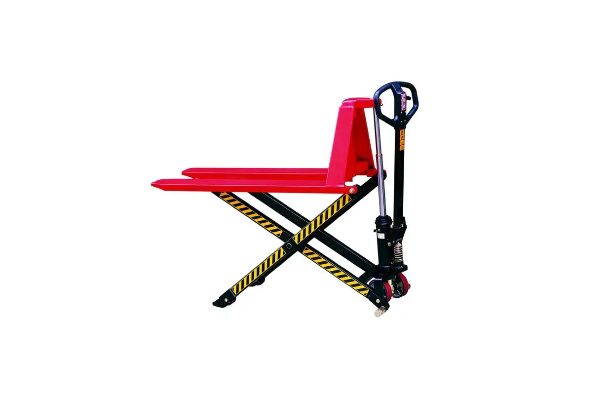
GLOBAL INDUSTRIAL JL5210 High Lift Pallet Truck Instruction Manual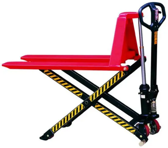
Specifications
| Model | JL5210 | JL6810 | JL5215 | JL6815 |
| Rated Capacity | 1000 kgs | 1500 kgs | ||
| Max. Lifting Height | 800 mm | |||
| Min. Fork Height | 85 ±2 mm | |||
| Fork Length | 1140 mm | 1100mm | ||
| Fork Overall Width | 520mm | 680mm | 520mm | 680mm |
| N.W. | 92kgs | 96kgs | 104 kgs | 109kgs |
Safety Instructions
- The truck shall be used in accordance with the instructions manual.
- Do not place hands or feet under the fork at any time.
- Do not work on sloped or inclined surfaces, only level ground.
- Quick lifting is prohibited for loads of more than 150 kgs. Any manipulation of the pressure relief valve is strictly prohibited.
Assembly, maintenance, and adjustments should be done by a trained professional. These people must be familiar with all safety regulations of European and national where the item is in use relating to the operation and maintenance of pedestrian controlled industrial trucks. - Load should be put on the fork center. Off-center loading is strictly prohibited.
- The truck shall not be used to transport persons.
- It is recommended to the driver to wear steel/composite toe shoes.
- No modifications shall be carried out which adversely affect the compliance of the truck with prEN 1757-4.
Installation and Adjustment
- 1. Screw (part No.158)
To prevent oil leaking from oil tank during transportation, Air
Screw (part No.158) is replaced with Oil-sealing Screw in the
factory. But it has to be replaced back when you put this truck
in use.
How to change: Screw out Oil-sealing Screw, then screw in Air
Screw, thus keep oil tank always connecting with atmosphere. - Handle
During transportation, the handle is disassembled from the truck and packed separately. It has to be assembled back and adjusted properly and carefully before use.- A. Handle installation:
- Take 3 M10 socket head screws (No.185) and spring washers (No.186) & Hex Wrench from spare parts bag. Select handle to match the truck with the same fitting numbers.
- Assemble the handle on the Handle Base (No.181) with 3 M10 screws and Washers tightly.
Put the chain’s Eye Bolt (No.110) in the slot at the front end of Pendulum Arm (No.112).
- B. Handle adjustment
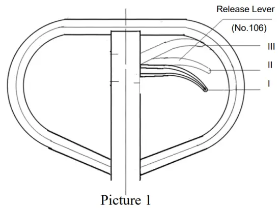
- There are 3 different positions with different functions for the Release Lever (Part No.106)
Position I: Lifting for fork.
Position II: Neutral for fork.
Position III: Descending for fork.
- Test different functions of the Release Lever
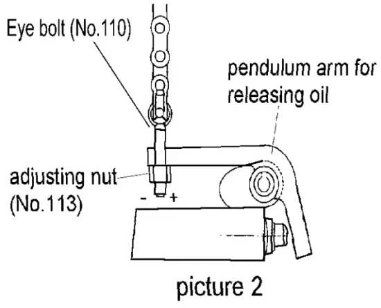
Problems Turning direction of Lock Nut Fork will not lift - (counter-clockwise)
Fork will not lower + (clockwise) - If it does not function properly, then adjust Lock Nut (No.113) by following process. See picture 2.

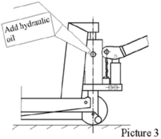
- When to add oil
See Picture 3.
If the fork can’t be pumped up to its rated highest position, you may have to add hydraulic oil into the oil tank. The hydraulic fluid to be used must have a viscosity of ISO VG22 or equivalence.
Mixing of different fluids is prohibited!
- There are 3 different positions with different functions for the Release Lever (Part No.106)
- A. Handle installation:
Trouble Shooting Guide
| Items | Symptom | Possible Cause | Solutions |
| 1 | Fork cannot be pumped up. |
|
|
| 2 | Fork can’t be released down. | Fork blocked. 1. Pendulum arm nut not adjusted properly. |
|
| 3 | Fork can’t be pumped up to rated highest position. | Hydraulic oil depleted | Add hydraulic oil (See picture 3.) |
| 4 | Neutral has no difference between position I and position II of release lever | Pendulum arm nut is not adjusted properly. | Adjust pendulum arm nut (See picture 2) |
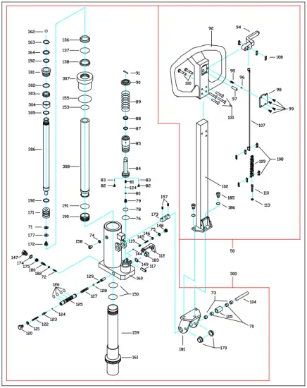
Parts List
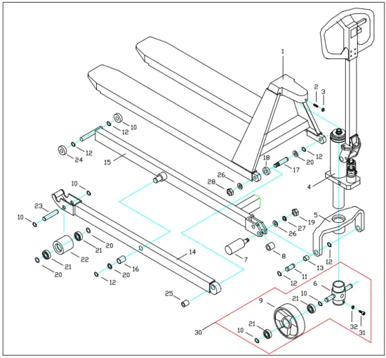
| Item No. | Description | Q’ty |
| 1 | Fork | 1 |
| 2 | Screw | 1 |
| 3 | Nut | 1 |
| 4 | Power Unit | 1 |
| 5 | Hold Yoke | 1 |
| 6 | Wheel Yoke | 1 |
| 7 | Centrifugal Axle | 2 |
| 8 | Spacer | 2 |
| 9 | Steering Wheel | 2 |
| 10 | Snap Ring | 8 |
| 11 | Pin | 2 |
| 12 | Snap Ring | 12 |
| 13 | Bushing | 2 |
| 14 | Leg | 2 |
| 15 | Leg | 1 |
| 16 | Bushing | 2 |
| 17 | Pin | 2 |
| 18 | Washer | 2 |
| 19 | Nut | 2 |
| 20 | Washer | 8 |
| 21 | Ball Bearing | 8 |
| 22 | Front Wheel | 2 |
| 23 | Wheel Axle | 2 |
| 24 | Roller | 4 |
| 25 | Bushing | 2 |
| 26 | Washer | 4 |
| 27 | Spring Washer | 2 |
| 28 | Lock Nut | 2 |
| 31 | Screw | 1 |
| 32 | Nut | 1 |
| 30 | Steering Wheel Assembly (incls.6,9,10,21,31,32) | 1 |
| Item No. | Description | Q’ty |
| 70 | Bushing | 2 |
| 71 | Washer | 1 |
| 72 | Spring | 1 |
| 73 | Spacer | 2 |
| 74 | Washer | 1 |
| 75 | Gasket | 1 |
| 76 | O-Ring | 1 |
| 78 | O-Ring | 1 |
| 79 | Screw | 1 |
| 80 | O-Ring | 1 |
| 81 | Spring | 1 |
| 82 | Spring | 2 |
| 83 | Ball | 2 |
| 84 | Plunger | 1 |
| 85 | Pump | 1 |
| 87 | Y-Ring | 1 |
| 88 | Scraper Ring | 1 |
| 89 | Spring | 1 |
| 90 | Washer | 1 |
| 91 | Pin | 1 |
| 92 | Handle | 1 |
| 94 | Release Lever | 1 |
| 95 | Spring | 1 |
| 96 | Ball | 1 |
| 97 | Pin | 1 |
| 98 | Cover | 1 |
| 99 | Screw | 4 |
| 100 | Pin | 6 |
| 102 | Handle Tube | 1 |
| 104 | Pin | 1 |
| 105 | Roller | 1 |
| 107 | Release Rod | 1 |
| 108 | Chain Connector | 3 |
| 109 | Chain | 1 |
| 110 | Eye Bolt | 1 |
| 112 | Pendulum Arm | 1 |
| 113 | Pendulum Arm Nut | 1 |
| 117 | Pin | 1 |
| 119 | Seat | 1 |
| 120 | Screw | 1 |
| 121 | Gasket | 1 |
| 122 | Spring | 1 |
| 123 | Release Valve | 1 |
| 124 | Ball | 2 |
| 125 | Valve Insert | 1 |
| 126 | O-Ring | 4 |
| 127 | Spring | 1 |
| 128* | O-Ring | 1 |
| 129 | Release Indicator | 1 |
| 136 | Scraper Ring | 1 |
| 137 | O-Ring | 1 |
| 138 | Y-Ring | 1 |
| 144 | Ball | 1 |
| 145 | Spring | 1 |
| 146 | Adjusting Screw | 1 |
| 147 | Sealing Screw | 1 |
| 148 | Screw | 1 |
| 149 | Snap Ring | 1 |
| 150 | O-Ring | 2 |
| 153 | O-Ring | 1 |
| 155 | O-Ring | 1 |
| 157 | Screw | 2 |
| 158 | Air Screw | 1 |
| 159 | Cylinder | 1 |
| 160 | Pump Housing | 1 |
| 161 | Thrust Bearing | 1 |
| 162 | Ball | 1 |
| 163 | Snap Ring | 1 |
| 164 | Washer | 1 |
| 170 | Bushing | 2 |
| 171 | Piston | 1 |
| 172 | Screw | 1 |
| 173 | Axle | 1 |
| 174 | Gasket | 1 |
| 175 | Lock Screw | 1 |
| 177 | Washer | 1 |
| 180 | Adjusting Screw | 1 |
| 181 | Handle Base | 1 |
| 182 | Adjusting Washer | 1 |
| 183 | Rubber Sleeve | 1 |
| 185 | Socket Head Screw | 3 |
| 186 | Spring Washer | 3 |
| 190 | Copper Piston | 1 |
| 191 | Snap Ring | 1 |
| 192 | Snap Ring | 2 |
| 301 | Bushing | 1 |
| 302 | Back-Up Ring | 1 |
| 303 | Y-Ring | 1 |
| 304 | Bushing | 1 |
| 305 | Snap Ring | 1 |
| 306 | Piston Rod | 1 |
| 307 | Cylinder Head | 1 |
| 308 | Cylinder | 1 |
| 300 | Pump Unit | 1 |
| 50 | Handle Assembly | 1 |
| Remark: Parts with “*” mark are supplied together with the High Lifter and packed in the poly bags. | ||