![]()
User’s manual
Customer Service
US : 1-800-645-2986
Instruction Manual
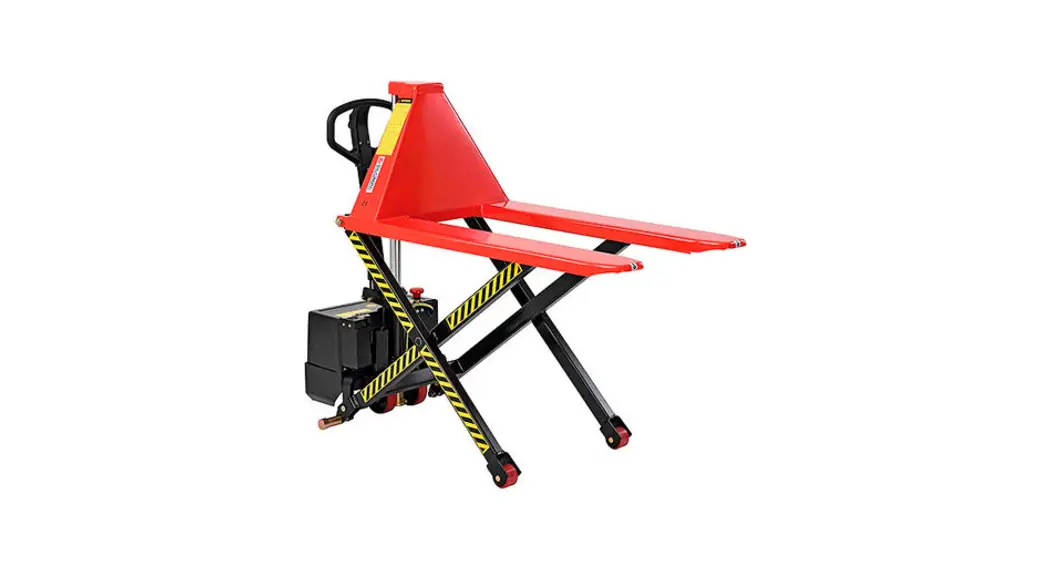
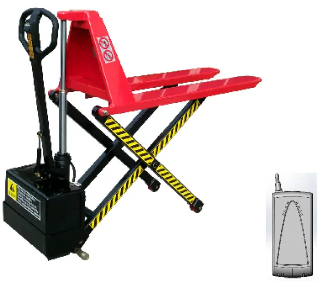
ELECTRIC HIGH LIFT TRUCK
Note: Owner/Operator must read and understand this instruction manual before using the electric high lift truck.
Contents hide
Specifications
| Model | JE5210B | JE6810B | JE5215B | JE6815B | |||
| Rated Capacity | (kg) | 1000 | 1500 | ||||
| Max Height Capacity | (kg) | ??? | 1000 | ||||
| Max. Lifting Height | (mm) | 800 | |||||
| Min. Fork Height | (mm) | 85 | |||||
| Fork Length | (mm) | 1140 | 1100 | ||||
| Fork Overall Width | (mm) | 520 | 680 | 520 | 680 | ||
| Dia. of Front Wheel | (mm) | ∅75 X 50 | |||||
| Dia. of Rear Wheel | (mm) | ∅150 X 40 | |||||
| Motor Working Voltage | 12V | ||||||
| Battery | 60Ah/12V | ||||||
| Charger | 6A/12V | ||||||
| Net Weight | (kg) | 134 | 138 | 145 | 150 | ||
Assembly and Adjustment
- Carefully remove pallet truck from packaging.
- Insert handle (102) into pump housing (160); lock it with pin (108) and two screws (109). Swing the handle up and down to see if it moves freely. Finally put on spring (105).
- Open the electrical control case by removing the cover (255). Insert switch wire and plug (184) hanging down from handle (102) into socket (221) in the case. Insert one fuse of 5 Amp (277) into two sockets of F2.
- Check the electrical device and elements in the case to see if they are loose, drop down or break.
- Check oil pipes in the hydraulic system to see if they are screwed tightly.
Remove oil cap (217) to see if oil level is sufficient (at least ¾ full) - Fully raise and lower the fork using the Up-Down switch (197) to check that electrical and hydraulic systems are working properly. Repeat 3 to 4 times to make absolutely sure that all systems are in order and to remove possible air bubbles in hydraulic fluid.
- Close the case with cover (255) and screw it tightly with screw (256).
Operation
- JE series are designed for working on flat, level ground.
- Handle (102) is used for pulling and steering.
- When the fork is lifted to its highest position, JE series should not be moved.
- Up-button moves the fork up, Down-button moves the fork down. The fork can stop at any position and won’t slide down.
- A safety valve is built into the hydraulic system to prevent overloading. When lifting a load over 1000 kg, the piston rod (406) cannot extend and lift the load. The outer hydraulic cylinder (413) can fully extend and lift loads up to the model’s full rated capacity.
NOTE: This means loads over 1000 kg cannot be lifted to maximum height. - Cease operation when the battery indicator is at or below the red line. Operating the JE series in this state can cause premature wear and damage to battery (254). Plug recharger (271) into a compatible power socket, then connect the recharger to the electrical control case Socket (225). The battery will begin to recharge. For detailed
specifications please refer to the nameplate on the recharger.
Battery Use & Maintenance Instructions
The battery is an easily-worn part, and the function could be weakened
by various factors. Proper operation and maintenance are key to a
prolonged service life.
- Status of storage battery
1.1 Battery is fully charged at or slightly above 12.5 volts.
1.2 If battery is between 11.5-12.5V, battery is not fully charged and needs charging;
1.3 If battery is below 11.5V, open the electric box cover (255), and check the indicator of the state of charge on the battery cover. If the indicator is black, please check the charger and power supply, if both are working, continue recharging; if indicator is white, replace the battery. - When JE series is lifting with maximum rated load, the continuous working time of the motor should not exceed 40 seconds, and there should be a time interval of 3-5 minutes before lifting the next load.
- Charging instructions Recharge when voltmeter is red.
Precautions
- Read the manual carefully before Finish every procedure as required in the manual.
- Lifting the fork to its full range 1 to 2 times before use to release the air in the hydraulic system.
- JE series is not designed to lift any person or individual. The JE series is also not designed to work on sloped or inclined surfaces.
- Do not place hands or feet under fork or on piston rod (406) and mid-cylinder (413).
- Place the load on the center of the fork. Eccentric loading is strictly
- The safety valve in the pump station will be automatically open when it is overloaded. Under such circumstance, DO NOT push the up-button, or the station may be
- To replace or fill hydraulic oil, the forks should be lowered to the lowest Make sure the new oil is clean. The oil condensation point should be 5 -20°C. The motion viscosity should be 20-30 cst (centistokes).
Common Problems and Maintenance
| No. | Symptom | Cause | Remedy |
| 1 | Fork does not lift up when pushing up- button |
|
|
| 2 | Fork does not descend when pushing down- button |
|
|
| 3 | Fork does not lift to highest position |
|
|
| 4 | Motor does not work |
|
|
| 5 | Battery not recharging |
|
|
| 6 | Oil leakage from Piston Rod & Mid-cylinder |
|
|
| 7 | Unsteady in highest position |
|
|
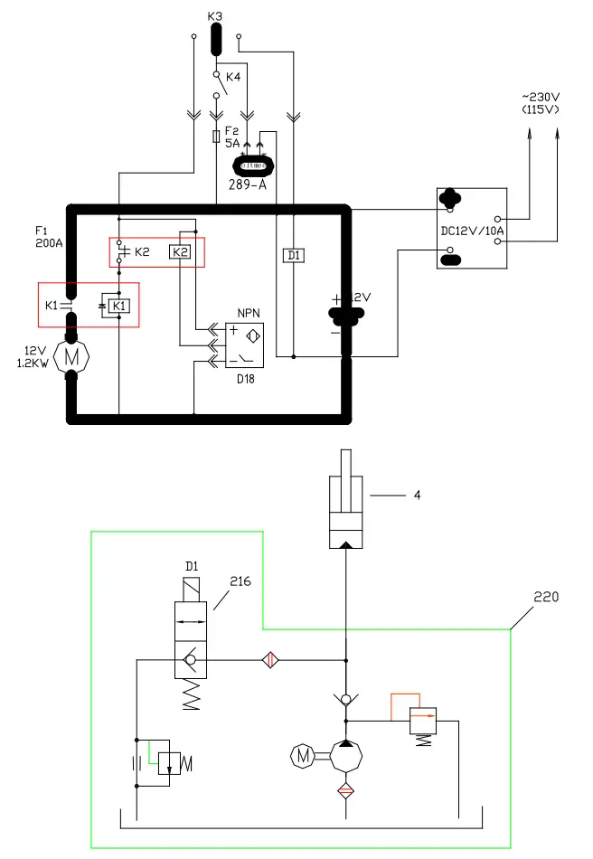
HYDRAULIC CIRCUIT / ELECTRIC WIRING
DIAGRAM
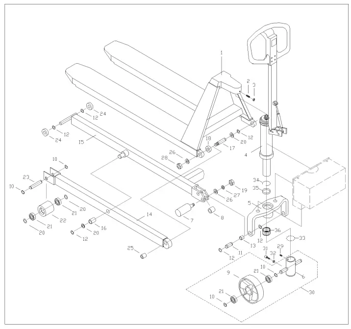
EXPOLDED FIGURE & PARTS LIST
| Item No. | Description | Q’ty |
| 1 | Fork | 1 |
| 2 | Screw | 1 |
| 3 | Nut | 1 |
| 4 | Power Unit | 1 |
| 5 | Hold Yoke | 1 |
| 6 | Wheel Yoke | 1 |
| 7 | Centrifugal Axle | 2 |
| 8 | Spacer | 2 |
| 9 | Wheel | 2 |
| 10 | Snap Ring | 8 |
| 11 | Pin | 2 |
| 12 | Snap Ring | 12 |
| 13 | Bush | 2 |
| 14 | Leg | 2 |
| 15 | Leg | 1 |
| 16 | Bush | 2 |
| 17 | Pin | 2 |
| 18 | Washer | 2 |
| 19 | Nut | 2 |
| 20 | Washer | 8 |
| 21 | Ball bearing | 8 |
| 22 | Front wheel | 2 |
| 23 | Wheel axle | 2 |
| 24 | Roller | 4 |
| 25 | Bush | 2 |
| 26 | Washer | 4 |
| 27 | Spring washer | 2 |
| 28 | Lock Nut | 2 |
| 29 | Screw | 1 |
| 30 | Wheel assembly (items 6,9,10,21) | 1 |
| 31 | Screw | 1 |
| 32 | Nut | 1 |
| 33 | Ball | 51 |
| 34 | Snap ring | 1 |
| 35 | Bush | 1 |
| 36 | quill bearing | 1 |
EXPOLDED FIGURE & PARTS LIST
OF ELECTRIC CONTROL ASSEMBLY
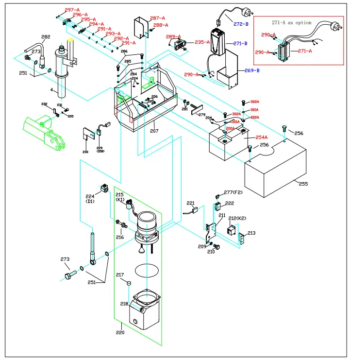
| Item No. | Description | Q’ty |
| 4 | Power Unit | 1 |
| 202A | connecting terminal(+) | 1 |
| 202A | connecting terminal (-) | 1 |
| 204 | Terminal | 2 |
| 205 | Washer | 3 |
| 206 | Screw | 2 |
| 207 | Electric Control Case | 1 |
| 209 | Spring Washer | 1 |
| 210 | Screw | 1 |
| 211 | Fuse Base | 1 |
| 212 | Relay | 1 |
| 213 | Relay Base | 1 |
| 215 | Relay | 1 |
| 216 | Control Valve | 1 |
| 217 | Cap | 1 |
| 218 | Oil Tank | 1 |
| 220 | Pump Station Assembly | 1 |
| 221 | Switch Socket | 1 |
| 222 | Fuse Box | 1 |
| 224 | Magnet | 1 |
| 225 | Recharger Socket | 1 |
| 229 | Switch | 1 |
| 230 | Switch Base | 1 |
| 231 | Screw | 1 |
| 232 | Moving Plate | 1 |
| 233 | Cover | 1 |
| 234 | Switch | 1 |
| 235 | Volt Meter | 1 |
| 251 | Washer | 4 |
| 254 | Battery ,12V/60Ah | 1 |
| 255 | Cover | 1 |
| 256 | Screw | 2 |
| 269-B | Recharger Box | 1 |
| 271-A | Recharger ( option) | 1 |
| 271-B | Recharger | |
| 272-B | power cord | 1 |
| 273 | Screw | 2 |
| 277 | Fuse,5A | 1 |
| 279 | Fixing Screw for Battery | 1 |
| 281 | Nut | 2 |
| 282 | High Pressure Oil Pipe | 1 |
| 284 | Washer | 2 |
| 285 | Washer | 2 |
| 286 | Screw | 2 |
| 287-A | Box | 1 |
| 288-A | Screw | 2 |
| 289-A | Screw | 2 |
| 290-A | Screw | 2 |
| 291-A | Nut | 4 |
| 292-A | Spring Washer | 2 |
| 293-A | Washer | 2 |
| 294-A | Fuse(150A) | 1 |
| 295-A | Screw | 2 |
| 296-A | Fuse Base | 1 |
| 297-A | Nut | 2 |
| 235-A | Voltage Meter | 1 |
| 301A | Washer | 2 |
| 302A | Screw | 2 |
| 303A | 0-ring | 1 |
EXPOLDED FIGURE & PARTS LIST
OF PUMP ASSEMBLY
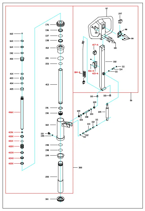
| Item No. | Description | Remark |
| 97 | Handle | 1 |
| 98 | Cover | 1 |
| 99 | Screw | 4 |
| 100 | Pin | 6 |
| 101 | Spacer | 2 |
| 102 | Handle tube | 1 |
| 103 | Washer | 2 |
| 105 | Tension spring | 1 |
| 108 | Pin | 1 |
| 109 | Screw | 2 |
| 110 | Adjusting screw | 1 |
| 111 | Snap ring | 4 |
| 112 | Sleeve | 2 |
| 113 | Pin | 1 |
| 114 | Pin | 1 |
| 136 | Scraper ring | 1 |
| 137 | 0-ring | 1 |
| 138 | 11-ring | 1 |
| 153 | 0-ring | 1 |
| 160 | Pump housing | 1 |
| 161 | Thrust bearing | 1 |
| 162 | Ball | 1 |
| 163 | Snap ring | 1 |
| 164 | Washer | 1 |
| 176 | Rubber sleeve | 1 |
| 184-A | Switch wire & plug | |
| 190 | Copper piston | 1 |
| 191 | Snap ring | 1 |
| 192 | Snap ring | 1 |
| 195 | Washer | 1 |
| 197 | Up-down switch | 1 |
| 198 | 0-ring | 2 |
| 199 | Bushing | 1 |
| 200 | Cylinder | 1 |
| 201 | Back-Up ring | 1 |
| 400 | Bronze Bushing | 1 |
| 403 | Bushing | 1 |
| 404 | Snap Ring | 1 |
| 405 | Bushing | 1 |
| 406X | Piston Rod | 1 |
| 412 | Cylinder Head | 1 |
| 413 | Cylinder | 1 |
| 414 | Snap Ring | 1 |
| 415-A | Switch housing | |
| 416-A | Screw | |
| 417-A | switch | 1 |
| 419X | Snap ring | 1 |
| 420X | Bushing | 2 |
| 421X | 0-Ring | 1 |
| 422X | Piston | 1 |
| 423X | Back-Up Ring | 1 |
| 424X | Y-Ring | 1 |
| 50 | Handle assembly | 1 |
| 300 | Pump Unit | 1 |
| Seal Kits: 136#, 137#, 138#, 201#, 153#, 198#, 401#, 402#, 421X#, 424X# | 1 |
RevC:4/27/2021


