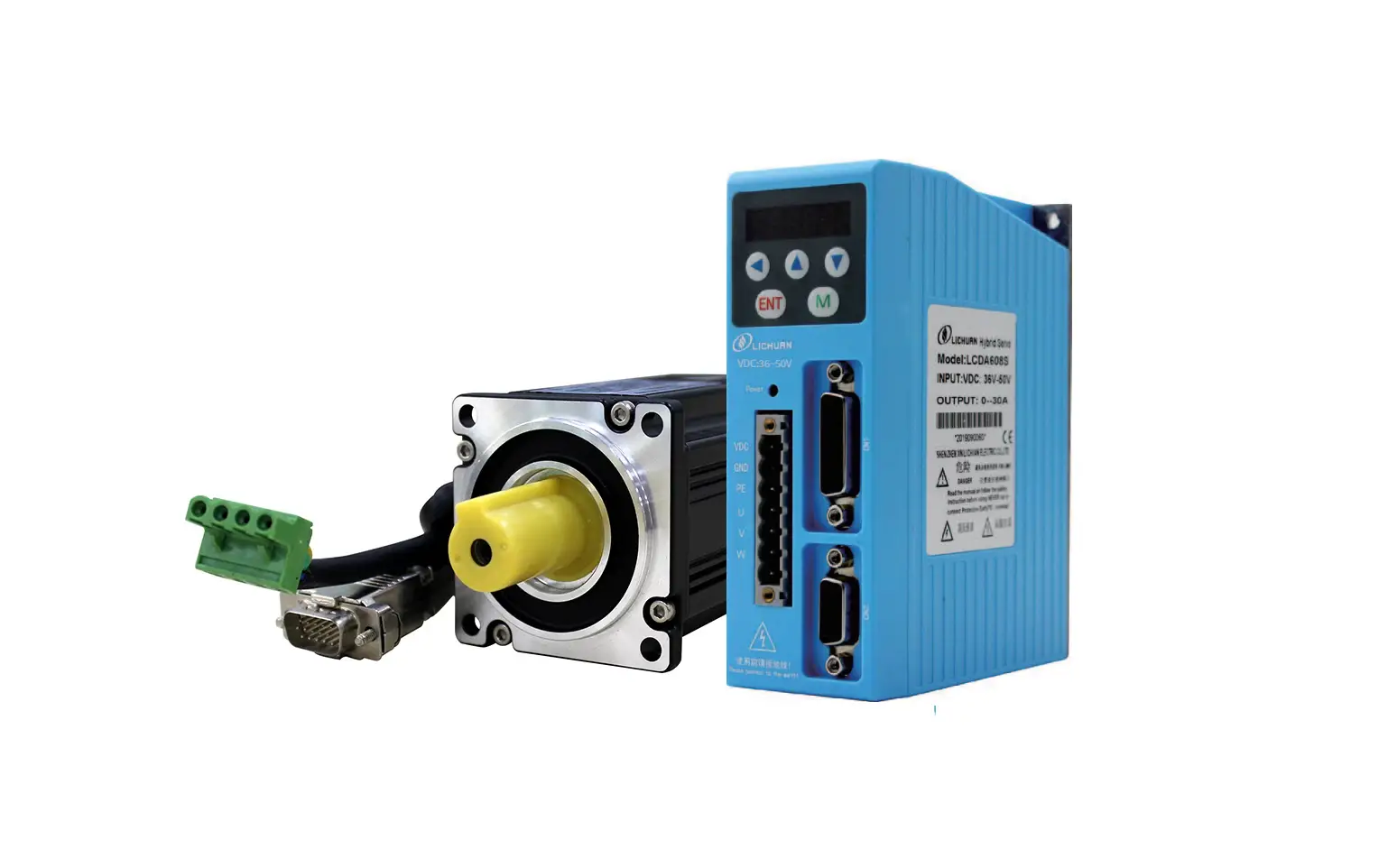
LiCHUAN LCDA-608S Digital DC Servo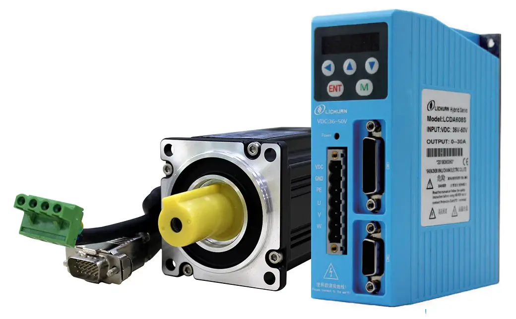
Installation
Electrical index
- Voltage input range:DC : 36V~50V
- Maximum output current: 30A
- Pulse form: pulse + direction, CW / CCW
- Logic input current: 10 ~ 20mA
- Impulse response frequency: 0 ~ 200kHz
- Insulation resistance: 500M
Environmental indicators
- Storage temperature: -20 ℃ ~ 80 ℃
- Operating temperature: 0 ℃ ~ 55 ℃
- Humidity: 90% RH (non-condensing)
- Vibration frequency: less than 0.5G (4.9m / s 2) 10Hz ~60Hz (not continuous operation)
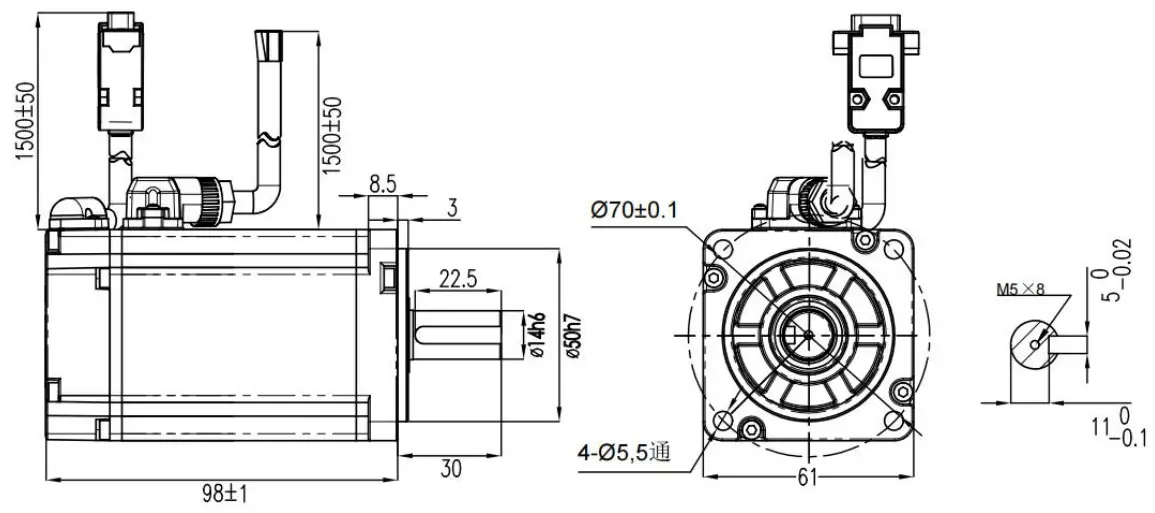
Installation dimension drawing(mm)
P1 Driver installation dimensions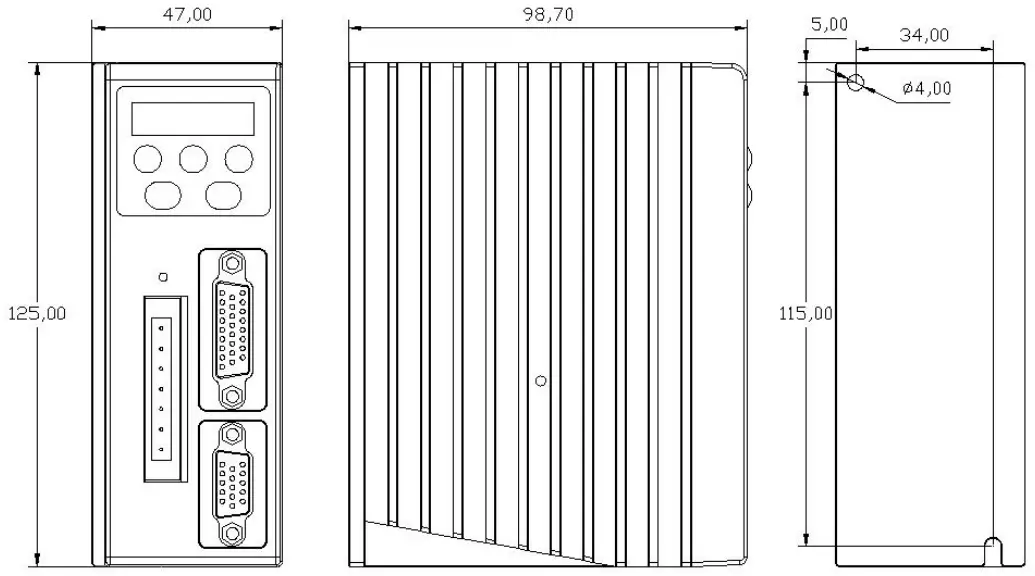
Wiring
Driver terminal description
Definition of power terminals
| No. | Symbol | Function definition |
| 1 | DC+ | DC power supply terminal (36-50VDC) 400W recommended 48V |
| 2 | GND | |
| 3 | BR | External braking resistor |
| 4 | U | Motor power line terminal See the label on the motor for the wiring color |
| 5 | V | |
| 6 | W | |
| 7 | none |
Driver control terminal definition (26 pin DB plug)
Terminal welding surface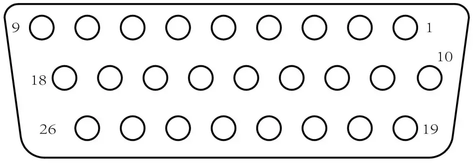
| Pin | Symbol | Definition | Pin | Symbol | Definition |
| 1 | PUL- | Pulse input negative | 18 | ALM- | Alarm output negative |
| 2 | PUL+ | Pulse input positive | 10 | +5V | 5V power output |
| 3 | DIR- | Direction input negative | 26 | GND | Internal power ground |
| 4 | DIR+ | Direction input positive | 20 | EA+ | A phase differential pulse feedback output |
| 5 | ENA+ | Enable input positive | 21 | EA- | |
| 6 | ENA- | Enable input negative | 22 | EB+ | B-phase differential |
| 7 | Pend+ | Positioning completion output is positive | 23 | EB- | C-pulse feedback output |
| 8 | Pend- | Positioning completion output is negative | 24 | EZ+ | Z-phase differential pulse feedback output |
| 9 | ALM+ | Alarm output is positive | 25 | EZ- |
Communication port pin definition (RJ45 network port)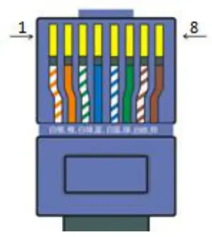
| Pin | Definition |
| 3 | GND |
| 5 | TXD |
| 7 | TXD |
Communication line with computer
| PC terminal (9-pin female) | Drive end (network port) | |
| 2(RXD) | 5(TXD) | |
| 3(TXD) | 7(RXD) | |
| 5(GND) | 3(GND) |
Definition of driver encoder terminals (15-pin DBplug)
| Pin | Symbol | Color | Definition |
| 1 | EA+ | yellow | Encoder A signal is positive |
| 2 | EB+ | green | Encoder B signal is positive |
| 3 | GND | black | Encoder power ground |
| 4 | EZ+ | Brown | Encoder Z signal is positive |
| 6 | HW+ | White | Encoder W signal is positive |
| 7 | HU+ | gray | Encoder U signal is positive |
| 8 | HV+ | Orange | Encoder V signal is positive |
| 10 | EZ- | Brown black | Encoder Z signal negative |
| 11 | EA- | Yellow black | Encoder A signal negative |
| 12 | EB- | Green black | Encoder B signal negative |
| 13 | VCC | red | Encoder + 5V input |
Control port wiring
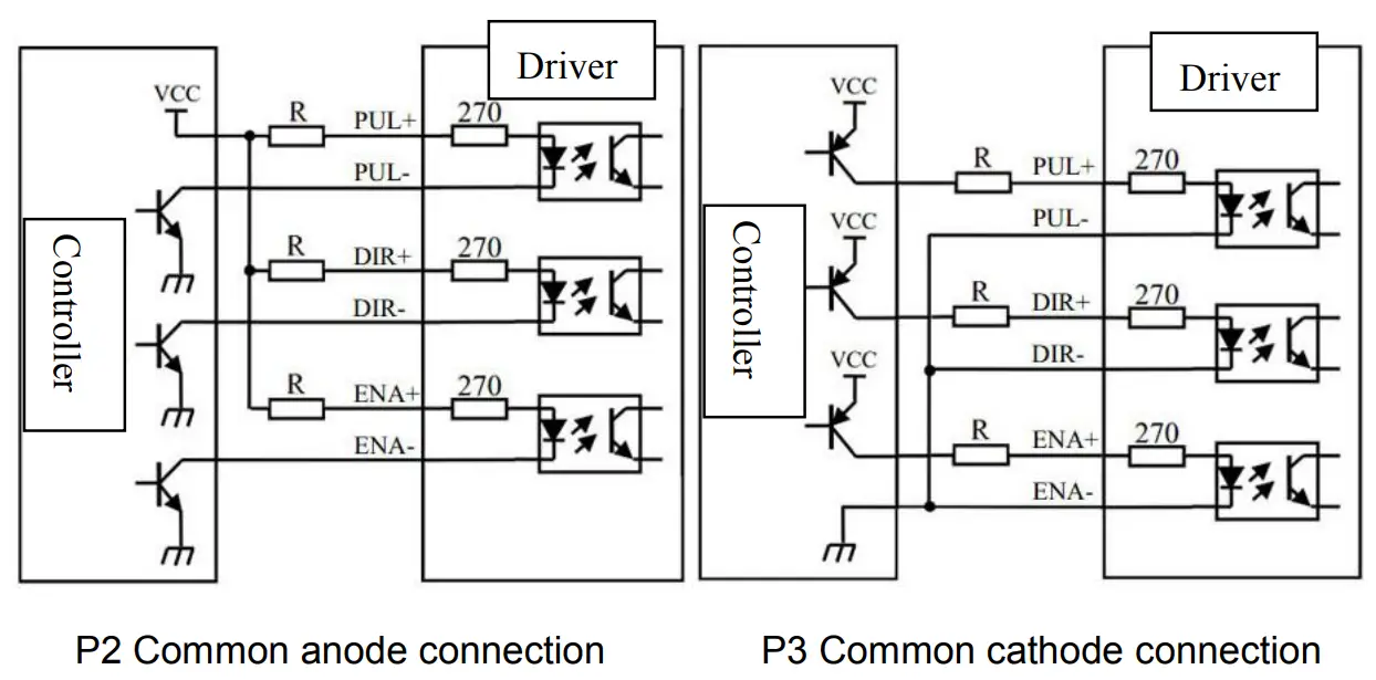
P4 Differential signal input and output signal connection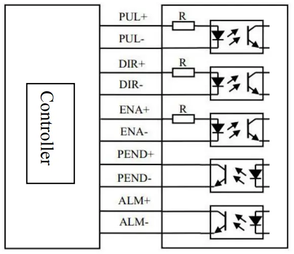
Note:
- When the control signal voltage VCC = 24V, the current limiting resistor R = 1.5K;
- When the control signal voltage VCC = 5V, the current limiting resistor R = 0;
Control signal timing diagram
P6 Motor brake signaltiming diagram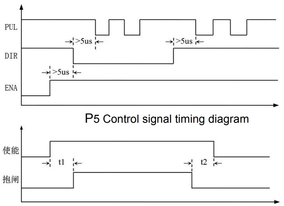
Note:
- Delay brake opening time
- Delay brake closing time
Parameter settings
This series of drivers can be set directly through the keypad of the driver. The debugging panel and debugging steps are as follows:
Introduction to the debug panel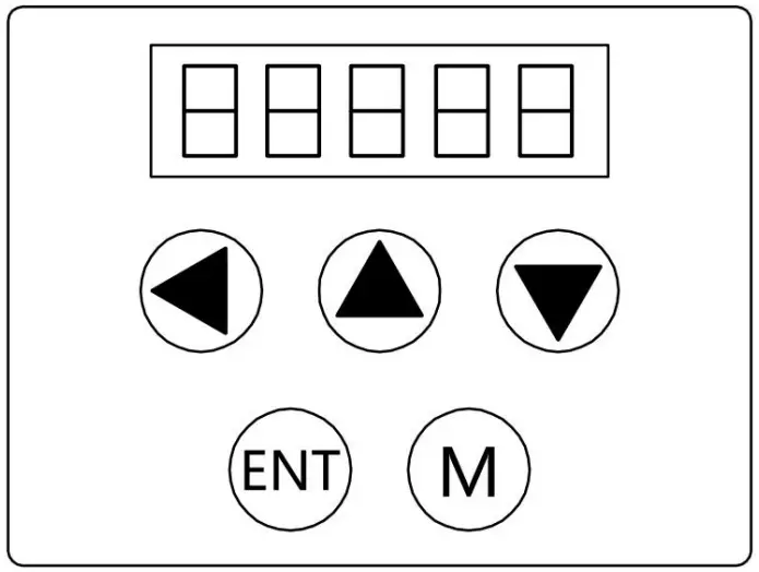
| Key | Key Description |
 | Input bit (blinking) shift left |
 | Switch sub menus, increase values |
 | Switch sub-menus, decrease values |
 | Enter submenu, confirm input |
 | Switchable between modes |
Data monitoring
| LED display | Description |
 | The current position error is converted to the number of code disk lines |
 | Current speed feedback (rpm) |
 | Current speed reference (rpm) |
 | Number of pulses after 4 times the frequency of the current position feedback code disc, calculated from power-on initialization |
 | Given the original number of pulses at the current position, it is calculated from power-on initialization |
 | Current current peak (mA) |
 | Displays the current fault value. |
Operating procedures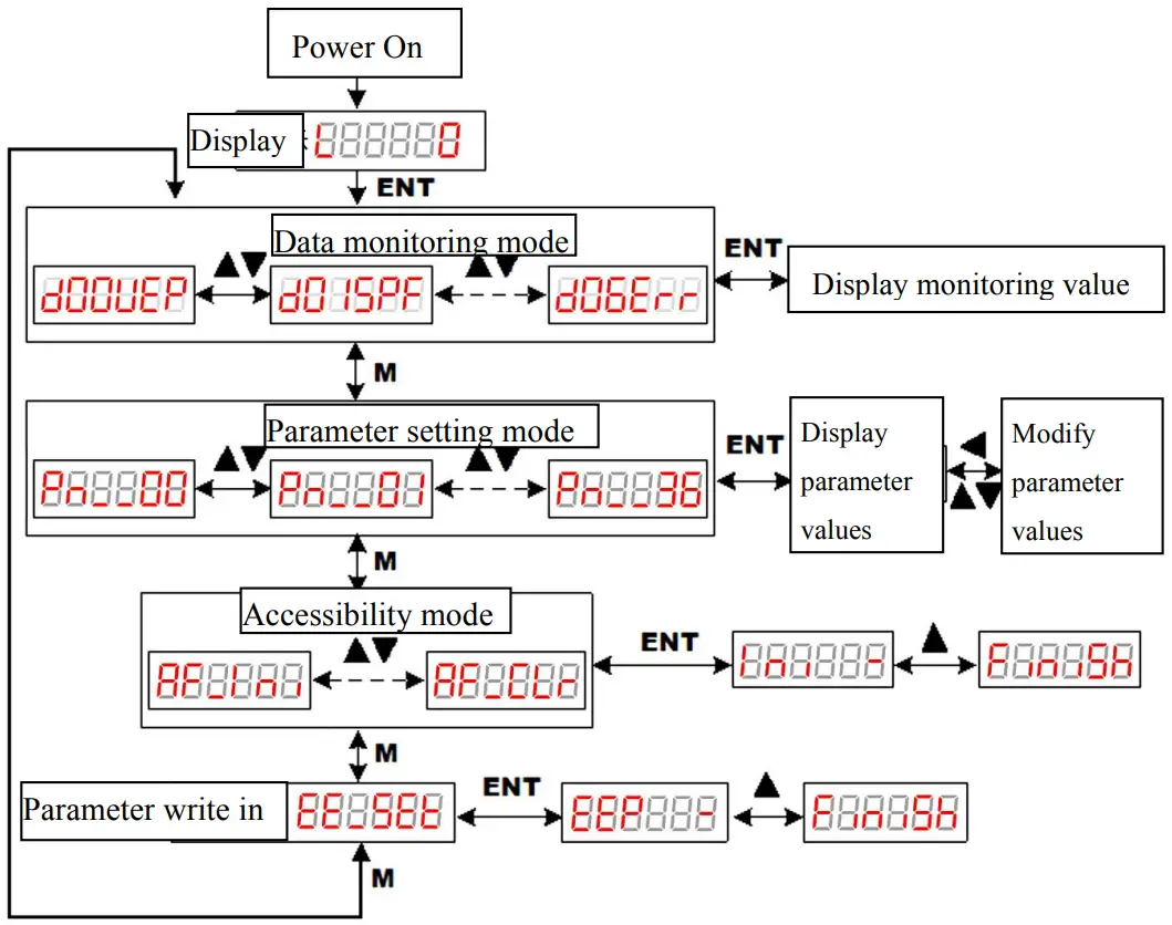
Restore factory settings: Press key change to“AF_Ini”,then press key ,display “InI -”,then press![]() key ,the setting is down when the screen display “Finish”
key ,the setting is down when the screen display “Finish”
Clear alarm log: Press key change to“AF_CLr”,then press key, display “CLr -”,then press ![]() key ,the setting is down when the screen display “Finish”。
key ,the setting is down when the screen display “Finish”。
Parameter write in: Press key change to “EE_SEt”,then press key,display“EEP -”,then long press ![]() key for 5 seconds,the setting is down when the screen display “Finish”。
key for 5 seconds,the setting is down when the screen display “Finish”。
Specific parameter description
| Serial number | Parameter name | Parameter range | Defaults | Description |
| PA_000 | Electronic gear molecule | 1~32767 | 1 | |
| PA_001 | Electronic Gear Denominator | 1~32767 | 1 | |
| PA_002 | Input pulse filter cutoff frequency | 1~500 | 70 | |
| PA_003 | Speed sampling filter cutoff frequency | 100~2000 | 800 | |
| PA_004 | Current loop filter cutoff frequency | 350~2500 | 1100 | |
| PA_005 | Single and double pulse selection | 0~1 | 0 | 0:PUL+DIR 1:CCW/CW |
| PA_006 | Pulse active edge selection | 0~1 | 0 | |
| PA_007 | Positive direction level selection | 0~1 | 0 | |
| PA_008 | Control mode selection | 1~3 | 1 |
|
| PA_009 | Current loop scale factor | 200~32767 | ||
| PA_010 | Current loop integration coefficient | 0~32767 | ||
| PA_011 | Speed loop high-speed proportionality factor | 100~32767 | 3200 | |
| PA_012 | Speed loop low speed proportionality factor | 100~32767 | 2900 | |
| PA_013 | Speed loop integration coefficient | 0~32767 | 400 | |
| PA_014 | Position loop high-speed proportionality factor | 10~32767 | 2700 | |
| PA_015 | Position loop low speed proportionality factor | 10~32767 | 2200 | |
| PA_016 | Speed feedforward coefficient | 0~1000 | 400 | |
| PA_017 | Acceleration feed-forward coefficient | 0~32767 | 0 | |
| PA_018 | Gravity compensation coefficient | 20~180 | 100 | |
| PA_019 | Friction compensation method | 0~1 | 0 | |
| PA_020 | Friction compensation coefficient | 20~180 | 100 | |
| PA_021 | Peak current limit | 100~19456 | 18432 | |
| PA_022 | Continuous output current limit | 35~8687 | 8687 |
| PA_023 | Maximum speed limit | 1~100 | 100 | |
| PA_024 | Number of motor pole pairs(Do not change it) | 2~30 | 4 | |
| PA_025 | Yard line | 1000~32768 | 1024 | |
|
PA_026 | Motor selection (Divided into 4 pairs of poles and 5 pairs of poles motors) |
1~100 |
13 | 12:200W(4 pairs) 13:400W(4 pairs) 14:200W(5 pairs) 15:400W(5 pairs) |
| PA_027 | Manufacturer parameters | 0~32767 | 40 | |
| PA_028 | First notch point frequency | 500~5000 | 5000 | |
| PA_029 | First notch point depth | 0~20 | 8 | |
| PA_030 | Second notch point frequency | 500~5000 | 5000 | |
| PA_031 | Second notch point depth | 0~20 | 8 | |
| PA_032 | Number of command loops for the first segment | 0~32767 | 50 | |
| PA_033 | Low position of the first position instruction | 0~32767 | 0 | |
| PA_034 | First speed | 7000~13000 | 10600 | |
| PA_035 | First period plus time | 1~200 | 100 | |
| PA_036 | Number of second position command cycles | 0~32767 | 50 | |
| PA_037 | Low position of second position instruction | 0~32767 | 0 | |
| PA_038 | Second speed | 7000~13000 | 9400 | |
| PA_039 | Second period plus time | 1~200 | 100 | |
| PA_040 | 3rd position command circle | 0~32767 | 50 | |
| PA_041 | The third position instruction low | 0~32767 | 0 | |
| PA_042 | Third speed | 7000~13000 | 11200 | |
| PA_043 | Third period plus time | 1~200 | 100 | |
| PA_044 | The fourth stage position command | 0~32767 | 50 | |
| PA_045 | Low position of fourth position command | 0~32767 | 0 | |
| PA_046 | Fourth speed | 7000~13000 | 8800 | |
| PA_047 | Fourth period plus time | 1~200 | 100 | |
| PA_048 | Position tracking error limit | 0~32767 | 10000 | |
| PA_049 | In-place output error limit | 0~32767 | 4 |
Alarm processing
| Alarm code | Fault description | Troubleshooting |
| ER_001 | Overcurrent alarm |
|
| ER_002 | Over-voltage alarm |
|
| ER_003 ER_010 | Encoder failure |
|
| ER_004 | Overload alarm | The motor is stalled or the load is too large. |
| ER_005 | Phase sequence error |
|
| ER_007 | Excessive position deviation |
|
| ER_008 | Brake failure |
|
Appendix: DC servo motor parameters
400WDC servo motor parameter
| Project | Parameter | Unit | |
| Rated output power | 400 | W | |
| Rated voltage | 48 | VDC | |
| Rated speed | 3000 | rpm | |
| Peak speed | 3200 | rpm | |
| Rated torque | 1.27 | N.M | |
| Peak torque | 2.54 | N.M | |
| Rated current | 11+/-10% | Ams | |
| Peak current | 22+/-10% | Ams | |
| Torque coefficient | 0.12+/-10% | N.m/Ams | |
| Back EMF Constant | 7.0+/-10% | V/KRPM | |
| Line-to-line resistance | 0.27+/-10% | Ω | |
| Line-to-line inductance | 0.56+/-20% | mH | |
| Moment of inertia | 0.58+/-10% | Kg.m2*10-4 | |
| Number of pole pairs | 5 | pairs of poles | |
| Encoder | 2500PPR | Incremental | |
| Motor protection level | IP54 | ||
| Brake holding torque | No | N.m | |
| Brake holding voltage | No. | DC | |
| Insulation class | F class | ||
| Insulation resistor | >200mΩ | DC500V | |
| Turn around | Seen from the motor shaft extension end, it rotates counterclockwise (CCW) | ||