
REZNOR Multiple Heater Control Relay Kit
INSTRUCTION
CAUTION
- DO NOT use these multiple heater control options with a two-stage gas valve or a two-stage thermostat.
- These instructions are designed to assist a qualified electrician in installing this multiple heater control kit.
- All electrical wiring and connections, including electrical grounding, MUST be in accordance with the National Electric Code ANSI/NFPA No. 70 (latest edition) or, in Canada, with the Canadian Electrical Code, Part 1, CSA Standard C22.1. In addition, the installation must comply with local ordinances and applicable gas company requirements.
- These relay kits are designed to permit the control of up to six heaters (one control unit and up to five additional non-control units) with one single-stage thermostat or with a time clock and single or multiple single-stage thermostats. For maximum safety, multiple control is installed in the low-voltage circuit. Interruption of the supply voltage is not recommended.
- Refer to the installation manual provided with the heater for important safety information.
- Pay attention to all dangers, warnings, cautions, and notes highlighted in this manual. Safety markings should not be ignored and are used frequently throughout to designate a degree or level of seriousness.
- Model/option/voltage applicability is listed in Table 1 and kit components are listed in Table 2. Ensure that all components listed in Table 2 are available before beginning installation.
Model/Voltage/Option Applicability
| Table 1. Model/Voltage/Option Applicability | |||
| Voltage/Phase | Option for Control Unit | Option for Non-Control Unit(s) | No. of Non-Control Units Permitted |
| 208/1, 230/1 | CL31 | CL32 | 4* |
| *Except as follows: unit size 400 can have five (5) additional non-control units, unit size 800 can have three (3) additional non-control units, and unit size 1200 can have two (2) additional non-control units. | |||
Relay Kit Components
| Table 2. Relay Kit Components | ||||
| Item No.* | Component | Description | Option** | |
| CL31 | CL32 | |||
| PN (Quantity) | ||||
| — | Option package PN | 1041280 (1) | 1041286 (1) | |
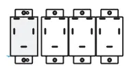
| 1 | Relay assembly*** | Assembly | 208365 (2) | 208365 (1) |
| 1A | Relay | With wires and wire terminals | 18549 (2) | 18549 (1) |
| 2 | Screw | #8-18 × 1/2, for securing relay bracket | 38529 (4) | 38529 (2) |
| 3 | Label | Wiring diagram | 208185 (2) | 208185 (1) |
| *See Figure 1. | ||||
| **Option CL31 includes components for one control unit and one additional unit. Option CL32 includes components for each additional non-control unit. | ||||
| ***Consists of a relay plug, 24VAC, DPDT (PN 211411) and a relay socket (PN 211415) with wires (all with terminals): 42-inch red, 42-inch white, 6-inch blue, and 6-inch brown. If replacing a previously-used relay only (PN 98118), order kit (PN 263527) to replace. | ||||
INSTALLATION
Install the relay kit as follows. Item numbers refer to Table 2.
- Turn OFF gas and electric power.
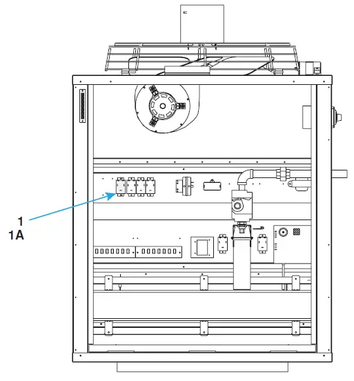
- Install relay assembly on the control unit and on all non-control units (see Figure 1):
- Remove the access panel from the main heat section.
- Position relay assembly (1 and 1A) on the control panel and secure using screws (2).
 CAUTION
Be careful not to short thermostat leads to a metal surface. Doing so will cause the transformer to fail and require replacement.
- Connect relay (1A) to TEW-type control wiring in accordance with model-specific wiring diagram label (3) from kit. Do not exceed length and distance listed in Table 3.
 CAUTION
Control Wiring Specifications
| Table 3. Control Wiring Specifications | ||
| Gauge | Maximum Length (Feet (Meters))* | Maximum Distance (Feet (Meters)) |
| 12 | 2100 (640) | 1050 (320) |
| 14 | 1300 (457) | 650 (198) |
| 18 | 500 (152) | 250 (76) |
| *For a complete circuit. | ||
Install wiring diagram label:
- For future reference, check the appropriate box for the heater function—PRIMARY HEATER for the control unit or SECONDARY HEATER for the non-control unit—on the wiring diagram label (3).
- Locate the required wiring diagram label position inside of the access panel.
- Wipe the surface with a clean, dry cloth.
- Remove the label backing and adhere the label to the unit.
Restore system to service:
- Turn ON gas and electric power.
- Light heater in accordance with lighting instructions.
- Check for proper operation.
Specifications and illustrations are subject to change without notice or incurring obligations. The latest version of this manual is available at www.reznorhvac.com.
©2022 Nortek Global HVAC LLC, O’Fallon, MO. All rights reserved.
LDAP-CL31,32 (06-22) 1041278-A


