
REZNOR RHC21-P Air Heater Modules
INTRODUCTION
This addendum has been produced for the propane fired (RHC21-P) version of the RHC21 4000 and RHC21 8000 Air Heater Module. This addendum highlights the differences between the RHC21-P and the standard RHC21 4000 and RHC21 8000 Air Heater Module.
This addendum must be read in conjunction with the applicable RHC21 4000 or RHC21 8000 Air Heater Module Installation Manual. Particular attention must be paid to the “Important Notice to Installers” and Health and Safety” Sections of the installation manual.
This addendum does not supersede or replace the applicable RHC21 4000 or RHC21 8000 Air Heater Installation Manual in any way.
RHC21-P air heaters are designed to operate on propane gas (G31). Refer to the technical data given on pages 3 to 6 inclusive of this document and to the data plate on the air heater module for details of supply pressures.
Technical Data RHC21 4000 Series
This table replaces “Table 1 – Specifications” given on Page 8 of the RHC21 4000 Installation Manual
| Model | 4024-05-P | 4050-06-P | 4060-07-P | 4075-09-P | 4100-12-P | |
| Combustion air & flue type Indoor | B23 / B53 / C13 / C33 / C53 | |||||
| Combustion air & flue type External | Rooftop | |||||
| Heat Input High Fire (Hs) 1 | kW | 28.80 | 61.50 | 77.60 | 91.50 | 120.00 |
| Heat Input Low Fire (Hs) 1 | kW | 18.60 | 16.00 | 23.00 | 32.00 | 37.00 |
| Heat Input High Fire (Hi) 2 | kW | 26.42 | 56.42 | 71.19 | 83.94 | 110.09 |
| Heat Input Low Fire (Hi) 2 | kW | 17.06 | 14.68 | 21.10 | 29.36 | 33.94 |
| Heat Output H2 High Fire 4 | kW | 24.09 | 52.43 | 66.22 | 78.06 | 103.05 |
| Heat Output H2 Low Fire 4 | kW | 16.45 | 14.58 | 20.88 | 29.02 | 33.59 |
| Gas Consumption High Fire (Hs) G31 3 | m³/h | 1.08 | 2.31 | 2.92 | 3.44 | 4.51 |
| Gas Consumption Low Fire (Hs) G31 3 | m³/h | 0.70 | 0.60 | 0.87 | 1.20 | 1.39 |
| Gas Consumption High Fire (Hs) G31 3 | l/h | 4.02 | 8.58 | 10.83 | 12.77 | 16.75 |
| Gas Consumption Low Fire (Hs) G31 3 | l/h | 2.60 | 2.23 | 3.21 | 4.47 | 5.16 |
| Gas Consumption High Fire (Hs) G31 3 | kg/h | 2.06 | 4.40 | 5.55 | 6.54 | 8.58 |
| Gas Consumption Low Fire (Hs) G31 3 | kg/h | 1.33 | 1.14 | 1.64 | 2.29 | 2.64 |
| Gas Service Connection | 1/2″ | 3/4″ | 3/4″ | 3/4″ | 3/4″ | |
| Flue & Combustion Air Connection Collars (Indoor) | Ø mm | 100 | 130 | 130 | 130 | 130 |
| Condensation Connection / Outlet | Ø mm | 22 OD | ||||
| Minimum V1 Airflow at 15°C with Heat Output H1 6 | m³/h | 2500 | 3900 | 4700 | 5700 | 7500 |
| kW | TBA | TBA | TBA | TBA | TBA | |
| Temperature Rise at V1 Airflow | K | TBA | TBA | TBA | TBA | TBA |
| Minimum V2 Airflow at 15°C with Heat Output H2 5 | m³/h | 2880 | 5950 | 7150 | 8800 | 11700 |
| Temperature Rise at V2 Airflow | K | 25 | 26 | 28 | 26 | 26 |
| Electrical Connection | 1 Phase | 230V 1N~50Hz | ||||
| Total Electric Rating | kW | 0.08 | 0.30 | 0.30 | 0.30 | 0.28 |
| Appliance Weight (net) | kg | 31 | 90 | 100 | 120 | 149 |
| Protection Grade | IP | 20 (Indoor) / X4D (External) | ||||
- Refers to gross calorific value of fuel
- Refers to net calorific value of fuel
- Propane gas: G31 Hs 95.65 MJ/m³ @ 15°C and 1013.25 mbar
- Heat output depends on airflow – heat output H2 only for airflows above V2.
- H2 = heat output at airflow V2
- H1 = heat output at airflow V1.
Technical Data RHC21 8000 Series
This table replaces “Table 1 – Specifications” given on Page 8 of the RHC21 8000 Installation Manual
| Model | 8045-09-P | 8075-15-P | 8075-09-P | 8100-12-P | 8150M18-P | 8200M24-P | |
| Combustion air & flue type Indoor | B23 / B53 / C13 / C33 / C53 | ||||||
| Combustion air & flue type External | Rooftop | ||||||
| Heat Input High Fire (Hs) 1 | kW | 56.00 | 91.50 | 91.50 | 120.00 | 183.00 | 240.00 |
| Heat Input Low Fire (Hs) 1 | kW | 16.80 | 32.00 | 32.00 | 37.00 | 64.00 | 79.00 |
| Heat Input High Fire (Hi) 2 | kW | 51.38 | 83.94 | 83.94 | 110.09 | 167.89 | 220.18 |
| Heat Input Low Fire (Hi) 2 | kW | 15.41 | 29.36 | 29.36 | 33.94 | 58.72 | 72.48 |
| Heat Output H2 High Fire 4 | kW | 46.74 | 77.04 | 78.09 | 103.67 | 156.73 | 204.92 |
| Heat Output H2 Low Fire 4 | kW | 15.13 | 28.77 | 28.94 | 33.71 | 57.93 | 71.61 |
| Gas Consumption High Fire (Hs) G31 3 | m³/h | 2.11 | 3.44 | 3.44 | 4.51 | 6.88 | 9.03 |
| Gas Consumption Low Fire (Hs) G31 3 | m³/h | 0.63 | 1.20 | 1.20 | 1.39 | 2.41 | 2.97 |
| Gas Consumption High Fire (Hs) G31 3 | l/h | 7.82 | 12.77 | 12.77 | 16.75 | 25.54 | 33.50 |
| Gas Consumption Low Fire (Hs) G31 3 | l/h | 2.35 | 4.47 | 4.47 | 5.16 | 8.93 | 11.03 |
| Gas Consumption High Fire (Hs) G31 3 | kg/h | 4.00 | 6.54 | 6.54 | 8.58 | 13.08 | 17.15 |
| Gas Consumption Low Fire (Hs) G31 3 | kg/h | 1.20 | 2.29 | 2.29 | 2.64 | 4.57 | 5.65 |
| Gas Service Connection | 3/4″ | 3/4″ | 3/4″ | 3/4″ | 1 1/4″ | 1 1/4″ | |
| Flue & Combustion Air Connection Collars (Indoor) | Ø mm | 130 | 130 | 130 | 130 | 130 | 180 |
| Condensation Connection / Outlet | Ø mm | 22 OD | |||||
| Minimum V1 Airflow at 15°C with Heat Output H1 6 | m³/h | 5650 | 9300 | 9300 | 12400 | 18200 | 23300 |
| kW | TBA | TBA | TBA | TBA | TBA | TBA | |
| Temperature Rise at V1 Airflow | K | TBA | TBA | TBA | TBA | TBA | TBA |
| Minimum V2 Airflow at 15°C with Heat Output H2 5 | m³/h | 6600 | 11900 | 10790 | 14300 | 21000 | 24000 |
| Temperature Rise at V2 Airflow | K | 21 | 19 | 22 | 22 | 22 | 25 |
| Electrical Connection | 1 Phase | 230V 1N~50Hz | |||||
| Total Electric Rating | kW | 0.30 | 0.30 | 0.30 | 0.28 | 0.60 | 0.56 |
| Appliance Weight (net) | kg | 87 | 140 | 110 | 145 | 230 | 305 |
| Protection Grade | IP | 20 (Indoor) / X4D (External) | |||||
- Refers to gross calorific value of fuel
- Refers to net calorific value of fuel
- Propane gas: G31 Hs 95.65 MJ/m³ @ 15°C and 1013.25 mbar
- Heat output depends on airflow – heat output H2 only for airflows above V2.
- H2 = heat output at airflow V2
- H1 = heat output at airflow V1.
Nominal Combustion Values RHC21 4000 Series
This table replaces “Table 2 – Nominal Combustion Values and Flue Gas Properties” given on Page 9 of the RHC21 4000 Installation Manual
| Model | 4024-05-P | 4050-06-P | 4060-07-P | 4075-09-P | 4100-12-P | |
| CO2 at High Fire (Throttle) G31 | % | 9.40 | 9.40 | 9.80 | 9.80 | 9.80 |
| CO | ppm | < 50 ppm | ||||
| CO2 at Low Fire (Offset) G31 | % | 8.80 | 8.80 | 9.00 | 9.00 | 9.00 |
| CO | ppm | < 50 ppm | ||||
| Flue Gas Temperature High Fire ΔT | °C | 168 | 136 | 139 | 140 | 129 |
| Flue Gas Temperature Low Fire ΔT | °C | 67 | 17 | 24 | 24 | 26 |
| Mass Flow Rate Flue Gases High Fire G31 | kg/h | 30.57 | 64.67 | 71.93 | 84.00 | 109.10 |
| Flue Pressure at Maximum Flue Resistance | Pa | 5 | 8 | 9 | 14 | 14 |
| Thermal Efficiency High Fire NCV | % | 91.19 | 92.93 | 93.02 | 92.99 | 93.60 |
| Thermal Efficiency Low Fire NCV | % | 96.42 | 99.30 | 98.95 | 98.84 | 98.96 |
| Gas Valve Orifice Size | mm | 4.4 | 6.0 | 6.8 | 6.8 | 7.4 |
Nominal Combustion Values RHC21 8000 Series
This table replaces “Table 2 – Nominal Combustion Values and Flue Gas Properties” given on Page 9 of the RHC21 8000 Installation Manual
| Model | 8045-09-P | 8075-15-P | 8075-09-P | 8100-12-P | 8150M18- P | 8200M24- P | |
| CO2 at High Fire (Throttle) G31 | % | 9.40 | 9.80 | 9.60 | 9.70 | 9.70 | 9.70 |
| CO | ppm | < 50 ppm | |||||
| CO2 at Low Fire (Offset) G31 | % | 8.60 | 8.90 | 8.80 | 8.90 | 8.90 | 8.80 |
| CO | ppm | < 50 ppm | |||||
| Flue Gas Temperature High Fire ΔT | °C | 171 | 162 | 137 | 116 | 132 | 138 |
| Flue Gas Temperature Low Fire ΔT | °C | 36 | 40 | 30 | 17 | 29 | 26 |
| Thermal Efficiency High Fire NCV | % | 90.98 | 93.02 | 91.78 | 94.17 | 93.35 | 93.07 |
| Thermal Efficiency Low Fire NCV | % | 98.18 | 98.59 | 97.99 | 99.31 | 98.66 | 98.80 |
| Mass Flow Rate Flue Gases High Fire G31 | kg/h | 59.81 | 86.19 | 90.40 | 116.00 | 175.16 | 227.53 |
| Flue Pressure at Maximum Flue Resistance | Pa | 2 | 6 | 9 | 18 | 23 | 9 |
| Gas Valve Orifice Size | mm | 6.0 | 6.8 | 6.8 | 7.4 | 6.8 x 2 | 7.4 x 2 |
Gas Supply – Propane
This information replaces the information given in “Section 4.10 Gas Supply” of the RHC21 4000 and RHC21 8000 Installation Manual regarding Gas Types
RHC21-P 4000 and 8000 heaters are designed to operate on propane gas (G31). Check that the gas supply, gas category and gas inlet pressure is in accordance with the information given on the unit data plate. To let the unit function at maximal heat output, the gas supply pipe MUST be correctly sized.
Gas Supply Details – Propane Gas
This table details the gas supply properties and is to be read in conjunction with the information given in “Section 4.10 Gas Supply” of the RHC21 4000 and RHC21 8000 Installation Manual regarding Gas Types
| Country | Gas Category | Gas Type | Nominal Supply Pressure (mbar) | Minimum Supply Pressure (mbar) | Maximum Supply Pressure (mbar) |
| CZ, DK, HU, MT, NL, RO | I3P (30) | Propane Gas (G31) | 30 | 25 | 35 |
| BE, CH, CZ, ES, FR, GB, GR, HR, IE, IT, LU, PL, PT, SI, SK, TR | I3P (37) | Propane Gas (G31) | 37 | 25 | 45 |
| AT, BE, CH, CZ, DE, ES, FR, GB, GR, HU, NL, SK | I3P (50) | Propane Gas (G31) | 50 | 42.5 | 57.5 |
Pre-Start Checks – Propane Gas
This information must be read in addition to the information given in “Section 5.3 – Pre-Start Checks” of the RHC21 4000 and RHC21 8000 Installation Manual
Ensure RHC21 heaters have a link cable fitted between internal wiring terminals GS / GS. Do not proceed if this link is missing.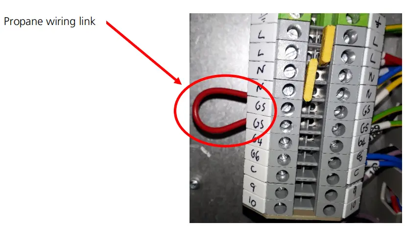
Verify ignition controller program key matches the resistance value as shown in nominal combustion value table.
Note: model 8200 has a different program key when converted for use on propane gas. All other models use the same program key for both natural and propane gas
Gas Conversion – Propane
This information replaces in its entirety the information given in “Section 5.8 – Gas Conversion” of the RHC21 4000 and RHC21 8000 Installation Manual
RHC21-P heaters are designed to operate on propane gas type G31. To modify for use on an alternative listed gas type, contact the appliance manufacturer for further information.
Nominal Combustion Values with Service Door Closed – Propane RHC21 4000
This table replaces “Table 10 – Nominal Combustion Values with Service Door Closed” given in the RHC21 4000 Installation Manual
| Model | 4024-05-P | 4050-06-P | 4060-07-P | 4075-09-P | 4100-12-P | |
| CO2 at High Fire (Throttle) G31 | % | 9.40 | 9.40 | 9.80 | 9.80 | 9.80 |
| CO | ppm | < 50 ppm | ||||
| Throttle turns from closed | 2.25 out | 3.5 out | 4.5 out | 4.5 out | 14 in | |
| CO2 at Low Fire (Offset) G31 | % | 8.80 | 8.80 | 9.00 | 9.00 | 9.00 |
| CO | ppm | < 50 ppm | ||||
| Low Fire Offset Pressure G31 | Pa | -50 | -5 | -19 | -44 | -9 |
| Flue Gas Temperature High Fire ΔT | °C | 168 | 136 | 139 | 140 | 129 |
| Flue Gas Temperature Low Fire ΔT | °C | 67 | 17 | 24 | 24 | 26 |
| Flue Pressure at Maximum Flue Resistance | Pa | 5 | 8 | 9 | 14 | 14 |
| Mass Flow Rate Flue Gases High Fire G31 | kg/h | 30.57 | 64.67 | 71.93 | 84.00 | 109.10 |
| Thermal Efficiency High Fire NCV | % | 91.19 | 92.93 | 93.02 | 92.99 | 93.60 |
| Thermal Efficiency Low Fire NCV | % | 96.42 | 99.30 | 98.95 | 98.84 | 98.96 |
| Ignition Controller Program Key Top Burner | Ω | N/A | N/A | N/A | N/A | N/A |
| Ignition Controller Program Key Bottom Burner | Ω | 1,000 | 3,300 | 4,700 | 6,800 | 10,000 |
| Gas Valve Orifice Size | mm | 4.4 | 6.0 | 6.8 | 6.8 | 7.4 |
Nominal Combustion Values with Service Door Closed – Propane RHC21 8000
This table replaces “Table 10 – Nominal Combustion Values with Service Door Closed” given in the RHC21 8000 Installation Manual
| Model | 8045-09- P | 8075-15- P | 8075-09- P | 8100-12- P | 8150M18 -P | 8200M24 -P | |
| CO2 at High Fire (Throttle) G31 | % | 9.40 | 9.80 | 9.60 | 9.70 | 9.70 | 9.70 |
| CO | ppm | < 50 ppm | |||||
| Throttle turns from closed Top Burner | N/A | N/A | N/A | N/A | 4 out | 34 in | |
| Throttle turns from closed Bottom / Single Burner | 3 out | 5 out | 4 out | 21 in | 4 out | 34 in | |
| CO2 at Low Fire (Offset) G31 | % | 8.60 | 8.90 | 8.80 | 8.90 | 8.90 | 8.80 |
| CO | ppm | < 50 ppm | |||||
| Low Fire Offset Pressure (G31) Top Burner | Pa | N/A | N/A | N/A | N/A | -55 | -34 |
| Low Fire Offset Pressure (G31) Bottom / Single Burner | Pa | -10 | -58 | -46 | -14 | -62 | -23 |
| Flue Gas Temperature High Fire ΔT | °C | 171 | 162 | 137 | 116 | 132 | 138 |
| Flue Gas Temperature Low Fire ΔT | °C | 36 | 40 | 30 | 17 | 29 | 26 |
| Thermal Efficiency High Fire NCV | % | 90.98 | 93.02 | 91.78 | 94.17 | 93.35 | 93.07 |
| Thermal Efficiency Low Fire NCV | % | 98.18 | 98.59 | 97.99 | 99.31 | 98.66 | 98.80 |
| Flue Pressure at Maximum Flue Resistance | Pa | 2 | 6 | 9 | 18 | 23 | 9 |
| Mass Flow Rate Flue Gases High Fire G31 | kg/h | 59.81 | 86.19 | 90.40 | 116.00 | 175.16 | 227.53 |
| Ignition Controller Program Key Top Burner | Ω | N/A | N/A | N/A | N/A | 22,000 | 56,000 |
| Ignition Controller Program Key Bottom Burner | Ω | 1,000 | 4,700 | 3,300 | 6,800 | 22,000 | 56,000 |
| Gas Valve Orifice Size | mm | 6.0 | 6.8 | 6.8 | 7.4 | 6.8 x 2 | 7.4 x 2 |
Maintenance – Propane
This information must be read in addition to the information given in “Section 7.1 – Replacement of Gas Valve” of the RHC21 4000 and RHC21 8000 Installation Manual
RHC21-P models have an orifice fitted between the gas valve and venturi. This orifice should be retained and refitted when replacing the gas valve or venturi to ensure correct appliance operation.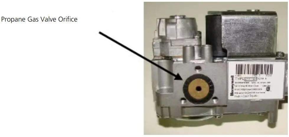
Cleaning and Replacement of Burner Probes – Propane
This information must be read in addition to the information given in “Section 7.6 – Cleaning and
Replacement of Burner Probes” of the RHC21 4000 and RHC21 8000 Installation Manual
RHC21-P models 4100-12-P, 8075-15-P, 8100-12-P and 8200M24-P have a special spark probe assembly. Dimensions for checking are as follows: –
Length of probe = 79.4mm long probe, 43.2mm short probe.
4.1mm +/- 0.5mm gap between probes.
Angle of probes 22.3°
Spare Parts – Propane
This information must be read in addition to the information given in “Section 9 – Parts Listing” of the RHC21 4000 and RHC21 8000 Installation Manual
| Description | Part Number | Application |
| 4.4mm gas valve orifice | 1037652 | 4024-05-P |
| 6.0mm gas valve orifice | 03-25800-02 | 4050-06-P, 8045-09-P |
| 6.8mm gas valve orifice | 1037654 | 4060-07-P, 4075-09-P, 8075-09-P, 8150M18-P x 2 |
| 7.4mm gas valve orifice & O-ring | 1037655 | 4100-12-P, 8100-12-P, 8200M24-P x 2 |
| Propane Gas Selection (GS) Jumper | 1030922 | All |
| Spark Probe c/w Lead | 1037848 | 4100-12-P, 8075-15-P 8100-12-P, 8200M24-P x 2 |
ErP Table – G31 Propane RHC21 4000
This information replaces the information given in “Section 11 – ErP Tables” of the RHC21 4000 Installation Manual
| Model | RHC21 | 4024- 05-P | 4050- 06-P | 4060- 07-P | 4075- 09-P | 4100- 12-P | ||||
| Item | Symbol | Units | ||||||||
| Capacity | ||||||||||
| Rated heating capacity | Pnom | kW | 24.1 | 52.4 | 66.2 | 78.1 | 103.0 | |||
| Minimum capacity | Pmin | kW | 16.5 | 14.6 | 20.9 | 29.0 | 33.6 | |||
| Electrical Power consumption | ||||||||||
| At rated heating capacity | elmax | kW | 0.040 | 0.123 | 0.115 | 0.151 | 0.174 | |||
| At minimal capacity | elmin | kW | 0.008 | 0.012 | 0.018 | 0.021 | 0.029 | |||
| In standby mode | elsb | kW | 0.001 | 0.001 | 0.001 | 0.001 | 0.001 | |||
| Useful efficiency | ||||||||||
| Useful efficiency at rated heating capacity | η th, nom | % | 83.7 | 85.3 | 85.3 | 85.3 | 85.9 | |||
| Useful efficiency at minimum capacity | η th, min | % | 88.5 | 91.1 | 90.8 | 90.7 | 90.8 | |||
| Other items | ||||||||||
| Envelope loss factor | Fenv | % | 0.0 | 0.0 | 0.0 | 0.0 | 0.0 | |||
| Flame consumption | Pign | kW | 0.0 | 0.0 | 0.0 | 0.0 | 0.0 | |||
| Emissions of nitrogen oxides (input energy GCV | NOx | Mg/kWh | 62 | 67 | 68 | 59 | 66 | |||
| Emission efficiency | η s, flow | % | 93.9 | 96.7 | 96.2 | 96.0 | 96.3 | |||
| ErP seasonal space heating energy efficiency | η s | % | 79.5 | 87.1 | 86.3 | 85.6 | 86.4 | |||
| Thermal efficiency at rated heating capacity NCV | η | % | 91.2 | 92.9 | 93.0 | 93.0 | 93.6 | |||
ErP Table – G31 Propane RHC21 8000
This information replaces the information given in “Section 11 – ErP Tables” of the RHC21 8000 Installation Manual
| Model | RHC21 | 8045- 09-P | 8075- 09-P | 80750 15-P | 8100- 12-P | 8150 M18- P | 8200 M24- P | |||
| Item | Symbol | Units | ||||||||
| Capacity | ||||||||||
| Rated heating capacity | Pnom | kW | 46.7 | 78.1 | 77.0 | 103.7 | 156.7 | 204.9 | ||
| Minimum capacity | Pmin | kW | 15.1 | 28.9 | 28.8 | 33.7 | 57.9 | 71.6 | ||
| Electrical Power consumption | ||||||||||
| At rated heating capacity | elmax | kW | 0.113 | 0.187 | 0.162 | 0.187 | 0.39 | 0.43 | ||
| At minimal capacity | elmin | kW | 0.014 | 0.021 | 0.022 | 0.016 | 0.050 | 0.056 | ||
| In standby mode | elsb | kW | 0.001 | 0.001 | 0.001 | 0.001 | 0.001 | 0.001 | ||
| Useful efficiency | ||||||||||
| Useful efficiency at rated heating capacity | η th, nom | % | 83.5 | 85.3 | 84.2 | 86.4 | 85.6 | 85.4 | ||
| Useful efficiency at minimum capacity | η th, min | % | 90.1 | 90.4 | 89.9 | 91.1 | 90.5 | 90.6 | ||
| Other items | ||||||||||
| Envelope loss factor | Fenv | % | 0.0 | 0.0 | 0.0 | 0.0 | 0.0 | 0.0 | ||
| Flame consumption | Pign | kW | 0.0 | 0.0 | 0.0 | 0.0 | 0.0 | 0.0 | ||
| Emissions of nitrogen oxides (input energy GCV | NOx | Mg/kWh | 60 | 56 | 69 | 58 | 68 | 65 | ||
| Emission efficiency | η s, flow | % | 97.1 | 96.7 | 97.1 | 97.0 | 96.6 | 96.3 | ||
| ErP seasonal space heating energy efficiency | η s | % | 86.2 | 86.1 | 85.8 | 87.4 | 86.1 | 86.0 | ||
| Thermal efficiency at rated heating capacity NCV | η | % | 91.0 | 93.0 | 91.8 | 94.2 | 93.4 | 93.1 | ||
CUSTOMER SERVICE
NORTEK GLOBAL HVAC (UK) LTD
Fens Pool Avenue
Brierley Hill
West Midlands DY5 1QA
United Kingdom
Tel +44 (0)1384 489700
Fax +44 (0)1384 489707
[email protected]
www.reznor.eu
Current full Part No.
Installation Instruction Addendum
RHC21 4000 and 8000 Propane
January 2022 D301383 Issue 0
Nortek Global HVAC is a registered trademark of Nortek Global HVAC Limited. Because of the continuous product innovation, Nortek Global HVAC reserves the right to change product specification without due notice.
![]()


![Reznor Gas-fired, Balanced-flue Or Power-vented Unit Heaters User Manual[rhc 4000(m) Djl,rhc 4000(m) Rjl]](https://static-data1.manualsee.com/1/img/497/70217/2021/02/Reznor-Gas-Fired-Balanced-Flue-or-Power-Vented-Unit-Heaters-User-ManualRHC-4000M-DJLRHC-4000M-RJL.jpg "Reznor Gas-fired, Balanced-flue Or Power-vented Unit Heaters User Manual[rhc 4000(m) Djl,rhc 4000(m) Rjl]")


