REZNOR UBX Gas Conversion Unit Heaters
GENERAL INFORMATION
These gas conversion kits are for standard power-vent or separated-combustion heaters equipped with either a
single-stage or two-stage gas valve.
Table 1. Model Configuration | |||
| Model | Configuration | Model | Configuration |
| UBX, UDBP | Standard power-vent blower-type | UBZ, UDBS | Separated-combustion blower-type |
| UDX, UDAP | Standard power-vent fan-type | UDZ, UDAS | Separated-combustion fan-type |
Model Identification
When converting fuels, it is necessary to have the complete heater model. The identifying model number can be
found on the heater rating plate. The rating plate identifies only original equipment so also compare the label on the gas valve with the description listed.
- Refer to the installation manual provided with the heater for important safety information.
- Pay attention to all dangers, warnings, cautions, and notes highlighted in this manual. Safety markings should not be ignored and are used frequently throughout to designate a degree or level of seriousness.
|
- All gas conversion must be done by a qualified service person in accordance with these instructions and in compliance with all codes and requirements. In Canada, gas conversion shall be carried out in accordance with the requirements of the Provincial Authorities having jurisdiction and in accordance with the requirements of the CAN/CGA-B149.1 and CAN/CGA-B149.2 installation code.
- The gas burner in this gas-fired equipment is designed to provide safe complete combustion. However, if the installation does not permit the burner to receive the proper supply of combustion air, complete combustion may not occur. The result is incomplete combustion, which produces carbon monoxide, a poisonous gas that can cause death.
- Safe operation of indirect-fired gas burning equipment requires a properly-operating vent system that vents all flue products to the outside atmosphere. Failure to provide proper venting will result in a health hazard that could cause serious personal injury or death.
- On separated combustion heaters, install either the horizontal or vertical combustion air/vent system illustrated in the heater venting manual, using the concentric adapter supplied. For all heater installations, always comply with the combustion air requirements in the installation codes and instructions. Standard power vent heaters installed in a confined space must be supplied with air for combustion as required by code and in the heater installation manual. Combustion air at the burner should be regulated only by manufacturer-provided equipment. Never restrict or otherwise alter the supply of combustion air to any heater. Maintain the vent or vent/combustion air system in structurally sound and proper operating condition.
- Improper installation, adjustment, alteration, service, or maintenance can cause property damage, injury, or death. Read the installation, operation and maintenance instructions thoroughly before installing or servicing this equipment.
- The conversion kit is to be selected and installed by a qualified service person in accordance with these instructions and in compliance with all codes and requirements of authorities having jurisdiction. Failure to follow instructions could result in death, serious injury, and/or property damage. The qualified agency performing this work assumes responsibility for this conversion.
GENERAL INFORMATION—CONTINUED
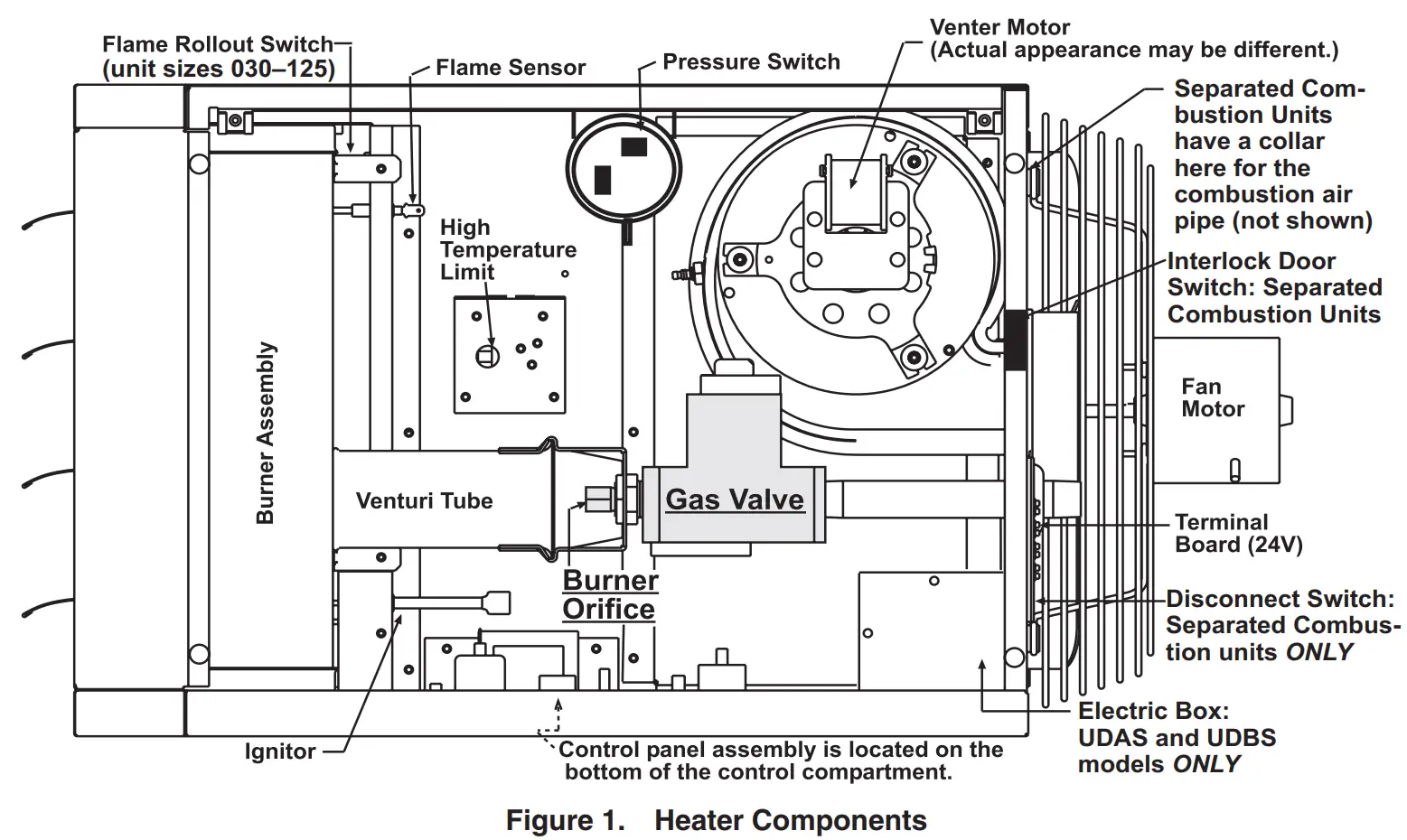
Heater Component Locations
Heater component locations are shown in Figure 1.
CONVERSION KIT SELECTION
Each conversion kit includes two or three spring kits and burner orifices for multiple unit sizes. Some parts will not be used—carefully select the parts to be used. Refer to Table 2 for components common to all kits. Refer to Table 3 or Table 4 for kit-specific components for current models UBX, UBZ, UDX, and UDZ. Refer to Table 5 or Table 6 for kit-specific components for legacy models UDAP, UDAS, UDBP, and UDBS. Refer to Table 7 for burner orifices.
| NOTE: When ordering a conversion kit for legacy model UDAP, UDAS, UDBP, or UDBS, either kit PN—current or legacy as shown in Table 5 and Table 6—is applicable. |
Table 2. Conversion Kit Common Components—All Models | ||
| Component | Description | PN |
| Tape | Conversion | 64391 |
| Disk | Propane (included in all NG to LP kits) | 3775 |
| Natural gas (included in all LP to NG kits) | 1401 | |
| Label | High-elevation adjustment (used only at installation elevations >2000 feet (>610 meters)) | 197062 |
| Burner orifice | Refer to Table 7 | |
| Table 3. Natural Gas to Propane Kit-Specific Components—UBX, UBZ, UDZ, and UDZ Models | |||||||||
|
Component |
Description | Gas Valve (Honeywell Model No.) | |||||||
| 1/2-Inch, Single- Stage (VR8105K2942, VR8205K2957, o VR8215T1239) | 1/2-Inch, Single- Stage (VR8105K2942, VR8205K2957, or VR8215T1239) or 1/2-Inch, Two-Stage (VR8105N2949 or VR8205N2921) | 1/2-Inch, Single-Stage (VR8205K2957 or VR8215T1239) or 1/2-Inch, Two-Stage (VR8205N2921) | 1/2-Inch, Single-Stage (VR8205K2957 or VR8215T1239), 3/4-Inch Single Stage (VR8305K4241), or 1/2-Inch, Two-Stage (VR8205N2921 or VR8305N4297) | 3/4-Inch Single Stage (VR8305K4241) or 3/4-Inch, Two-Stage (VR8305N4297) | |||||
| Unit Size | |||||||||
| 030, 045 | 060, 075 | 100, 125 | 150, 175 | 200, 225, 250 | 300, 350, 400 | ||||
| Model | |||||||||
| UBX, UBZ | UDX, UDZ | UBX, UBZ | UDX, UDZ | All | |||||
| Kit PN | |||||||||
| 1036541R | 1036536R | 1036542R | 1036537R | 1036538R | 1036539R | 1036540R | 1036543R | ||
| Component PN | |||||||||
| Spring kit | #393691 for single- stage valve VR8105, VR8205, or VR8305 | 98720 | 98720 | 98720 | 98720 | ||||
| #396221 for single- stage valve VR8215 | 260605 | 260605 | 260605 | 260605 | — | ||||
| #396021 for two- stage valve VR8105, VR8205, or VR8305 | — | 197207 | 197207 | 197207 | |||||
| Air restrictor plate | 1-3/16-inch (30 mm) opening | 203078 | — | — | — | — | |||
| 1-3/8-inch (35 mm) opening | — | 196687 | |||||||
| 1-9/16-inch (40 mm) opening | — | 202051 | — | ||||||
| 1-3/4-inch (44 mm) opening | 196688 | 196688 | |||||||
| Table 4. Propane to Natural Gas Kit-Specific Components—UBX, UBZ, UDZ, and UDZ Models | |||||||
| Component | Description | Gas Valve (Honeywell Model No.) | |||||
| 1/2-Inch, Single Stage (VR8105K2959, VR8205K2965, or VR8215T5214) | 1/2-Inch, Single-Stage (VR85K2959, VR8205K2965, or VR8215T5214) or 1/2-Inch, Two-Stage (VR8105N2931 or VR8205N2913) | 1/2-Inch, Single-Stage (VR85K2959, VR8205K2965, or VR8215T5214), 3/4-Inch Single-Stage (VR8305N4258), 1/2-Inch, Two-Stage (VR8105N2931 or VR8205N2913), or 3/4-Inch, Two-Stage (VR8305N4289) |
3/4-Inch Single-Stage (VR8305N4258) or 3/4-Inch, Two-Stage (VR8305N4289) | ||||
| Unit Size | |||||||
| 030, 045 | 060, 075 | 100, 125 | 150, 175 | 200, 225, 250 | 300, 350, 400 | ||
| Kit PN | |||||||
| 1036544R | 1036545R | 1036546R | 1036547R | 1036548R | 1036549R | ||
| Component PN | |||||||
| Spring kit | #394588 for single-stage valve VR8105, VR8205, or VR8305 | 98721 | 98721 | 98721 | |||
| #396222 for single-stage valve VR8215 | 261651 | 261651 | 261651 | — | |||
| #396205 for two-stage valve VR8105, VR8205, or VR8305 | — | 197208 | 197208 | 197208 | |||
Table 5. Natural Gas to Propane Kit-Specific Components—UDAP, UDAS, UDBP, and UDBS Models | |||||||||
|
Component |
Description | Gas Valve (Honeywell Model No.) | |||||||
| 1/2-Inch, Single- Stage (VR8105K2942, VR8205K2957, or VR8215T1239) | 1/2-Inch, Single- Stage (VR8105K2942, VR8205K2957, or VR8215T1239) or 1/2-Inch, Two-Stage (VR8105N2949 or VR8205N2921) | 1/2-Inch, Single-Stage (VR8205K2957 or VR8215T1239) or 1/2-Inch, Two-Stage (VR8205N2921) | 1/2-Inch, Single-Stage (VR8205K2957 or VR8215T1239), 3/4-Inch Single Stage (VR8305K4241), or 1/2-Inch, Two-Stage (VR8205N2921 or VR8305N4297) |
3/4-Inch Single-Stage (VR8305K4241) or 3/4-Inch, Two-Stage (VR8305N4297) | |||||
| Unit Size | |||||||||
| 030, 045 | 060, 075 | 100, 125 | 150, 175 | 200, 225, 250 | 300, 350, 400 | ||||
| Model | |||||||||
| UDAP, UDAS | UDBP, UDBS | UDAP, UDAS | UDBP, UDBS | All | |||||
| Kit PN | |||||||||
| 269835 or 1036541R | 269840 or 1036536R | 269836 or 1036542R | 269841 or 1036537R | 269837 or 1036538R | 269838 or 1036539R | 269839 or 1036540R | 201732 or 1036543R | ||
| Component PN | |||||||||
| Spring kit | #393691 for single-stage valve VR8105, VR8205, or VR8305 | 98720 | 98720 | 98720 | 98720 | ||||
| #396221 for single- stage valve VR8215 | 260605 | 260605 | 260605 | 260605 | — | ||||
| #396021 for two-stage valve VR8105, VR8205, or VR8305 | — | 197207 | 197207 | 197207 | |||||
| Air restrictor plate | 1-3/8-inch (35 mm) opening | 196687 | — | — | — |
— | |||
| 1-3/16-inch (30 mm) opening | — | 203078 | |||||||
| 1-3/4-inch (44 mm) opening | — | 196688 | — | 196688* | |||||
| 1-9/16-inch (40 mm) opening | — | 202051 | — | ||||||
| *The plate from kit PN 269837 is not used on unit size 125 models. The plate from kit PN 269838 is not used on unit size 175 models for residential or commercial applications. | |||||||||
Table 6. Propane to Natural Gas Kit-Specific Components—UDAP, UDAS, UDBP, and UDBS Models | |||||||
| Component | Description | Gas Valve (Honeywell Model No.) | |||||
| 1/2-Inch, Single Stage (VR8105K2959, VR8205K2965, or VR8215T5214) | 1/2-Inch, Single-Stage (VR85K2959, VR8205K2965, or VR8215T5214) or 1/2-Inch, Two-Stage (VR8105N2931 or VR8205N2913) | 1/2-Inch, Single Stage (VR85K2959, VR8205K2965, or VR8215T5214), 3/4-Inch Single-Stage (VR8305N4258), 1/2-Inch, Two-Stage (VR8105N2931 or VR8205N2913), or 3/4-Inch, Two-Stage (VR8305N4289) | 3/4-Inch Single Stage (VR8305N4258) or 3/4-Inch, Two Stage (VR8305N4289) | ||||
| Unit Size | |||||||
| 030, 045 | 060, 075 | 100, 125 | 150, 175 | 200, 225, 250 | 300, 350, 400 | ||
| Kit PN | |||||||
| 269851 or 1036544R | 269852 or 1036545R | 269853 or 1036546R | 269854 or 1036547R | 269855 or 1036548R | 201738 or 1036549R | ||
| Component PN | |||||||
| Spring kit | #394588 for single-stage valve VR8105, VR8205, or VR8305 | 98721 | 98721 | 98721 | |||
| #396222 for single-stage valve VR8215 | 261651 | 261651 | 261651 | — | |||
| #396205 for two-stage valve VR8105, VR8205, or VR8305 | — | 197208 | 197208 | 197208 | |||
| Table 7. Burner Orifices—All Models | |||
| Unit Size | Model | Natural Gas | Propane |
| Orifice Size/Marking (PN) | |||
| 030 | UDAP, UDAS, UDBP, UDBS | #37 (196853) | 1.6 mm (196844) |
| UBX, UBZ, UDX, UDZ | #39 (196852) | ||
| 045 | UDAP, UDAS, UDBP, UDBS | #30 (196838) | #48 (196845) |
| UBX, UBZ, UDX, UDZ | 3.1 mm (120144) | ||
| 060 | UDAP, UDAS, UDBP, UDBS | 3.7 mm (196839) | 2.3 mm (196846) |
| UBX, UBZ, UDX, UDZ | #28 (124969) | 2.25 mm (1034350) | |
| 075 | UDAP, UDAS, UDBP, UDBS | #19 (196855) | #39 (196852) |
| UBX, UBZ, UDX, UDZ | #22 (196361) | #40 (120137) | |
| 100 | UDAP, UDAS, UDBP, UDBS | #10 (120158) | 3.0 mm (196854) |
| UBX, UBZ, UDX, UDZ | #14 (208247) | #32 (120141) | |
| 125 | UDAP, UDAS, UDBP, UDBS | #4 (196840) | 3.2 mm (196847) |
| UBX, UBZ, UDX, UDZ | #10 (120158) | 3.1 mm (120144) | |
| 150 | UDAP, UDAS, UDBP, UDBS | 5.9 mm (131581) | 9/64-inch (196898) |
| UBX, UBZ, UDX, UDZ | 5.6 mm (208243) | 3.5 mm (120148) | |
| 175 | UDAP, UDAS, UDBP, UDBS | E (196891) | #24 (196899) |
| UBX, UBZ, UDX, UDZ | 6.0 mm (208245) | #27 (120149) | |
| 200 | UDAP, UDAS, UDBP, UDBS | 6.8 mm (196892) | 4.1 mm (196900) |
| UBX, UBZ, UDX, UDZ | F (120167) | ||
| 225 | All | 6.95 mm (221121) | 11/64 inch (196901) |
| 250 | UDAP, UDAS, UDBP, UDBS | L (208255) | #14 (196902) |
| UBX, UBZ, UDX, UDZ | 4.60 mm (1034352) | ||
| 300 | UDAP, UDAS, UDBP, UDBS | 8.0 mm (221122) | #8 (196903) |
| UBX, UBZ, UDX, UDZ | 7.8 mm (208253) | ||
| 350 | UDAP, UDAS, UDBP, UDBS | 8.7 mm (221123) | #3 (196904) |
| UBX, UBZ, UDX, UDZ | 8.5 mm (1034354) | 5.4 mm (1034353) | |
| 400 | UDAP, UDAS, UDBP, UDBS | 9.6 mm (196897) | 5.8 mm (196905) |
| UBX, UBZ, UDX, UDZ | 9.2 mm (1034355) | ||
INSTALLATION
Install the conversion kit in accordance with the following steps. Ensure that the kit is correct for the size of the heater being serviced.
- Remove gas supply and electrical power:
a. Turn OFF gas supply at shutoff valve outside of heater.
b. Turn OFF electrical power.
c. Open control access panel. - Install regulator spring kit:
 WARNING
 Regulator spring kits are not interchangeable. Each kit must be used only in the model and type of gas valve for which the kit is designated. Verify compatibility before installing the regulator spring kit. a. Select regulator spring kit that corresponds with gas valve on heater. All gas conversion kits include one or two regulator spring kits for single-stage valve and one regulator spring for two-stage valve. Other included regulator spring kits will not be used.
b. Install regulator spring kit in accordance with gas valve manufacturer’s instructions (included with regulator spring kit). CAUTION After a new regulator spring kit is installed, it is necessary to adjust the spring by adjusting the
manifold pressure. This adjustment can be made only after the heater is in operation (refer to step 7).INSTALLATION—CONTINUED
- Remove or install air restrictor plate as necessary and replace burner orifice:
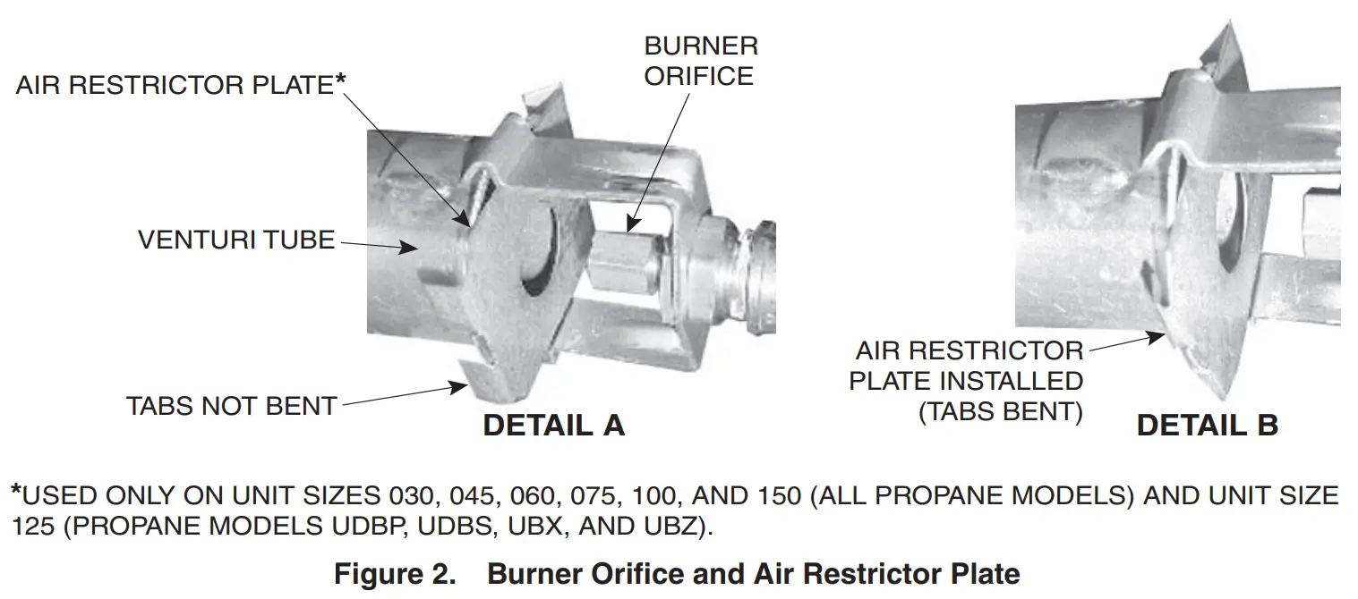
a. Carefully remove existing burner orifice (see Figure 2, DETAIL A). DANGER b. For unit sizes 030, 045, 060, 075, 100, and 150 (all models) and unit size 125 (models UDBP, UDBS, UBX, and UBZ), proceed to step c. For all other models/unit sizes, proceed to step e.
c. If converting from propane to natural gas, remove air restrictor plate as follows. If converting from natural gas to propane, install air restrictor plate in accordance with step d.
(1) See Figure 2, DETAIL B to locate air restrictor plate held in place on venturi tube by its bent tabs.
(2) Use pliers to carefully unbend tabs as shown in Figure 2, DETAIL A and remove air restrictor plate.
d. For natural gas to propane conversion, install air restrictor plate as follows:
(1) Refer to Table 3 or Table 5 to select correct air restrictor plate. Slide plate in place over venture tube opening so that its 45-degree angle is hooked over rear of venture tube (see Figure 2).
(2) While holding plate in position, use pliers to carefully bend tabs to lock plate in place (see Figure 2, DETAIL
B). Ensure that air restrictor is aligned and secure.
e. For all conversions, select replacement burner orifices in accordance with Table 7. All conversion kits include two or three burner orifices. Other included orifice(s) will not be used. WARNING Do not attempt to drill burner orifice. Use factory-supplied orifice only f. Install replacement burner orifice (see Figure 2, DETAIL A).

CAUTION
If the heater will be operated at an elevation >6,000 feet (>1,830 meters), a high-elevation pressure switch must be installed. NOTES:
- If the installation elevation is >6,000 feet (>1,830 meters), verify that the elevation on the rating plate or high-elevation label is >6,000 feet (>1,830 meters). If the rating plate or label does not indicate an elevation of >6,000 feet (>1,830 meters), order and install the appropriate high pressure switch kit.
- If the heater is equipped for installation at an elevation of >6,000 feet (>1,830 meters) and is being installed at a lower elevation, order and install the appropriate switch.
- Contact your distributor (refer to replacement parts manual) to select the factory-authorized replacement part.
- For installations at elevations >6,000 feet (>1,830 meters), replace pressure switch in accordance with Pressure Switch Replacement section in installation/operation/maintenance manual provided with unit.
- Restore electrical power and gas supply:
a. Turn ON electrical power.
b. Turn ON gas supply and relight heater, following instructions on heater. - Perform leak test:
a. Check all connections for gas leaks using commercial leak-detecting fluid or rich soap and water solution. Leaks are indicated by presence of bubbles.
b. If leak is detected, tighten connection. If leak cannot be stopped by tightening connection, replace part(s).NOTES:
- Conversion of a unit using these kits does not alter the input rate. Refer to the rating plate on the heater for the input rate and other appropriate information.
- If adjusted for high-elevation operation, the input rate will be affected.
- The high-elevation adjustment label is not used on units operated at elevations of ≤2,000 feet (≤610 meters).
- Adjust manifold (outlet) gas pressure in accordance with Measure and Adjust Manifold (Outlet) Gas Pressure section in installation/operation/maintenance manual provided with unit.
- Close control access panel.


Specifications and illustrations subject to change without notice or incurring obligations.
Latest version of this manual is available at www.reznorhvac.com.
©2022 Nortek Global HVAC LLC, O’Fallon, MO. All rights reserved.
UBX-UBZ-UDX-UDZ-GC (04-22) 1034364-D