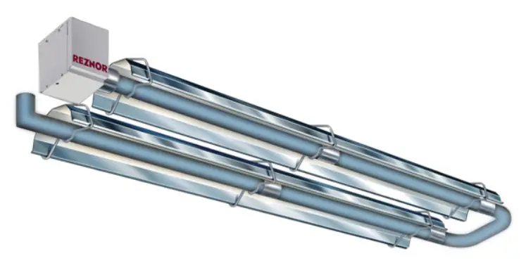
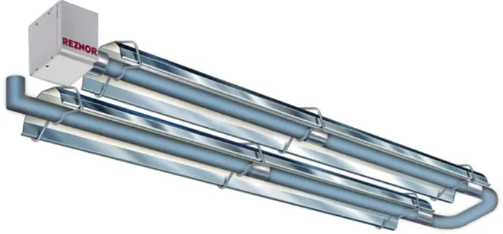
REZNOR VCS Radiant Heaters
Product Information
This product is a propane conversion kit for natural gas-fired radiant heaters. It is designed for use with models VCS, VCT, VPS, and VPT. The kit, labeled as Option DL2, includes various components necessary for converting the heater from natural gas to propane.
Danger:
There is no conversion kit available for unit size 200. Additionally, the following models should not be converted to propane if installed at elevations higher than 5,000 feet (>1,524 meters):
- Unit size 150 of all models with S40 tube configuration
- Unit size 170 of models VCS and VPS with S40 tube configuration
This kit is to be installed by a qualified service agency in accordance with these instructions and in compliance with all codes and requirements of authorities having jurisdiction. Improper installation, adjustment, alteration, service, and/or maintenance can cause property damage, injury, or death. In Canada, gas conversion shall be carried out in accordance with the requirements of the Provincial Authorities having jurisdiction and in accordance with the requirements of the CAN/CGA-B149.1 and CAN/CGA-B149.2 installation code. The qualified agency performing this work assumes responsibility for this conversion.
NOTE: There is no conversion kit available for unit size 200. Furthermore, the following models MUST NOT be converted to propane at installation elevations >5,000 feet (>1,524 meters): unit size 150 of all models with S40 tube configuration and unit size 170 of models VCS and VPS with S40 tube configuration.
General Information
- This kit is intended for natural gas units installed at elevations of 0–10,000 feet (0–3,045 meters). If the unit is already manufactured for propane, the only upgrade for elevation is fan orifice plate replacement.
- When converting fuels, it is necessary to have the complete heater model. The identifying model number can be found on the heater rating plate. The rating plate identifies only original equipment, so also compare the label on the gas valve with the description listed.
- Refer to the installation manual provided with the heater for important safety information.
- Ensure that all components listed in Table 1 are available before beginning installation.
Natural Gas to Propane Conversion Kit (Option DL2) Components
| Component | Description | Unit Size | Model | ||||||
| 060 | 080 | 100 | 125 | 150 | 170 | ||||
| Kit PN | |||||||||
| 1001412 | 1001413 | 1001414 | 1001415 | 1001416 | 1001417* | 1001418** | |||
| Component PN (Quantity)*** | |||||||||
| Grommet | 12.5 × 9.5 mm | 270412 | All | ||||||
| Washer | Retaining, M6 | 270459 | |||||||
| Flame plate | Propane | 269957 | 269958 | 269959 | 269960 | ||||
| Conversion kit | Gas valve | 270374 | |||||||
| Burner orifice plate | Propane | 269948 | 269949 | 269980 | 269951 | 269952 | 269953 | ||
| Fan orifice plate | Propane | 269924 | 269925 | 269929 | 269931 | 269933 | 269937 | ||
| 269925 | 269928 | 269932 | 269932 | 269934 | |||||
| 269928 | 269929 | 269933 | 269933 | 1011096 | |||||
| 269929 | 269930 | 269934 | 269934 | ||||||
| 1011095 | 1011096 | ||||||||
| Gasket | Burner assembly | 270366 (2) | |||||||
| Baffle plate | For vision burners | 270328 | — | ||||||
| Baffle plate screw | #8 × 1/2, SST | 270414 (2) | |||||||
| *For use with size 170 model VPS and VCS generation ZZ units—converts burner to size 150 generation BB. | |||||||||
| **For use with size 170 model VCT and VPT generation ZZ units and all generation BB units at installation elevations of 0–2,000 feet. | |||||||||
| ***Quantity is one (1) unless otherwise indicated. | |||||||||
| Component | Description | Unit Size | Model | ||||||
| 060 | 080 | 100 | 125 | 150 | 170 | ||||
| Kit PN | |||||||||
| 1001412 | 1001413 | 1001414 | 1001415 | 1001416 | 1001417* | 1001418** | |||
| Component PN (Quantity)*** | |||||||||
| Self-tapping screw | #6 × 3/8, BZP | 270450 (4) | — | VPS | |||||
| Plate | Fan flange | 269911 | |||||||
| Gasket | Fan flange plate | 270365 | |||||||
| Label | Conversion | 270653 (2) | 270655 (2) | 270657 (2) | 270659 (2) | 270661 (2) | 270661 (2) | 270663 (2) | VCS, VPS |
| 270654 (2) | 270656 (2) | 270658 (2) | 270660 (2) | 270662 (2) | — | 270664 (2) | VCT, VPT | ||
| Jet carrier | Propane | — | 270375 | All | |||||
| Gas orifice | Refer to Table 2 | ||||||||
| *For use with size 170 model VPS and VCS generation ZZ units—converts burner to size 150 generation BB. | |||||||||
| **For use with size 170 model VCT and VPT generation ZZ units and all generation BB units at installation elevations of 0–2,000 feet. | |||||||||
| ***Quantity is one (1) unless otherwise indicated. | |||||||||
Propane Gas Orifices
| Unit Size | ||||
| 060 | 080, 100 | 125 | 150 | 170 |
| PN (Orifice Size) | ||||
| 270398 (1.1 mm) | 270399 (1.3 mm) | 270400 (1.5 mm) | 270401 (1.7 mm) | 270401 (1.7 mm)* |
| 270403 (1.9 mm)** | ||||
| *For use with size 170 model VPS and VCS generation ZZ units—converts burner to size 150 generation BB. | ||||
| **For use with size 170 model VCT and VPT generation ZZ units and all generation BB units at installation elevations of 0–2,000 feet. | ||||
Product Usage Instructions
Installation
- Remove gas and electric supply:
- Shut OFF gas supply ahead of union at manual shutoff valve outside cabinet.
- Disconnect electrical power/control connections.
- Disconnect gas supply at union outside of cabinet using two wrenches.
- For models VCS, VCT, and VPT with ducted combustion air:
- Loosen hose clamp that secures flexible hose to fresh air inlet on side of burner cabinet and remove hose.
- Loosen setscrew on burner support casting and remove burner from emitter tube.
- Replace burner orifice plate:
- Remove and save four screws that secure burner assembly.

- Remove burner support casting and gasket . Discard gasket.

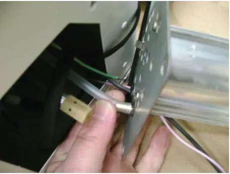
- Disconnect ignition, flame probe, and ground leads and pressure switch silicone tube .

- Remove and save three screws that secure existing burner orifice plate to burner tube and remove plate and gasket. Discard gasket.

- Remove retaining washer that secures impulse stud to burner orifice plate and remove stud.
- Orient replacement burner orifice plate with impulse stud and replacement retaining washer facing in correct direction and replacement cable grommet fitted to oblong hole in bottom of plate.

- Secure replacement burner orifice plate to burner tube using existing three screws.
- Remove and save four screws that secure burner assembly.
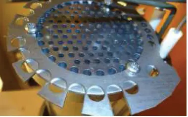
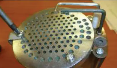
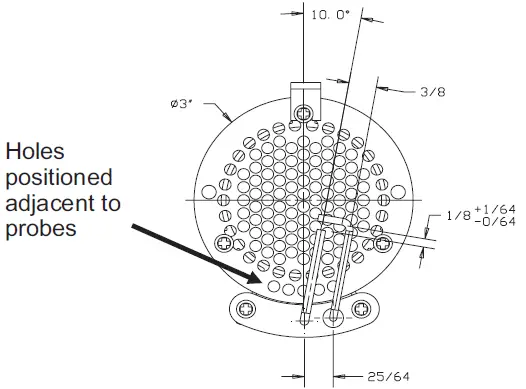
- Replace flame plate:
- Remove and save three screws that secure flame plate and burner head to burner tube.

- Remove flame plate. DO NOT remove burner head.
- Remove and discard anti-tip bracket

- Secure flame plate on top of burner head to burner tube using existing three screws. Ensure that five holes on outer ring are aligned properly.

- Remove and save three screws that secure flame plate and burner head to burner tube.
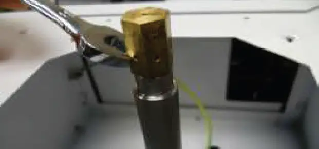
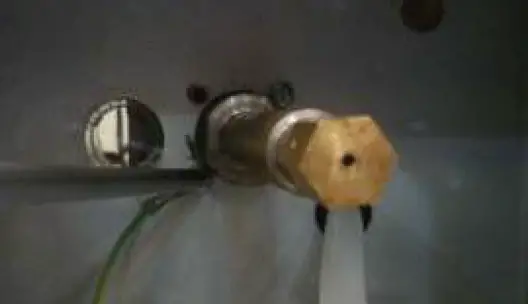
- Relace gas orifice:
- For unit sizes 060–150:
- Using wrench, unthread existing gas orifice from jet carrier.
- Using approved pipe joint compound and wrench, thread replacement gas orifice into jet carrier. DO NOT overtighten.

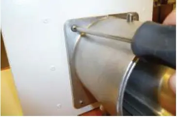
- For unit size 170 model VPS:
- Remove and save two screws from base of jet carrier. Note ground terminal connection.
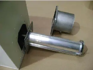
- Remove and save four screws that secure rear burner plate to burner housing and remove plate.
- Using wrench, unthread existing jet carrier/gas orifice from gas valve.
- Thread replacement gas orifice into replacement jet carrier.
- Using approved pipe joint compound and wrench, thread replacement jet carrier/gas orifice into gas valve. DO NOT overtighten.
- Re-install rear burner plate to burner housing and secure plate using existing four screws.
- Re-install existing two screws in base of jet carrier. Note ground terminal connection.

- For unit size 170 models VCS, VCT, and VPT:
- Remove and save two screws from base of jet carrier. Note ground terminal connection.
- Remove and save four screws that secure base plate and remove plate.
- Mark and disconnect gas valve wiring connections.
- Remove four screws that secure gas valve inlet plate to burner housing and remove plate.
- Remove gas valve rearwards and, using wrench, unthread existing jet carrier/gas orifice from gas valve.
- Thread replacement gas orifice into replacement jet carrier.
- Using approved pipe joint compound and wrench, thread replacement jet carrier/gas orifice into gas valve. DO NOT overtighten.
- Re-install gas valve inlet plate to burner housing and secure plate using existing four screws.
- Re-install existing two screws in base of jet carrier. Note ground terminal connection.

- For unit sizes 060–150:
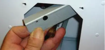
- For unit sizes 060, 080, and 100, install baffle plate:
NOTE: For model VCS and VCT units, two existing screws in the baffle plate mounting holes need to be removed.- Carefully position baffle plate inside combustion chamber.

- Align baffle plate holes with existing holes in burner cabinet and secure plate using two baffle plate screws.

- Carefully position baffle plate inside combustion chamber.
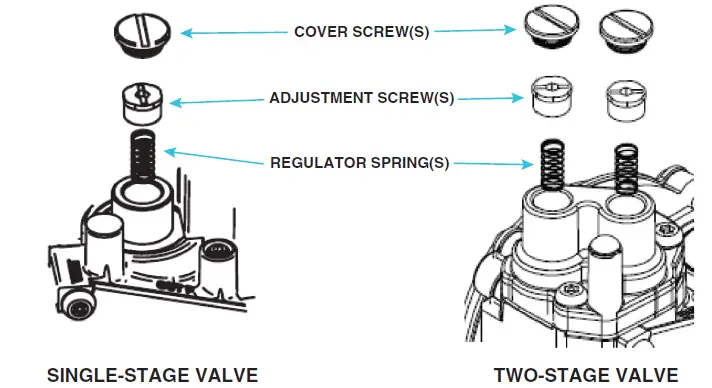
- Replace regulator springs in combination gas valve:
- Open access door/panel.
- Remove brass cover screw(s), plastic adjustment screw(s), and existing regulator spring(s) from combination gas valve regulator sleeve.
- Install replacement regulator spring(s) from gas valve conversion kit into regulator sleeve and thread adjustment screw approximately eight turns into sleeve.
- Set correct gas pressure in accordance with Table 3 by turning adjustment screw(s) IN (clockwise) to increase pressure or OUT (counterclockwise) to decrease pressure.
- Re-install cover screw(s) and adhere small round LP label(s) from gas valve conversion kit to top of cover screw(s).
- Close access door/panel.
- Adhere warning label from gas valve conversion kit where it can easily be seen on outside of burner cabinet.
NOTE: A 5-foot (1,524-mm) burner insert (PN 270489) is used in unit sizes 060, 080, and 100. A 3-foot (914-mm) burner insert (PN 1005500) is used in unit size 125. The burner insert is installed in the first emitter tube where it is joined to the second emitter tube. Gas Manifold Pressure for Propane Units
Installation Location Elevation (Feet (Meters)) Model Burner Setting Unit Size 170* 060 080 100 125 150 170 Gas Manifold Pressure (IN WC) US 0–2000 (0–610) VCS, VPS — 5.5 5.2 8.0 7.6 7.0 6.1 7.0 VCT, VPT Low 3.5 2.9 4.4 4.6 3.3 3.6 — High 5.5 5.2 8.0 7.6 7.0 6.1 2001–5000 (611–1525) VCS, VPS — 5.5 5.2 8.0 7.6 7.0 — 7.0 VCT, VPT Low 3.5 2.9 4.4 4.6 3.3 — High 5.5 5.2 8.0 7.6 7.0 5001–10,000 (1526–3045) VCS, VPS — 5.5 5.2 8.0 7.6 6.4 — 6.4 VCT, VPT Low 3.5 2.9 4.4 4.6 3.3 — High 5.5 5.2 8.0 7.6 6.4 Canada 0–2000 (0–610) VCS, VPS — 5.5 5.2 8.0 7.6 7.0 6.1 7.0 VCT, VPT Low 3.5 2.9 4.4 4.6 3.3 3.6 — High 5.5 5.2 8.0 7.6 7.0 6.1 2001–4500 (611–1373) VCS, VPS — 5.4 5.0 7.8 7.4 6.8 — 6.8 VCT, VPT Low 3.4 2.8 4.2 4.4 3.1 — High 5.4 5.0 7.8 7.4 6.8 *Generation ZZ units.
- If heater has burner insert(s), remove insert(s).
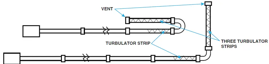
NOTE: The following units require additional turbulator strip(s) (PN 116019): unit size 100 with S30 tube configuration requires one (1) additional and unit size 170 with S50 tube configuration requires two (2) additional. Furthermore, all turbulator strips MUST BE REMOVED for the following models at installation elevations >5,000 feet (>1,524 meters): unit size 150 of all models with U40 tube configuration and unit size 170 of models VCS and VPS with U40 tube configuration.
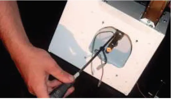
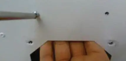
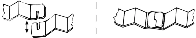
- Install turbulator strip(s) as required:
- Interlock turbulator strip sections.

- Slide connected sections into emitter tube(s) . Add further strips to form required length.

- Interlock turbulator strip sections.
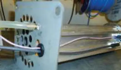
- Reinstall burner assembly and burner support casting :
- Run ignition, flame probe, and ground leads and pressure switch silicone tube through replacement gasket and reconnect leads and tube.
- Position burner support casting with replacement gasket and burner assembly so that wiring leads are not pinched and secure burner support casting to burner cabinet using four screws removed in step 4a.
- Re-install burner in emitter tube and tighten setscrew on burner support casting.
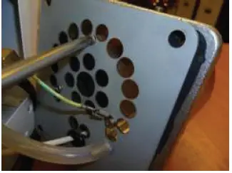
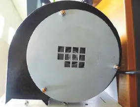
- Replace fan orifice plate (plates are stamped with PN):
Installation Location Elevation (Feet (Meters)) Unit Size Model VCS, VPS VCT, VPT Heater Tube Configuration (Fan Orifice Plate PN) US 0–2000 (0–610) 060 S20–40, U20–40 (269924) S20–40, U20–40 (269924) 080 S30–40, U20–40 (269925) S30–40, U40 (269925) 100 S30–50, U40 (269929) S30–40, U40 (269929) 125 S30–60, U40–60 (269931) S30–50, U40 (269931) 150 S40–70, U40–60 (269933) S40–60, U40–60 (269933) 170* S50–80, U60–80 (269933) — 170 S50–80, U60–80 (269937) S50–70, U60 (269937) 2001–5000 (611–1525) 060 S20, U20 (269925) S30–40, U40 (269924) S20, U20 (269925) S30–40, U40 (269924) 080 S30, U20 (269928) S40, U40 (269925) S30 (269928) S40, U40 (269925) 100 S30 (1011095) S40–50, U40 (269929) S30 (1011095) S40, U40 (269929) 125 S30–40 (269932) S50–60, U40–60 (269931) S30–40 (269932) S50, U40 (269931) 150 S40, U40 (269934) S50–70, U60 (269933) S40, U40 (269934) S50–60, U60 (269933) 170* S40, U40 (269934) S50–70, U60 (269933) — 5001–8000 (1526–2440) 060 S20, U20 (269928) S30–40, U40 (269925) S20, U20 (269928) S30–40, U40 (269925) 080 S30, U20 (269930) S40, U40 (269928) S30 (269930) S40, U40 (269928) 100 S30 (269933) S40–50, U40 (269932) S30 (269933) S40, U40 (269932) 125 S30–40 (269934) S50–60, U40–60 (269933) S30–40 (269934) S50, U40 (269933) 150 S50–70, U40, U60 (1011096) S50–60, U40, U60 (1011096) 170* S50–70, U40, U60 (1011096) — 8001–10,000 (2441–3045) 060 S20, U20 (269929) S30–40, U40 (269928) S20, U20 (269929) S30–40, U40 (269928) 080 S30, U20 (1011095) S40, U40 (269929) S30 (1011095) S40, U40 (269929) 100 S30 (269934) S40–50, U40 (269933) S30 (269934) S40, U40 (269933) 125 S30–40 (1011096) S50–60, U40–60 (269934) S30–40 (1011096) S50, U40 (269934) 150 S50–70, U40, U60 (1011096) S40, U40, U60 (1011096) 170* S50–70, U40, U60 (1011096) — Canada 0–2000 (0–610) 060 S20–40, U20–40 (269924) S20–40, U20–40 (269924) 080 S30–40, U20–40 (269925) S30–40, U40 (269925) 100 S30–50, U40 (269929) S30–40, U40 (269929) 125 S30–60, U40–60 (269931) S30–50, U40 (269931) 150 S40–70, U40–60 (269933) S40–60, U40–60 (269933) 170* S50–80, U60–80 (269933) S50–70, U60 (269937) 170 S60–80, U60–80 (269937 — 2001–4500 (611–1373) 060 S20, U20 (269925) S30–40, U40 (269924) S20, U20 (269925) S30–40, U40 (269924) 080 S30, U20 (269928) S40, U40 (269925) S30 (269928) S40, U40 (269925) 100 S30 (1011095) S40–50, U40 (269929) S30 (1011095) S40, U40 (269929) 125 S30–40 (269932) S50–60, U40–60 (269931) S30–40 (269932) S50, U40 (269931) 150 S40, U40 (269934) S50–70, U60 (269933) S40, U40 (269934) S50–60, U60 (269933) 170* S40, U40 (269934) S50–70, U60 (269933) — *Generation ZZ units. NOTE: If the tube configuration includes 5-foot tubes, the required fan orifice plate is for the next size downward (e.g., S35 requires an S30 plate, S55 requires an S50 plate, etc.).
- For model VCS, VCT, and VPT units:
- Remove and save four screws that secure top burner housing cover and remove cover to expose fan assembly.
- Remove and save four screws that secure fan assembly and remove fan assembly to access fan.
- For all models:
- For unit sizes 060–170, remove and save three nuts from fan studs.
 For unit size 200, remove and save four screws that secure existing fan orifice plate.
- Remove existing fan orifice plate and install replacement plate. Secure using existing fasteners.
- For unit sizes 060–170, remove and save three nuts from fan studs.
- For model VPS generation ZZ units, replace fan flange plate:
- Remove four screws that secure fan outlet and unplug from burner box.
- Remove and save two screws that secure fan flange plate with fan support bracket to burner housing and remove fan and bracket assembly.
- Remove and save remaining two screws and remove existing fan flange plate.
- Install self-adhesive fan flange plate gasket on underside of replacement fan flange plate.
- Position replacement fan flange plate onto burner housing and secure using existing screws.
- Position fan with fan support bracket on top of fan flange plate, ensuring that fan outlet is placed OUTSIDE flange, and secure using existing screws.
- Secure fan outlet to housing using four self-tapping screws from kit.
- For model VCS, VCT, and VPT units, re-install fan assembly and top burner housing cover using existing fasteners.
- For model VCS, VCT, and VPT units:
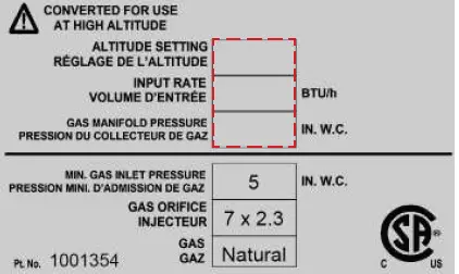
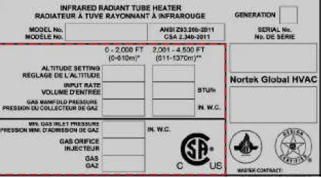
- Install conversion label:
- Using permanent marker, fill in data on conversion label for installation elevation, heat input, and gas manifold pressure.

- Adhere label to existing data label on unit.
 NOTE: When a generation ZZ burner is converted to propane, it becomes a generation BB burner. The burner label needs to be modified in permanent ink to indicate this.
Installation Location Elevation (Feet (Meters)) Model Burner Setting Unit Size 060 080 100 125 150 170 170* BTUh US 0–2000 (0–610) VCS, VPS — 60,000 80,000 100,000 125,000 150,000 169,000 150,000 VCT, VPT Low 48,000 60,000 75,000 95,000 100,000 125,000 — High 60,000 80,000 100,000 123,500 150,000 169,000 2001–3000 (611–915) VCS, VPS — 56,400 75,200 94,000 117,500 141,000 — 141,000 VCT, VPT Low 45,120 56,400 70,500 89,300 94,000 — High 56,400 75,200 94,000 116,090 141,000 3001–4000 (916–1220) VCS, VPS — 55,200 73,600 92,000 115,000 138,000 — 138,000 VCT, VPT Low 44,160 55,200 69,000 87,400 92,000 — High 55,200 73,600 92,000 113,620 138,000 4001–5000 (1221–1525) VCS, VPS — 54,000 72,000 90,000 112,500 135,000 — 135,000 VCT, VPT Low 43,200 54,000 67,500 85,500 90,000 — High 54,000 72,000 90,000 111,150 135,000 5001–6000 (1526–1830) VCS, VPS — 52,800 70,400 88,000 110,000 132,000 — 132,000 VCT, VPT Low 42,240 52,800 66,000 83,600 88,000 — High 52,800 70,400 88,000 108,680 132,000 6001–7000 (1831–2135) VCS, VPS — 51,600 68,800 86,000 107,500 129,000 — 129,000 VCT, VPT Low 41,280 51,600 64,500 81,700 86,000 — High 51,600 68,800 86,000 106,210 129,000 7001–8000 (2136–2440) VCS, VPS — 50,400 67,200 84,000 105,000 126,000 — 126,000 VCT, VPT Low 40,320 50,400 63,000 79,800 84,000 — High 50,400 67,200 84,000 103,740 126,000 8001–9000 (2441–2745) VCS, VPS — 49,200 65,600 82,000 102,500 123,000 — 123,000 VCT, VPT Low 39,360 49,200 61,500 71,250 82,000 — High 49,200 65,600 82,000 96,950 123,000 9001–10,000 (2746–3045) VCS, VPS — 48,000 64,000 80,000 100,000 120,000 — 120,000 VCT, VPT Low 38,400 48,000 60,000 69,350 80,000 — High 48,000 64,000 80,000 94,480 120,000 Canada 0–2000 (0–610) VCS, VPS — 60,000 80,000 100,000 125,000 150,000 169,000 150,000 VCT, VPT Low 48,000 60,000 75,000 95,000 100,000 125,000 — High 60,000 80,000 100,000 123,500 150,000 169,000 2001–4500 (611–1373) VCS, VPS — 54,000 72,000 90,000 112,500 135,000 — 135,000 VCT, VPT Low 43,200 54,000 67,500 85,500 90,000 — High 54,000 72,000 90,000 112,500 135,000 *Generation ZZ units.
- Using permanent marker, fill in data on conversion label for installation elevation, heat input, and gas manifold pressure.
- For models VCS, VCT, and VPT with ducted combustion air, connect flexible hose to fresh air inlet on side of burner cabinet and secure using hose clamp.
- Reconnect gas supply at union outside of cabinet and leak test connection using leak detecting solution. If leak is detected, tighten connection. If leak cannot be stopped by tightening connection, replace part(s).
- Turn ON electric and gas.
- Check for proper operation.
 Gas Manifold Pressure for Propane Units
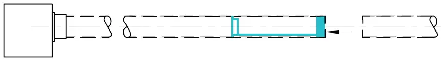
 For unit size 200, remove and save four screws that secure existing fan orifice plate.
 NOTE: When a generation ZZ burner is converted to propane, it becomes a generation BB burner. The burner label needs to be modified in permanent ink to indicate this.
Specifications and illustrations subject to change without notice or incurring obligations. Latest version of this manual is available at www.reznorhvac.com.
©2023 Nortek Global HVAC LLC, O’Fallon, MO. All rights reserved.
VCS-VCT-VPS-VPT-DL2 (05-23) 1042554-A


