REZNOR CD2 Downturn Nozzle Kit For Gas Fired Unit Heaters
DANGER
Before installing a downturn nozzle, ensure that the unit is installed using four-point suspension in accordance with the installation manual provided with the unit.
- Refer to the installation manual provided with the heater for important safety information.
- Downturn nozzles are designed to direct the discharge air in a more vertical flow. Ensure that the unit location provides sufficient clearance for the nozzle option that is being installed. Refer to Table 1 for option descriptions.
| Table 1. Downturn Nozzle Options | |||
| Option | Description | Option | Description |
| CD2 | Downturn of from 25- to 65-degrees | CD4 | CD2 nozzle with vertical louvers (option CD1) |
| CD3 | Downturn of from 50- to 90-degrees | CD5* | CD3 nozzle with vertical louvers (option CD1) |
| *Option CD5 is available only on model UBX and UBZ units. | |||
KIT COMPONENTS
Ensure that all components listed in Table 2 or Table 3 are available before beginning installation.
| Table 2. Kit Components—Models UBX, UBZ, UDX, and UDZ | ||||||||
| Component | Option | Model | Unit Size | |||||
| 030, 045 | 060, 075 | 100, 125 | 150, 175, 200 | 225, 250 | 300, 350, 400 | |||
| PN (Quantity)* | ||||||||
| Kit package | CD2 | All | 1036261 | 1036262 | 1036263 | 1036264 | 1036265 | 1036266 |
| UBZ, UDZ** | 1036267 | 1036268 | 1036269 | 1036270 | 1036271 | 1036272 | ||
| CD3 | All | 1036273 | 1036274 | 1036275 | 1036276 | 1036277 | 1036278 | |
| UBZ, UDZ** | 1036279 | 1036280 | 1036281 | 1036282 | 1036283 | 1036284 | ||
| CD4 | All | 1036285 | 1036286 | 1036287 | 1036288 | 1036289 | 1036290 | |
| UBZ, UDZ** | 1036291 | 1036292 | 1036293 | 1036294 | 1036295 | 1036296 | ||
| CD5 | UBX, UBZ | 1036306 | 1036307 | 1036308 | 1036309 | 1036310 | 1036311 | |
| UBZ** | 1036312 | 1036313 | 1036314 | 1036315 | 1036316 | 1036317 | ||
| Right nozzle panel | CD2, CD4 | All | 1033918 | 1034681 | 1034682 | 1034683 | 1034684 | 1034685 |
| CD3, CD5 | 1033918 (2) | 1034681 (2) | 1034682 (2) | 1034683 (2) | 1034684 (2) | 1034685 (2) | ||
| Left nozzle panel | CD2, CD4 | All | 1033917 | 1034676 | 1034677 | 1034678 | 1034679 | 1034680 |
| CD3, CD5 | 1033917 (2) | 1034676 (2) | 1034677 (2) | 1034678 (2) | 1034679 (2) | 1034680 (2) | ||
| Top nozzle panel | CD2, CD4 | All | 1033919 | 1034671 | 1034672 | 1034673 | 1034674 | 1034675 |
| CD3, CD5 | 1033919 (2) | 1034671 (2) | 1034672 (2) | 1034673 (2) | 1034674 (2) | 1034675 (2) | ||
| Nozzle bottom | CD2, CD4 | All | 1033921 | 1033921 | 1033921 | 1034669 | 1034669 | 1034670 |
| CD3, CD5 | 1033921 (2) | 1033921 (2) | 1033921 (2) | 1034669 (2) | 1034669 (2) | 1034670 (2) | ||
| Nozzle blockoff | CD2, CD3, CD4, CD5 | All | 1036215 | 1034686 | 1036205 | 1036206 | 1036207 | 1036208 |
| UBZ, UDZ** | 1036209 | 1036210 | 1036211 | 1036212 | 1036213 | 1036214 | ||
| Blockoff panel | CD3, CD5 | All | 1033920 | 1036216 | 1036217 | 1036218 | 1036219 | 1036220 |
| Louver frame | CD4, CD5 | All | 1028413 | 1028433 | 1028443 | 1033695 | 1033715 | 1033728 |
| Vertical louver | 1028418 (5) | 1028434 (5) | 1028441 (5) | 1033904 (8) | 1033961 (8) | 1033730 (8) | ||
| Louver spring | 195046 (5) | 195046 (5) | 195046 (5) | 195046 (8) | 195046 (8) | 195046 (8) | ||
| Screw, sheet metal, 8-18 × 3/8 | 195638 (AR) | |||||||
| *Quantity is one (1) unless otherwise indicated. AR = as required. | ||||||||
| **For model UBZ or UDZ units manufactured before 8 NOV 2022. | ||||||||
DO NOT DESTROY. PLEASE READ CAREFULLY. KEEP IN A SAFE PLACE FOR FUTURE REFERENCE.
| Table 3. Kit Components—Model UEZ | ||||||
| Component | Option | Unit Size | ||||
| 055 | 085 | 110 | 130, 180 | 260, 310 | ||
| PN (Quantity)* | ||||||
| Kit package | CD2 | 1041269 | 1041272 | 1041275 | 1042599 | 1042600 |
| CD3 | 1041270 | 1041273 | 1041276 | 1042601 | 1042602 | |
| CD4 | 1041271 | 1041274 | 1041277 | 1036297 | 1042603 | |
| Right nozzle panel | CD2, CD4 | 1036677 | 1036683 | 1036689 | 1042328 | 1042333 |
| CD3 | 1036677 (2) | 1036683 (2) | 1036689 (2) | 1042328 (2) | 1042333 (2) | |
| Left nozzle panel | CD2, CD4 | 1036676 | 1036682 | 1036688 | 1042327 | 1042332 |
| CD3 | 1036676 (2) | 1036682 (2) | 1036688 (2) | 1042327 (2) | 1042332 (2) | |
| Top nozzle panel | CD2, CD4 | 1036675 | 1036681 | 1036687 | 1042325 | 1042330 |
| CD3 | 1036675 (2) | 1036681 (2) | 1036687 (2) | 1042325 (2) | 1042330 (2) | |
| Nozzle bottom | CD2, CD4 | 1036678 | 1036684 | 1036690 | 1042324 | 1042329 |
| CD3 | 1036678 (2) | 1036684 (2) | 1036690 (2) | 1042324 (2) | 1042329 (2) | |
| Nozzle blockoff | CD2, CD3, CD4 | 1036680 | 1036686 | 1036692 | 1042326 | 1042331 |
| Blockoff panel | CD3 | 1036679 | 1036685 | 1036691 | 1042597 | 1042598 |
| Louver frame | CD4 | 1036666 | 1036668 | 1036670 | 1033902 | 1033728 |
| Vertical louver | 1036667 (6) | 1036669 (6) | 1036671 (7) | 1033904 (8) | 1033730 (8) | |
| Louver spring | 195046 (6) | 195046 (6) | 195046 (7) | 195046 (8) | 195046 (8) | |
| Screw, sheet metal, 8-18 × 3/8 | 195638 (AR) | |||||
| *Quantity is one (1) unless otherwise indicated. AR = as required. | ||||||
INSTALLATION
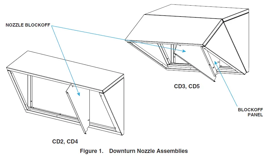
- Assemble top and side panels of downturn nozzle assembly (see Figure 1):
- a. Secure right and left panels to top panel using screws from kit. Ensure that panel with slotted holes in bottom of panel is installed on door side of unit. Nozzle bottom will be added in step 7.
- b. If installing option CD3 or CD5, assemble second nozzle section—sections will be joined in step 6.

- If heater is already installed, turn OFF gas and electric power. Allow time for louvers to cool before proceeding.
- Remove access door:
- a. Loosen screwlock and open door.
- b. Disconnect door strap and remove door.
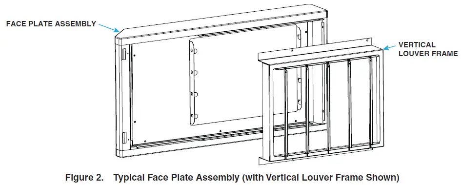
- Remove face plate assembly (see Figure 2):
- a. Remove and save two screws next to access door slots from back of face plate.
- b. To access remaining screws that secure face plate, remove each horizontal louver. Push louver toward spring to compress spring and release louver. Remove and save each louver and spring.
- c. Remove and save screws that secure face plate to unit and remove face plate assembly.

- If installing option CD4 or CD5, position vertical louver frame (see Figure 2) in face plate outlet so that holes align and secure frame to face plate using screws from kit.
- If installing option CD3 or CD5, position second assembled nozzle section in outlet of nozzle already installed. Secure second nozzle section to first nozzle section using screws from kit to create downturn with two sections (see Figure 1).
- Mount downturn nozzle assembly to face plate assembly:
- a. Position top and side panels assembled in step 1 on back of face plate assembly so that holes align and secure top panel using screws from kit. Do not install screws in side panels at this point.
- b. Slide nozzle bottom (see Figure 1) into place so that it rests on small tabs on each side. Align holes and secure nozzle bottom to face plate using screws from kit.
- c. Align holes and secure side panels to face plate using screws from kit.
- Install downturn nozzle assembly with face plate assembly:
- a. Position downturn nozzle assembly with face plate assembly so that holes align and secure nozzle to front of unit using existing screws.
- b. Position nozzle blockoff (see Figure 1) so that holes align and secure to face plate using screws from kit.
- c. If installing option CD3 or CD5, secure blockoff panel (see Figure 1) to nozzle blockoff.
- d. Re-install existing two screws in back of face plate next to slots for access door.
- Re-install access door:
- a. Place door tabs in slots and reconnect door strap.
- b. Close door and tighten screwlock.
NOTE: Before installing the louvers, note the louver curve and determine how the louvers should be positioned to provide the optimal throw pattern. Depending on where the heater is installed and on the desired airflow direction, the louvers may be installed with their curves all in the same direction (either way) or the right half one way and the left the other.
- Install and adjust louvers:
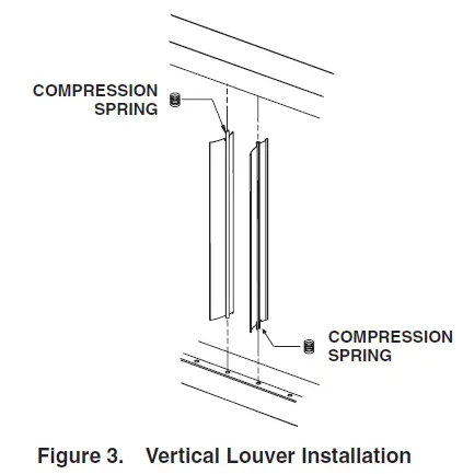
- a. If installing option CD4 or CD5, install vertical louvers in louver frame:
- On notched end of louver, slide louver spring over tab.
- With wider louver blade facing in toward heat exchanger, push tab with louver spring into hole in top or bottom louver frame (see Figure 3)—spring compresses. Insert tab on other end of louver into opposite louver frame. For left airflow, compress spring into top louver frame. For right airflow, compress spring into bottom louver frame.

- Install all remaining louvers in accordance with steps 10a(1) and 10a(2).
- b. Re-install horizontal louvers and springs.
- c. Adjust all louvers to provide desired throw pattern.
- a. If installing option CD4 or CD5, install vertical louvers in louver frame:
- Turn ON gas and electric power.
- Light heater in accordance with lighting instructions.
- Check for proper operation.
Specifications and illustrations subject to change without notice or incurring obligations. Latest version of this manual is available at www.reznorhvac.com.
©2023 Nortek Global HVAC LLC, O’Fallon, MO. All rights reserved.
UBX-UBZ-UDX-UDZ-UEZ-CD2,3,4,5 (03-23) 1036421-B