
REZNOR APD Relay Kit
RELAY KIT INSTALLATION FOR MULTIPLE HEATER CONTROL
- OPTIONS CL31 AND CL32 FOR MODELS APD, F, B, UDAP, UDAS, UDBP, UDBS, UEAS, AND VR
- DO NOT use these multiple heater control options with a two-stage gas valve or a two-stage thermostat.
- These instructions are designed to assist a qualified electrician in installing this multiple heater control kit.
- All electrical wiring and connections, including electrical grounding, MUST be in accordance with the National Electric Code ANSI/NFPA No. 70 (latest edition) or, in Canada, with the Canadian Electrical Code, Part 1, CSA Standard C22.1. In addition, the installation must comply with local ordinances and applicable gas company requirements.
- These relay kits are designed to permit the control of up to five heaters (one control unit and up to four additional non-control units) with one single-stage thermostat or with a time clock and single or multiple single-stage thermostats. For maximum safety, the multiple control is installed in the low voltage circuit. Interruption of the supply voltage is not recommended.
- Refer to the installation manual provided with the heater for important safety information.
- Pay attention to all dangers, warnings, cautions, and notes highlighted in this manual. Safety markings should not be ignored and are used frequently throughout to designate a degree or level of seriousness.
- Model/option/voltage applicability is listed in Table 1.
| Table 1. Model/Voltage/Option Applicability | ||||
| Model | Voltage/Phase | Option for Control Unit | Option for Non-Control Unit(s) | No. of Non-Control Units Permitted |
| APD, UDAP, UDAS, UDBP, UDBS | 115/1, 208/1, 230/1, 208/3, 230/3, 460/3, 575/3 | CL31 |
CL32 |
4 |
| F. B, VR | 115/1 | CL31 | ||
| 208/1, 230/1, 208/3, 230/3, 460/3 | CL32 | |||
| 575/3 | CL31 | |||
| UEAS | 115/1 | CL31 | ||
| *Except as follows: unit size 400 can have five (5) additional non-control units, unit size 800 can have three (3) additional non-control units, and unit size 1200 can have two (2) additional non-control units. | ||||
COMPONENTS
Ensure that all components listed in Table 2 are available before beginning installation.
| Table 2. Relay Kit Components | ||||
| Item No.* | Component | Description | Option** | |
| CL31 | CL32 | |||
| PN (Quantity) | ||||
| APD, UDAP, UDAS, and UEAS Models | ||||
| — | Option package PN | 197155 (1) | 197156 (1) | |
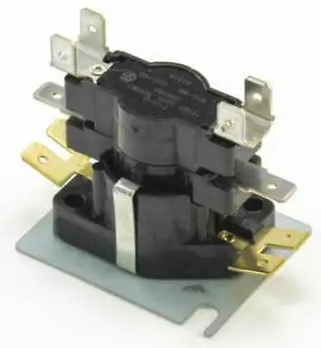
| 1 | Relay assembly | Includes relay and specially-designed bracket | 197157 (2) | 197157 (1) |
| 1A | Relay | Wired and mounted on bracket | 18549 (2) | 18549 (1) |
| 2 | Screw | Self-drilling, for securing relay bracket | 195249 (2) | 195249 (1) |
| 3 | Cable clamp | 3/16 | 16228 (2) | 16228 (1) |
| 4 | Label | Wiring diagram | 197164 (2) | 197164 (1) |
| 5 | Transformer | 40VA | 194808 (1) | — |
| 6 | Wiring harness assembly | Brown wires | 197160 (1) | — |
| *See Figure 1 and Figure 2. | ||||
| **Option CL31 includes components for one control unit and one additional unit. Option CL32 includes components for each additional non- control unit with the following exception: for 208V, 230V, and 460V F, B, and VR models, option CL32 is used for the control unit and each additional non-control unit (refer to Table 1). | ||||
COMPONENTS—CONTINUED
| Table 2. Relay Kit Components—Continued | ||||
| Item No.* | Component | Description | Option** | |
| CL31 | CL32 | |||
| PN (Quantity) | ||||
| UDBP and UDBS Models | ||||
| — | Option package PN | 202958 (2) | 197156 (1) | |
| 1 | Relay assembly | Includes relay and specially-designed bracket | 197157 (2) | 197157 (1) |
| 1A | Relay | Wired and mounted on bracket | 18549 (2) | 18549 (1) |
| 2 | Screw | Self-drilling, for securing relay bracket | 195249 (2) | 195249 (1) |
| 3 | Cable clamp | 3/16 | 16228 (2) | 16228 (1) |
| 4 | Label | Wiring diagram | 197164 (2) | 197164 (1) |
| F and B Models | ||||
| — | Option package PN | 102248 (1) | 102249 (1) | |
| 1 | Relay assembly | Includes relay and specially-designed bracket | 102243 (2) | 102243 (1) |
| 1A | Relay | Wired and mounted on bracket | 18549 (2) | 18549 (1) |
| 2 | Screw | Sheet metal, #6 × 1-1/2, for transformer | 103152 (2) | — |
| 2A | Tinnerman clip | #C1110-62, for transformer screws | 111233 (2) | |
| 3 | Cable clamp | 3/16 | 16228 (2) | 16228 (1) |
| 4 | Label | Wiring diagram | 131127 (2) | 131127 (1) |
| 5 | Transformer | 35VA | 102708 (1) | — |
| VR Models | ||||
| — | Option package PN | 205685 (1) | 205686 (1) | |
| 1 | Relay assembly | Includes relay and specially-designed bracket | 102243 (2) | 102243 (1) |
| 1A | Relay | Wired and mounted on bracket | 18549 (2) | 18549 (1) |
| 2 | Screw | #8 × 1 | 121033 (4) | 121033 (2) |
| 2A | Spacer | 98872 (4) | 98872 (2) | |
| 3 | Cable clamp | 3/16 | 16228 (2) | 16228 (1) |
| 4 | Label | Wiring diagram | 197164 (2) | 197164 (1) |
| 5 | Transformer | 40VA | 194808 (1) | — |
| 5A | Wire connector | Twist-on, orange | 16354 (1) | |
| *See Figure 1 and Figure 2. | ||||
| **Option CL31 includes components for one control unit and one additional unit. Option CL32 includes components for each additional non- control unit with the following exception: for 208V, 230V, and 460V F, B, and VR models, option CL32 is used for the control unit and each additional non-control unit (refer to Table 1). | ||||
INSTALLATION
Install the relay kit as follows. Item numbers refer to Table 2.
- Turn OFF gas and electric power.
- Replace transformer on control unit (all models except UDBP and UDBS):
- Remove or open panel(s) as necessary and locate factory-installed transformer (see Figure 1).
- For models APD, UDAP, UDAS, and UEAS, transformer is mounted on control board at bottom of control compartment.
- For models F and B, remove left (when facing rear of heater) outer side panel to expose inner side panel and wiring.
- For model VR, open control side only.
- Mark and disconnect transformer wires and remove existing transformer.
- Install replacement transformer:
- For models APD, UDAP, UDAS, UEAS, and VR, secure transformer (5) using same screws.
- For models F and B, slide Tinnerman clips (2A) over transformer (5) and secure transformer using screws
- from kit.
- Reconnect transformer wires.
- Install or close panel(s) as necessary.

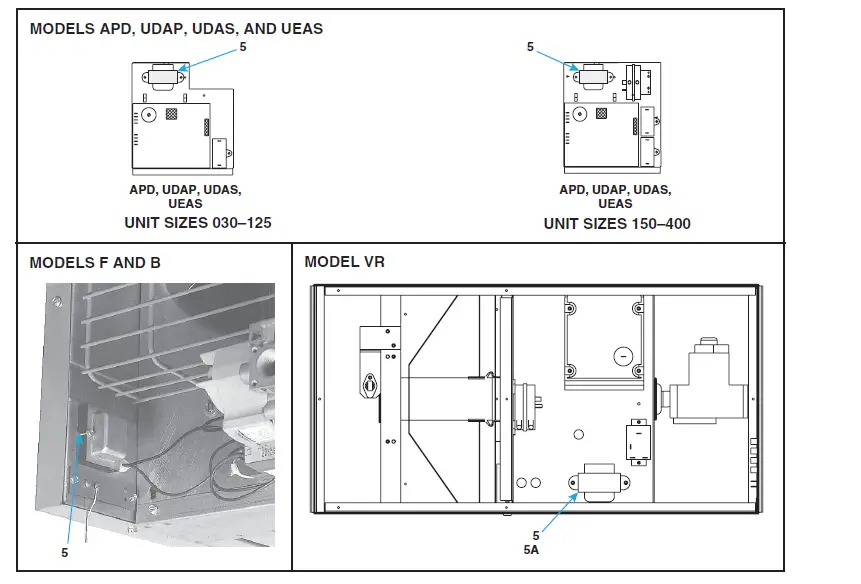
Figure 1. Transformer Replacement (Refer to Table 2)
- Install relay assembly on control unit and on all non-control units (see Figure 2):
- For models APD, APD, UDAP, UDAS, UDBP, UDBS, and UEAS:
- At rear of heater, remove screws from edge of cabinet bottom.
- Secure relay assembly (1 and 1A) and cable clamp (3) as shown using existing screws for unit sizes 030–125 or one existing screw and one screw (2) from kit for unit sizes 150–400 and all UEAS models.
- For models F and B:
- At rear of heater, remove thermostat terminal strip screws and remove terminal strip.
- Slide relay assembly (1 and 1A) bracket underneath thermostat terminal strip and secure bracket, terminal strip, and cable clamp (3) as shown using existing screws.
- Secure blue and brown wires in cable clamp (3).
- For model VR:
- At end of burner/control box, remove thermostat terminal strip screws and remove terminal strip.
- Secure terminal strip, relay assembly (1 and 1A), and cable clamp (3) as shown using screws (2) and spacers (2A).
- Secure blue and brown wires in cable clamp (3).
Be careful not to short thermostat leads to a metal surface. Doing so will cause the transformer to fail and require replacement.
INSTALLATION—CONTINUED
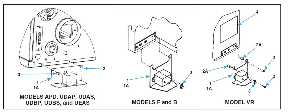
Figure 2. Relay Installation (Refer to Table 2)
NOTE: VR models do not have a W2 terminal. Splice between the DSI control COM and 24V on the transformer and use the twist-on wire connector (5A) to connect the wires.
- Connect relay (1A) to TEW-type control wiring in accordance with model-specific wiring diagram label (4) from kit. Do not exceed length and distance listed in Table 3.
| Table 3. Control Wiring Specifications | ||
| Gauge | Maximum Length (Feet (Meters))* | Maximum Distance (Feet (Meters)) |
| 12 | 2100 (640) | 1050 (320) |
| 14 | 1300 (457) | 650 (198) |
| 18 | 500 (152) | 250 (76) |
| *For complete circuit. | ||
- Install wiring diagram label:
- For future reference, check appropriate box for heater function—PRIMARY HEATER for control unit or SECONDARY HEATER for non-control unit—on wiring diagram label (4).
- Locate required wiring diagram label position on unit:
- For models APD, APD, UDAP, UDAS, UDBP, UDBS, and UEAS, label location is bottom rear corner of access panel.
- For models F and B, label location is lower right corner of outer left (when facing rear of heater) side panel.
- For model VR, label location is rear of burner box above terminal strip.
- Wipe surface with clean, dry cloth.
- Remove label backing and adhere label to unit.
- Restore system to service:
- Turn ON gas and electric power.
- Light heater in accordance with lighting instructions.
- Check for proper operation.
Specifications and illustrations subject to change without notice or incurring obligations. Latest version of this manual is available at www.reznorhvac.com.
©2022 Nortek Global HVAC LLC, O’Fallon, MO. All rights reserved.
OPT-CL31-CL32 (04-22) 102247-B