
![]() 259521 CP-Relay Kit
259521 CP-Relay Kit
Instructions
Revision: OPT-RELAY (06-22) 259524-A
Supersedes: CP-Relay Kit 259521 (09-17) PN259524R2
259521 CP-Relay Kit
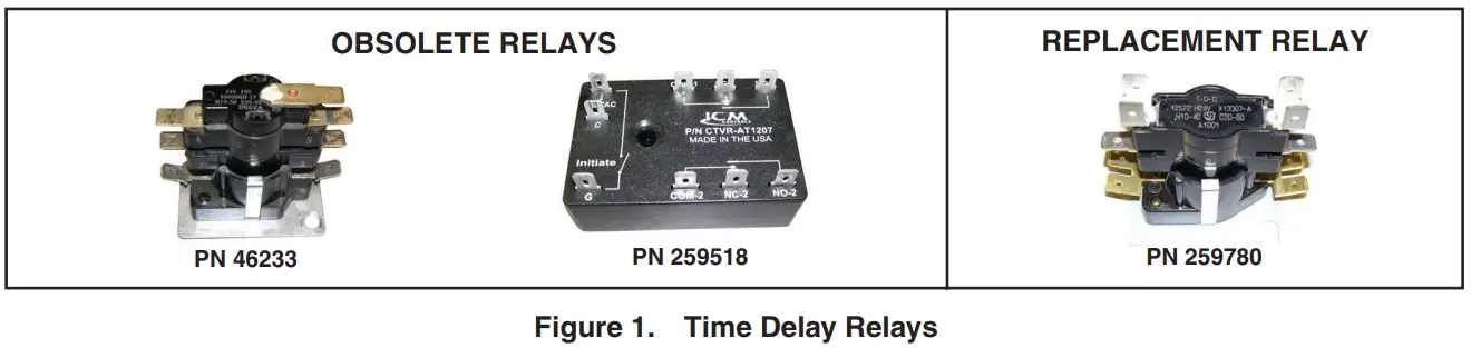
RELAY REPLACEMENT KIT (PN 259521) INSTALLATION
ALL POWER-VENTED UNITS WITH TIME DELAY RELAY PN 46233 OR 259518![]() WARNING
WARNING ![]()
Turn OFF the gas supply and then disconnect the electric power before performing service work.
- This kit is designed to replace either the Texas Instruments (#60000GO-17) time delay relay (PN 46233) or the ICM (#CTVR-AT1207) time delay relay (PN 259518) on any Reznor unit.
- This application includes but is not limited to models SC(A)(B)(E), SSCBL, RPV, RP(B)BL), HRPD, PGBL, PCCA, and AHCA and also applies to gravity-vented models F and B when equipped with an optional power venter.
- Refer to the installation manual provided with the unit for important safety information.
- Relay replacement kit PN 259521 includes these instructions and the Thermotic (#12S22 305587) replacement time delay relay (PN 259780).

INSTALLATION
- Turn OFF gas and disconnect electric power.
- Remove venter junction box cover.
- Mark and disconnect existing time delay relay wires.
- Remove hardware that secures existing time delay relay in venter junction box and remove relay.
- Use replacement time delay relay as template to mark and drill hole(s) in venter junction box as required. Secure replacement relay in junction box using field-supplied hardware.
- Reconnect wires to replacement time delay relay:
a. For ALL Reznor units EXCEPT model F and B units WITH power venter, wiring is same as for relay being replaced.
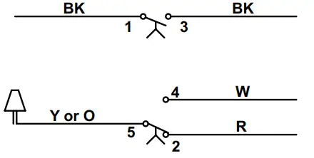
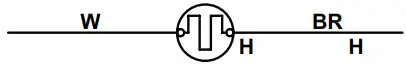
b. For model F and B units WITH power venter, wiring depends on relay being replaced. Connect wires in accordance with appropriate wiring diagram shown in Figure 2.WIRING FOR OBSOLETE RELAY PN 46233 WIRING FOR REPLACEMENT RELAY PN 259780 VENTER TIME DELAY RELAY CONTACTS VENTER TIME DELAY RELAY CONTACTS 

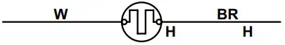
VENTER TIME DELAY RELAY HEATER VENTER TIME DELAY RELAY HEATER 

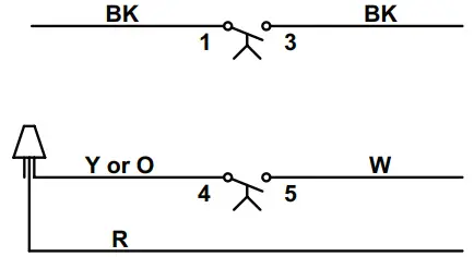
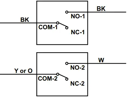
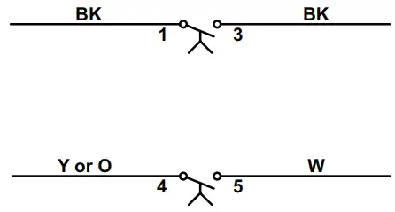
WIRING FOR OBSOLETE RELAY PN 259518 WIRING FOR REPLACEMENT RELAY PN 259780 VENTER TIME DELAY RELAY CONTACTS VENTER TIME DELAY RELAY CONTACTS 

VENTER TIME DELAY RELAY HEATER VENTER TIME DELAY RELAY HEATER  * REMOVE THIS WIRE.
Figure 2. Wiring Connections for Model F or B Unit with Power Venter
- Replace venter junction box cover.
- Turn ON electric and gas and check unit for proper operation.
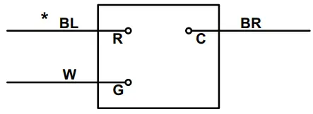 * REMOVE THIS WIRE.
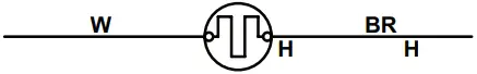
Specifications and illustrations subject to change without notice or incurring obligations.
Latest version of this manual is available at www.reznorhvac.com.
©2022 Nortek Global HVAC LLC, O’Fallon, MO. All rights reserved.
OPT-RELAY (06-22) 259524-A