![]()
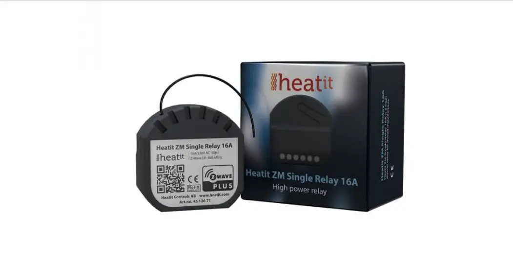
HEATIT
ZM SINGLE
RELAY 16A
Installers manual
![]()
Firmware 1.0
01.12.2020
Ver 2020-B
INTRODUCTION
Heat ZM Single Relay is a high-power relay for inwall installations.
The relay allows you to control connected devices either through your Z-Wave network or via a wired switch. The module is equipped with a 16A relay and has scene controller functionality. The device can withstand a load of max 16A /3600W at 230VAC.
STATEMENT REGARDING PRODUCTS FROM MULTIPLE
MANUFACTURERS
Please read this before installation
This device may be used with all devices certified with the Z-Wave Plus™ certificate and should be compatible with such devices produced by any manufacturer. Every primary controller is different depending on the manufacturer, their target audience and intended use/application. Please review the functionalities implemented by the primary controller you intend to use with our Z-Wave Plus certified device to ensure that it provides the necessary controls to take full advantage of our product’s capabilities.
BEHAVIOR WITHIN THE Z-WAVE™ NETWORK
This device may be operated within any Z-Wave network with Z-Wave-certified devices from other manufacturers. All non-battery-operated nodes within the network will act as repeaters regardless of the manufacturer to increase the reliability of the network. On delivery, the device does not belong to any Z-Wave network. The device needs to be added to an existing network to communicate with the other devices within it. Devices may also be removed from a network. The add/remove processes are initiated by the primary controller of the Z-Wave network.
QUICKSTART
- Switch off the mains supply (disable the fuse).
- Open the wall switch box.
- Connect wires according to the labeling described in Chapter 5 ”Installation”.
- After verifying the connections, switch the main supply back on.
- Set the primary controller in add mode (security/non-security).
- Press the configuration button or switch connected to S1 x 3 times in rapid succession.
- The device LED will blink in green when adding procedure has been successfully initiated. When the device is included in the home automation system, the LED will light up in green for 1 second. If the device is unsuccessfully added, the LED will light up in RED for 1 second. For more information, please see Chapter 7 ”Add/ Remove”.
- Change the value of Parameter 11 to 10% of your connected load.
INSTALLATION
Installation must be done by a qualified electrician in accordance with the National Building codes. Before installation, disconnect any power to the device mains. During the installation of the device, power to the device must be disconnected AT ALL TIMES! The product allows for wiring of cables with a cross-section of 1×2.5mm2. The product can be wired to both a Single Wall Switch and a Double Wall Switch as illustrated in the following figure:
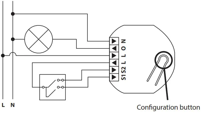
N Power connection (Neutral) 230VAC.
O Output. The load needs to be connected between O and Neutral.
L Power connection (Live) 230VAC.
L Power connection (Live) 230VAC.
S2 Switch 2 is used as a scene controller.
NB! In toggle mode, S2 must not be connected.
S1 Switch 1. Used to control the internal relay.
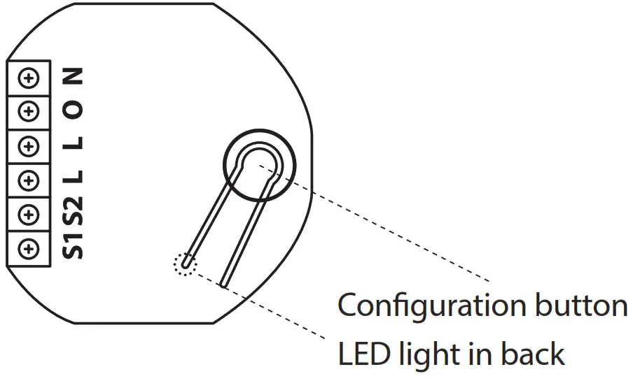
CONTROL
The device features a configuration button and an LED indicator.
ADD/REMOVE
Please read this before installation
The primary controller/gateway has a mode for adding or removing devices. Please refer to your primary controller manual on how to set the primary controller in add/remove mode. The device may only be added or removed from the network if the primary controller is in add/ remove mode.
When the device is removed from the network, it will NOT revert to factory settings.
There are two ways to add the device to a Z-Wave network.
7.1 Method 1: Standard (Manual)
Add/remove mode is indicated on the device by a blinking green LED.
This lasts until a timeout occurs after 90 seconds, or until the module has been added to/removed from the network.
The LED will light up for 3 seconds if adding/removing is successful.
The device is now ready for use with default settings.
If adding/removing fails, the LED will light up in red for 3 seconds.
NB! When the device is removed from the gateway, the parameters are not reset. To reset the parameters, see Chapter 8 ”Factory reset”.
If inclusion fails, please perform a ”remove device” process and try again.
If the LED lights up in red again, please see Chapter 8 “Factory reset”.
7.2 Method 2: SmartStart (Automatic)
SmartStart enabled products may be added to a Z-Wave network by scanning the Z-Wave QR-Code on the product if your primary controller supports SmartStart inclusion. No further action is required and the SmartStart product will be added automatically after being powered on within range of the primary controller.
FACTORY RESET
Press and hold the configuration button. After 3 seconds the LED will start to blink in green. After 20 seconds the LED will stop blinking and emit a constant light. You may now release the button.
NB! Please use this procedure only when the primary controller/ gateway is missing or otherwise inoperable.
STARTUP
After powering up the device for the first time, all the parameters will have default settings.
SAFETY FEATURES
The device security features make the device safe to use and notify the user of any unexpected behavior in the device, such as overload or overheating. If this happens, the relay cuts power to prevent failure.
Heat ZM Single Relay 16A has the following features: 10.1 Overload
The device features a default 16A overload protection. The default overload is triggered if there is a power draw of more than16Amps for longer than 2 seconds, or 0.2 seconds if the measured load is more than 20A. When a current higher than 16Amps has been detected, the connected load must be checked. It is not possible to turn the relay back on until a power cycle has been performed. This prevents unwanted power cuts that may be caused by inrush currents. The user may define a specific user cutoff according to need using Parameter 1.
When an overload is detected, the device will:
- Set the relay in OFF-state when triggered and send a binary switch report representing relay state
- Send Notification (Overload detected)
To clear the overload state, the relay must be switched back on manually using Z-Wave or a connected switch. When the realy state has been changed and overload is no longer triggered, the device will send a Notification (Overload idle). Parameter 2 can be set to automatically retry at regular intervals. This Parameter 2 setting will only work if the overload was triggered by a user-specific load limit (Parameter 1).
10.2 Overheating
The device features an internal temperature sensor that prevents any overheating caused by external high loads.
When overheating is detected, the device will:
- Set the relay in OFF-state when triggered and send a binary switch report representing relay state
- Send Notification (Overheating detected)
To clear the overheating state, the relay must be switched back on manually using Z-Wave or a connected switch. When the relay state has been changed and the temperature stabilized, the device will send a Notification (Overheating idle). Parameter 2 can be set to automatically retry at regular intervals.
SWITCH MODE
The device supports two types of switches, momentary and toggle switches. The device uses momentary switches by default.
11.1 Momentary Switch (NO) – Default
This is the recommended mode that allows for the use of all features.
When used as a momentary switch, the device supports the HOLD and RELEASE functions for central scene and association groups.
The switch must be a normally open switch.
11.2 Toggle Switch (ON/OFF)
In toggle mode, the device relay and switch state will not always be equal as the user can control using other Z-Wave devices.
When using the device in toggle switch mode, the device will lose the following functionality:
- Inclusion using S1
- Scene Controller Commands
- Association Group 3 and 5, Multilevel Switch (level increase/decrease)
The toggle switch will not always turn ON when the output of the switch is HIGH because the relay may also be controlled externally using the Z-Wave protocol.
NB! When using toggle switch, S2 must not be connected in order to ensure correct functionality.
12. LED BLINKING PATTERNS DESCRIPTION
The device support numerous LED blinking patterns to make it as easy as possible to identify the issue.
| Device Not in Network The LED will flash in red when the the device is not added to a Z-Wave network | 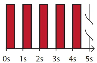 |
| Device Status On: Green for 1 sec Off: Red for 1 sec (when LED’s are enabled) | 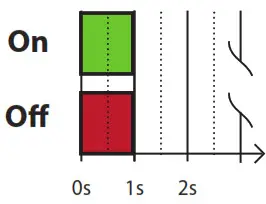 |
| Add/Remove When device enters add/remove mode the LED will flash green. If successful, the LED will light up in green for 3 seconds. If unsuccessful, the LED will light up in red for 3 seconds. |  |
| Factory Reset If the button is pressed for more than 3 seconds, the GREEN LED will start flashing. When the button has been pressed for 20 seconds, the GREEN LED will light up for 3 seconds. | |
| Figure 1 (success) Within the 3 second period, the button must be released. If the the button is released within this period, the device will reset and start flashing because it is not included in a gateway. | 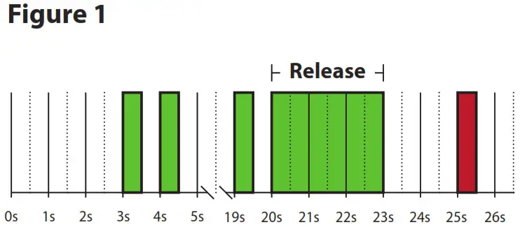 |
| Figure 2 (fail) If the button is released before the 3 second period, the device will indicate fail by turning RED LED on for 3 seconds. | 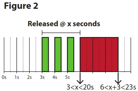 |
| Figure 3 (fail) The button MUST be released between 20 and 23 seconds for the local reset to take place. If held longer, the device will ignore the command. | 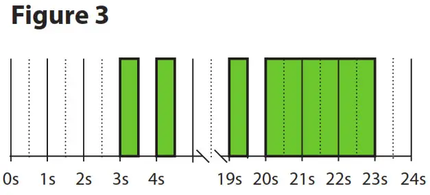 |
13. QR-CODE PLACEMENT (DSK)
The QR-Code is needed when including a device using S2 security or SmartStart. The DSK can be found in the QR-Code and is located;
- On the product.
- On the Quick Guide manual.
- On the product box.
SECURITY
S2 security enhances Z-Wave Plus with an additional layer of AES 128-bit encryption of the wireless Z-Wave communication to prevent hacking and man-in-middle attacks on the home network. This device supports S2 and has a Z-Wave DSK QR-Code label that may be used when the module is added to the Z-Wave home network. The primary
controller will ask for a 5-digit code, which can be found underneath the QR-Code. The primary controller will then ask you to confirm the rest of the code that is contained in the QR-Code.
NODE INFORMATION FRAME
The node information frame is the ”business card” of a Z-Wave device.
It contains information about the device type and its technical features.
The add and remove procedure of the device is confirmed by sending out a node information frame. Besides this, it may be necessary for certain network operations to send out a node information frame.
ASSOCIATIONS
Z-Wave devices interact with other Z-Wave devices. The relationship between one device controlling another device is called an association.
In order to control a subordinate device, the controlling device needs to maintain a list of devices that will receive controlling commands. These lists are called ”Association Groups”. They are always related to the specific event triggered (e.g., sensor reports). In case the event is triggered, all devices stored in the respective association group will
receive a joint wireless command.
16.1 Setting and removing associations
Associations may be assigned and removed via Z-Wave commands. Please refer to your primary controller/Z-Wave gateway for more information.
16.2 Association Groups
| RELAY DEVICE | THE MAIN DEVICE |
| Group 1 Lifeline | Lifeline. (Normally used by the Z-Wave Controller) Sends: – Device Reset Notifications. – Indicator Report – Configuration Report – Meter Report – Central Scene Notification – Notification Command Class Basic Reports Max. nodes in group: 5 |
| Group 2 External Relay Control S1 | Send Basic Set commands representing the status of the internal relay when changed from S1. (0x00, 0xFF) ON/OFF Max. nodes in group: 5 |
| Group 3 Control External Start/Stop S2 | – Multilevel Switch Set When S1 pressed/held Press: 0x00, 0xFF Held: Multilevel Switch Start Level Change Command Level Increase Start / Level Increase Stop Level Decrease Start / Level Decrease Stop Max nodes in group: 5 |
| Group 4 External Relay Control S2 | – Basic Set (S2) (0x00, 0xFF) Max. nodes in group: 5 |
| Group 5 Control External Start/Stop S2 | – Multilevel Switch Set When S2 pressed/held Press: 0x00 / 0xFF Held: Multilevel Switch Start Level Change Command Level Increase Start / Level Increase Stop Level Decrease Start / Level Decrease Stop Max nodes in group: 5 |
CONFIGURATION PARAMETERS
Z-Wave products are supposed to work out of the box after inclusion.
Some device configurations may, however, alter the functionality to better serve user needs or unlock further enhanced features. All of the parameters below does not feature altering capabilities, advanced or read-only flag.
| NO # | PARA SIZE (BYTE) |
NAME | SHORT DESCRIPTION / COMMENT |
MIN |
MAX |
DEFAULT | DESCRIPTION OF VALUE |
| 1 | 1 | Load limit | Ensures that the device does not draw more current than rated. Im- munity for power consumption peaks. | 1 | 16 | 16 | 1-16 more. Default is 16 (16 amperes). |
| 2 | 2 | Power shut-down actions | Decide how the device should react when the overload/overheating features have turned relay OFF. | 0 | 0 | Disabled and will not retry. The user needs to manually turn on afterward. If temperature overload is on, the device will not turn on until the device has cooled down. | |
| 1 | 32767 | After power shut down (param 1) device will try to turn back ON after delay specified here (time in minutes). | |||||
| 3 | 1 | Switch Type | Decides what type of switch is connected. | 0 | 0 | Momentary switch. | |
| 1 | Toggle switch. | ||||||
| NO # | PARA SIZE (BYTE) |
NAME | SHORT DESCRIPTION / COMMENT |
MIN |
MAX |
DEFAULT | DESCRIPTION OF VALUE |
| 4 | 1 | S1/ Button opera- tion | S1/Button actions. | 0 | 0 | The button turns load on/off and sends Meter report + Relay status. | |
| 1 | The button sends Me- ter report + Relay status, load can be only controlled wirelessly. | ||||||
| 5 | 1 | Scene notifi- cations | Decides if/what scene controller notifications the device sends to gateway. | 0 | 0 | Sends scene controller for S2. S1 disabled. | |
| 1 | Sends scene controller for S1. S2 disabled. | ||||||
| 2 | Sends scene controller for S1 and S2. | ||||||
| 3 | Scene controller deactivated. | ||||||
| 6 | 1 | Restore Power Level | Relay power level after power is restored from power outage. When the device is from factory/ factory reset the first state of the device should be OFF. | 0 | 2 | Always OFF on restored power. | |
| 1 | Always ON on restored power. | ||||||
| 2 | Restore last state on restored power). | ||||||
| 7 | 4 | Automatic turn OFF | Time to turn relay OFF after having been turned ON. | 0 | 0 | Auto OFF disabled. | |
| 1 | 86400 | Auto OFF timeout in seconds. | |||||
| 8 | 4 | Automatic turn ON | Time to turn the relay ON after having been turned OFF. | 0 | 0 | Auto ON disabled. | |
| 1 | 86400 | Auto ON timeout in seconds. | |||||
| 9 | 1 | Inver- ted Output | Decides if the relay output should be inverted. | 0 | 0 | Standard operation. | |
| 1 | Inverted Output. | ||||||
| 10 | 2 | Meter report inter- val | Time interval between consecutive meter reports. Meter reports can also be sent as a result of polling. | 30 | 32767 | 900 | 30 seconds – 32767 seconds. |
| 11 | 2 | Meter report delta value | Decides the delta for meter in Watt for the device issue meter report. This parameter will issue W. | 5 | 3600 | 75 | 5-3600W. |
COMMAND CLASSES
Besides the mandatory command classes the device has support for the following command classes:
18.1 Basic Command Class
A Basic command to the device will change the relay state.
Uses the following values:
0x00 = OFF
0xFF = ON
18.2 Binary Switch Command Class
Binary Switch commands are used to control the internal relay.
The device also features association groups that can be used to control other slave relay devices.
Uses the following values:
0x00 = OFF
0xFF = ON
18.3 Central Scene Command Class
The device supports the Central Scene Command Class.
This command class is used to perform actions chosen in the controller. The scene controller may only be used if the relay is in momentary switch mode.
The following attributes are supported:
| BUTTON | SCENE NUMBER | KEY ATTRIBUTE | DESCRIPTION |
| S1 | 1 | 0x00 | Pressed 1 time |
| 0x01 | Released (send only after button was held) | ||
| 0x02 | Held down (send only when held for more than 500ms) | ||
| 0x03 | Pressed 2 times | ||
| S2 | 2 | 0x00 | Pressed 1 time |
| 0x01 | Released (send only after button was held) | ||
| 0x02 | Held down (send only when held for more than 500ms) | ||
| 0x03 | Pressed 2 times |
18.4 Meter Command Class
The device supports Meter Command Class Get, and the relay will only
respond on supported electric meter scales:
kWh (accumulated) and Watt (instant).
The device will report when asked:
Rate import: Import (0x01)
Meter type: Electric meter (0x01)
Precision: 2 decimals (0x02)
| PRECISION (VALUE) | SCALE SUPPORTED (VALUE) | SIZE |
| 2 decimals (0x02) | kWh (0x01) | 4 |
| 2 decimals (0x02) | W (0x02) | 4 |
18.5 Notification Command Class
The product features security features that announce any action using the Notification Command Class.
The following commands are implemented:
| NAME | VALUE | EVENT/ STATE | STATE VARIABLE | STATEVARIABLESTATE VARIABLE AFTER <Stateidle> Notification | NOTIFICATION NAME | VALUE |
| Heat Alarm | 0x04 | State | Heat sensor status | Idle | Overheating detected | 0x02 |
| Power manage- ment | 0x08 | State | Overload status | Idle | Overload detected | 0x08 |
18.6 Indicator Command Class
The device supports the Indicator Command Class.
The indicator Command Class will turn ON/OFF internal LED as wanted as well as turning the relay ON/OFF.
19. SUPPORTED COMMAND CLASSES
The following table lists all Command Classes supported by the Z-Wave
device. The device supports S0, S2 Authenticated security and S2 Unauthenticated security.
| INSECURE INCLUSION | INSECURE ON SECURE INCLUSION | SECURE ON SECURE INCLUSION | |
| Association v2 | Yes | Yes | |
| Association Group Information v3 | Yes | Yes | |
| Basic v2 | Yes | Yes | |
| Binary Switch v2 | Yes | Yes | |
| Configuration v4 | Yes | Yes | |
| Device Reset Locally v1 | Yes | Yes | |
| Firmware Update v5 | Yes | Yes | |
| Manufacturer Specific v2 | Yes | Yes | |
| Meter v3 | Yes | Yes | |
| Multichannel Association v3 | Yes | Yes | |
| Notification V8 | Yes | Yes | |
| Power level v1 | Yes | Yes | |
| Security v1 | Yes | Yes | |
| Security 2 v1 | Yes | Yes | |
| Supervision v1 | Yes | Yes | |
| Indicator v3 | Yes | Yes | |
| Transport Service v2 | Yes | Yes | |
| Version v3 | Yes | Yes | |
| Z-Wave Plus Information v2 | Yes | Yes | |
| Central Scene v3 | Yes | Yes |
PRODUCT INFO Heatit ZM Single Relay 16A
FEATURES
- High power relay for in-wall installations
- 16A/3600W
- SmartStart
- Scene Controller
- Firmware update (OTA)
- Power Metering
- Supports encryption modes S0, S2 Authenticated Class, S2 Unauthenticated Class
This product is a security-enabled Z-Wave Plus product with encryption. The product must be used with a security-enabled Z-Wave Controller in order to fully utilize the product.
TECHNICAL DATA
| Protocol | Z-Wave |
| Chip | Z-Wave 700 chip |
| Rated voltage | 230VAC 50Hz |
| Power Consumption | <1W |
| Ambient temperature | 5°C to 40°C (-30°C to 70°C storage) |
| Humidity | Max 95% RH |
| Range RF | Min. 40 meters |
| IP Code | IP 20 |
| Size (DxWxH) | 45 x 45 x 25mm |
| Approvals | Z-Wave Plus V2, CE |
EN 60669-1:2018, EN 60669-2-1:2004 + A1:2009, EN 60669-1:2004/ A12:2010, EN 60669-2-5:2016, IEC 965-2-1, EN 62479:2010, ETSI EN 301 489-3 V2.1.1(2017-03), ETSI EN 300 220-2 V3.1.1 (2017-02), RoHS 2002/95/EG, WEE 2002/96/EC
MAINTENANCE
The device is maintenance-free. Indoor use only.
| ART. NO. | PRODUCT | COLOR | FREQUENCY |
| 45 126 71 | Heat ZM Single Relay 16A | Grey RAL 7015 | EU 868.4MHz |
The product is also available in other Z-Wave frequency versions on request.
Heat Controls AB can not be held liable for typographical errors, other errors or omittances in our information.
Product specifications may change without further notice. All electrical installations must be carried out by a licensed electrician. The product must be installed in accordance with national building codes and our installers manual.
Heatit Controls AB l Läkarvägen 4, 454 31 BRASTAD, SWEDEN
Phone: +47 61 18 77 77 l [email protected] – www.heatit.com


