![]() Installer manual
Installer manual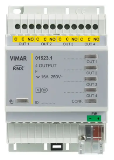 01523.1
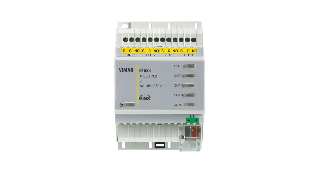
Multifunction actuator, 4 relay outputs, NO 16 A 250 V~.
BUILDING AUTOMATION
WELL-CONTACT PLUS
For details of the Well-contact Plus system, consult the installer manual, which can be downloaded from the
Download section Software Well-contact Plus on the website www.vimar.com.
output device
General characteristics and functions
Actuator with 4 NO relay outputs 16 A 250 V~, programmable with control function for lights, roller shutters with slat orientation, push buttons for local control, KNX standard, installation on DIN rails (60715 TH35), occupies 4 modules size 17.5 mm.
General characteristics
The device is designed to manage 4 generic outputs for typical applications in the service industry (access to offices, hospital or hotel rooms, swimming pools, saunas, sports facilities, restricted access areas, etc.).
It is also designed to work as a virtual pocket function for the presence control in the room.
Outputs 1-2 and 3-4 can be used to control roller shutters or Venetian blinds.
Functions
The functions available are the same for all channels.
For “Single outputs”, the following functions are available for the outputs:
- Disabled channel without function;
- Switching module the output is switched according to the other parameters;
- Stair light depending on the other parameters, the output is switched for a period of time (one-position stable relay).
Two outputs can be grouped together (OUT1/OUT2 and OUT3/ OUT4 to obtain the following functions: - Roller shutter
- Venetian blinds
Manual operation
Press the push button to enter manual mode to check the output connections. Press push buttons OUT1, OUT2, OUT3, OUT4 to control the related outputs. During manual operation, outputs OUT1/OUT2 and OUT3/OUT4 are interlocked to prevent damaging any motors connected, and messages received from the bus are not managed.
Behavior after powering on/off the Bus
Bus off: depending on the parameter settings.
Bus on: depending on the parameter settings.
Behavior after reset
As for Bus power-on.
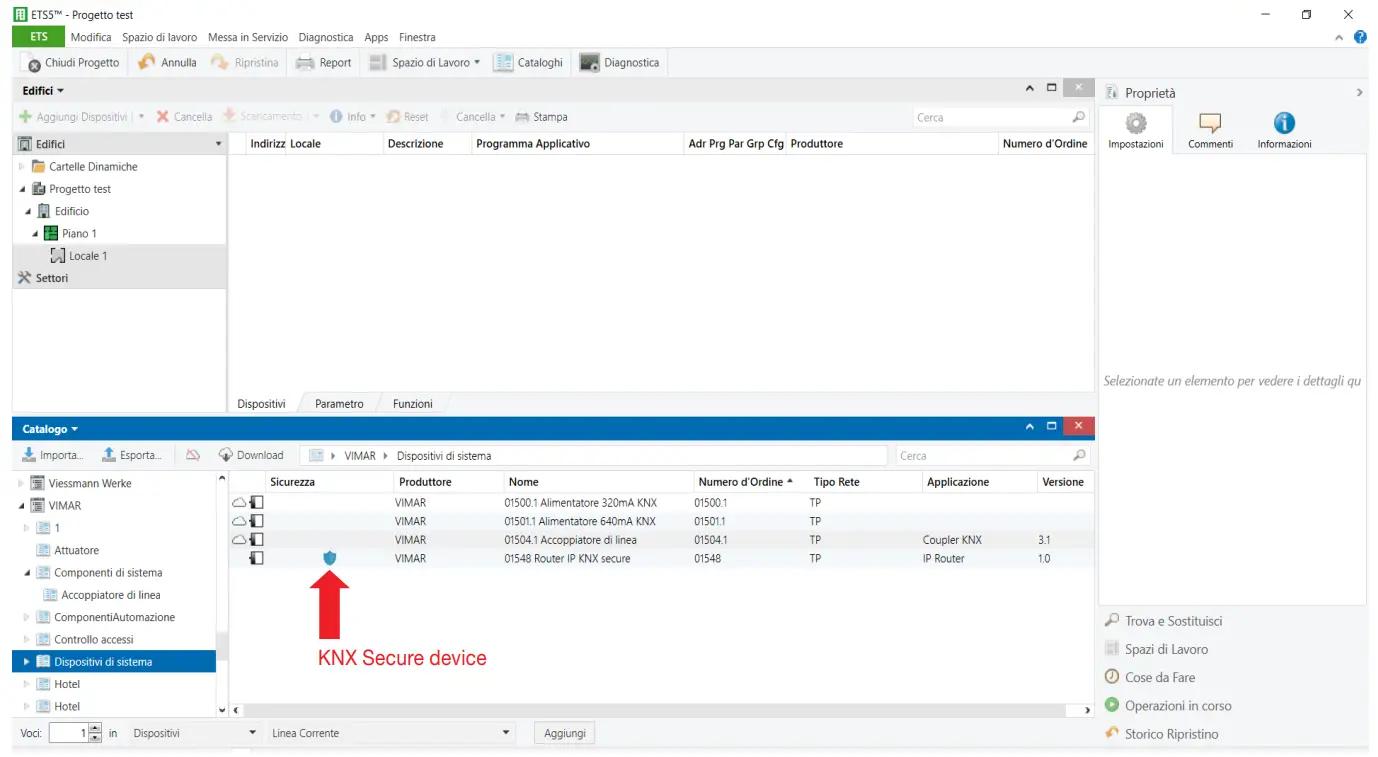
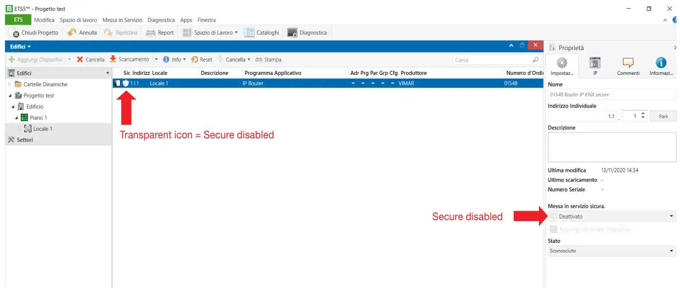
The KNX Secure protocol
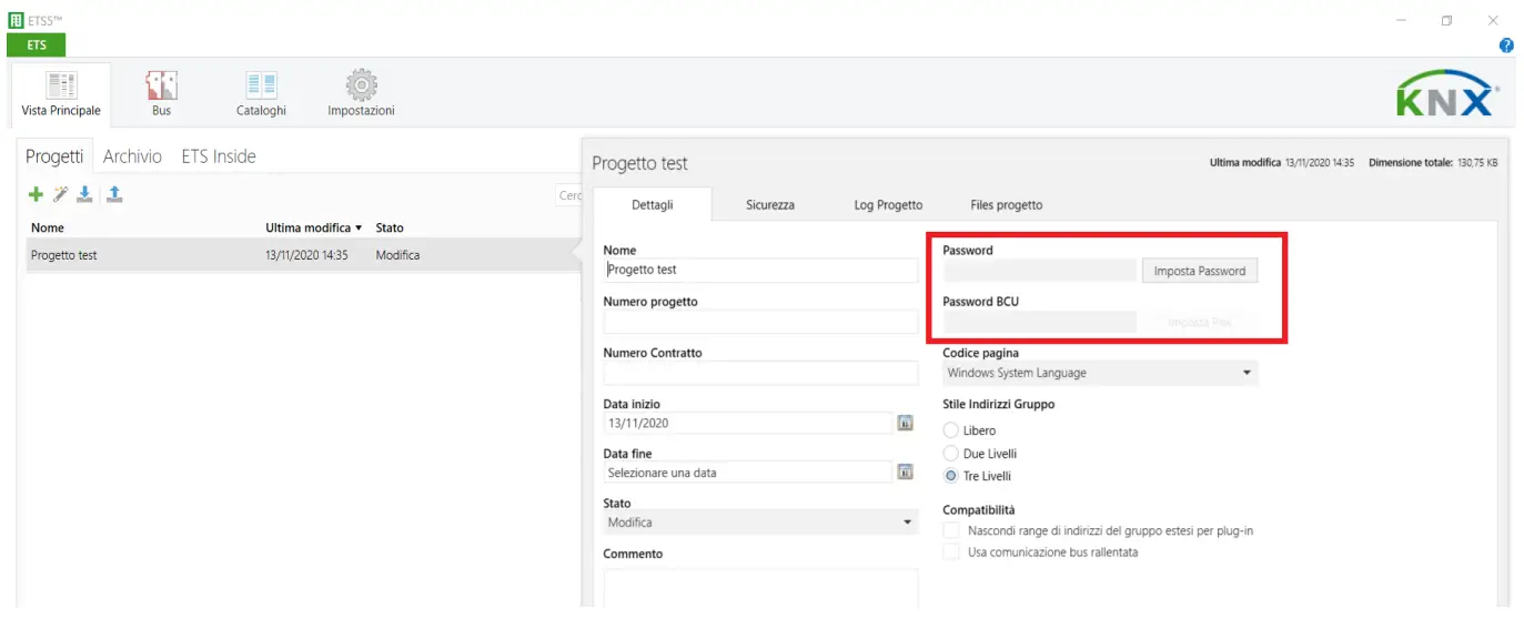
The device is used to activate the “KNX SECURE” data encryption protocol, entering the QR code or the digits in ETS and also creating a password associated to the project.
Note: If the QR code printed on the label is too small, take a photo of it with a smartphone and enlarge it.
The password is mandatory in the following cases:
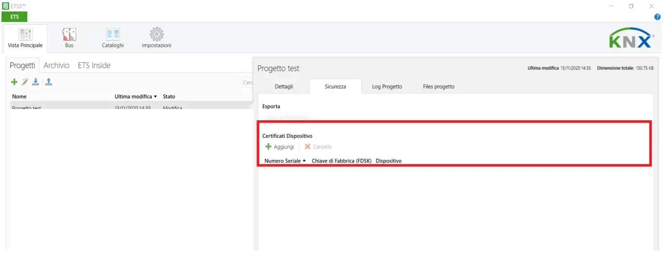
– when enabling the Secure part of the devices in the project – when entering the certificate of a Secure device in the project
If the Secure part of a device is disabled, it acts exactly like a device that does not support this protocol.
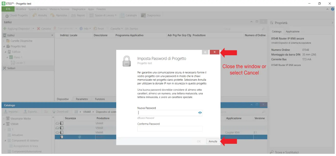
If you do not wish to enable the Secure part when importing the device into the project close the Secure request window as described in the following procedure.
- Add the Secure device to the ETS project.

- Ignore the set password request.

- The device is displayed with the Secure part disabled.

- No password is associated to the project.

- No certificate is associated to the project.

List of existing communication objects
The following objects are available for each channel, depending on the function and settings; they are identical for every channel or for pairs of channels used for roller shutters. If a channel is not on there are no communication objects.
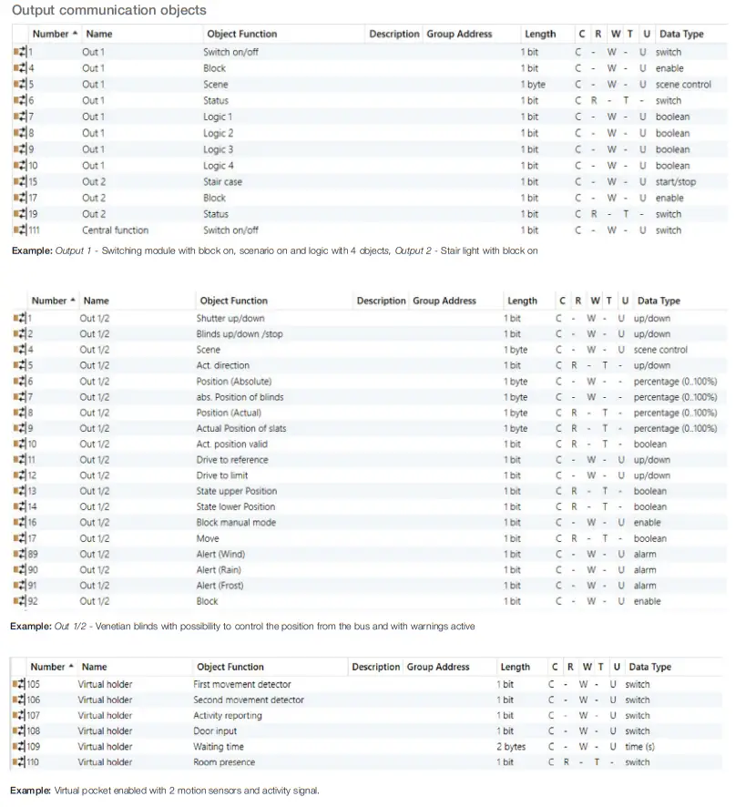
Communication objects per channel
| Number | Name in ETS | Function in ETS | Description | Length | Flag 1 | ||||
| C | R | W | T | U | |||||
| OUTPUTS With outputs OUT1, OUT2, OUT3 and OUT4 configured as single outputs | |||||||||
| 1 | Out 1 | On/ off | (If the output is enabled as “Switching module”) to switch the output On/ Off | 1 bit | X | X | X | ||
| 2 | Out 1 | Stair light | (If the output is enabled as “Stair Light”) to switch the output on, with timed switch-off. | 1 bit | X | X | X | ||
| 3 | Out 1 | Force | (If the output “Block” parameter is on, with “Force” function) to force the output On/Off from the Bus | 2 bit | X | X | |||
| 4 | Out 1 | Block | ((If the output “Block” parameter is on, with “Block” function) to block the output control from the Bus | 1 bit | X | X | X | ||
| 5 | Out 1 | Scenario | (If the output “Scenario” parameter is on), to activate and, if required, store (if the parameter is active) a scenario associated to the output | 1 byte | X | X | X | ||
| 6 | Out 1 | State | (If the output is enabled as “Switching module”) to know the output state | 1 bit | X | X | X | ||
| 7… 13 | Out 1 | Logic 1… 7 | (If the logic function for the output is on) A number of objects from 1 to 7 can be selected for OR, AND, XOR logics with the “On/off” object to determine the output state. | 1 bit | X | X | X | ||
| 14… 26 | Out 2 (see similar objects for Out 1) | As per Out 1 | |||||||
| 27… 39 | Out 3 (see similar objects for Out 1) | As per Out 1 | |||||||
| 40… 52 | Out 4 (see similar objects for Out1) | As per Out 1 | |||||||
| OUTPUTS With outputs OUT1/OUT2 and OUT3/OUT4 configured as roller shutter or Venetian blinds | |||||||||
| 1 | Out 1/2 | Roller shutter Up/Down | (If the output is enabled as “Roller shutter” or “Venetian blinds”) To move the Venetian blinds/roller shutter. | 1 bit | X | X | X | ||
| 2 | Out 1/2 | Slats up/down/stop | (If the output is enabled as “Venetian blinds”) To rotate/stop the slats. | 1 bit | X | X | X | ||
| 3 | Out 1/2 | Stop | (If the output is on as “Roller shutter”) To stop the roller shutter. | 1 bit | X | X | X | ||
| 4 | Out 1/2 | Scenario | (If the output is on as “Venetian blinds” or “Roller shutter” and “Scenario” is on) To call up the scenarios from the Bus. | 1 byte | X | X | X | ||
| 5 | Out 1/2 | Actual direction | (If the output is on as “Venetian blinds” or “Roller shutter” and “select objects for absolute position” is on) Object signalling the roller shut- ter direction of movement. Reading the state, the object responds with the last movement made or the current one if the roller shutter is moving (1 = up, 0 = down). | 1 bit |
X |
X |
X | ||
| 6 | Out 1/2 | Position (Absolute) | (If the output is on as “Venetian blinds” or “Roller shutter” and “select objects for absolute position” is on) To set the roller shutter position from a supervisor (0% = all up, 100% = all down. | 1 byte | X | X | |||
| 7 | Out 1/2 | Absolute slat position | (If the output is on as “Venetian blinds” and “select objects for absolute position” is on) To set the slat position from a supervisor (0% = open, 100% = closed). | 1 byte | X | X | |||
| 8 | Out 1/2 | Position (Actual) | (If the output is on as “Venetian blinds” or “Roller shutter” and “select objects for absolute position” is on) To know the actual position of the roller shutter (0% = all up, 100% = all down. | 1 byte | X | X | X | ||
| 9 | Out 1/2 | Current slat position | (If the output is on as “Venetian blinds” and “select objects for absolute position” is on). To know the actual slat position. | 1 byte | X | X | X | ||
| 10 | Out 1/2 | Valid actual position | (If the output is on as “Venetian blinds” or “Roller shutter” and “select ob- jects for absolute position” is on) To know the actual roller shutter position. | 1 bit | X | X | X | ||
| 11 | Out 1/2 | Door to reference | (If the output is on as “Venetian blinds” or “Roller shutter” and “select objects for absolute position” is on) Object used to move the roller shutter Up/Down: sends a bit= 1 to the Bus to raise or a bit=0 to lower (the device will ignore all other commands sent to the Bus until the output switches off within the set time) | 1 bit |
X |
X |
X | ||
| 12 | Out 1/2 | Door at limit | (If the output is enabled as “Venetian blinds” or “Roller shutter” and the “Driving Area – Limitation” is on) Object used to move the roller shutter Up/ Down: receives a bit =1 from the Bus to raise or a bit = 0 to lower. | 1 bit | X | X | X | ||
| 13 | Out 1/2 | Upper state – Position | (If the output is on as “Venetian blinds” or “Roller shutter” and “select ob- jects for absolute position” is on) The device sends a bit to 1 when the upper limit stop is reached. | 1 bit | X | X | X | ||
Continued
| Number | Name in ETS | Function in ETS | Description | Length | Flag 1 | ||||
| C | R | W | T | U | |||||
| 14 | Out 1/2 | Lower state – Position | (If the output is on as “Venetian blinds” or “Roller shutter” and “select ob-jects for absolute position” is on) The device sends a bit to 1 when the lower limit stop is reached. | 1 bit | X | X | X | ||
| 15 | Out 1/2 | Automatic lock | (If the output is enabled as “Venetian blinds” or “Roller shutter” and “Automatic roller shutter operation” is on) To enable/disable the automatic operation (rain, wind, etc.). | 1 bit | X | X | X | ||
| 16 | Out 1/2 | Lock mode manual | (If the output is enabled as “Venetian blinds” or “Roller shutter”) To enable/ disable the manual operation (controlled from a button via Bus). | 1 bit | X | X | X | ||
| 17 | Out 1/2 | Move | (If the output is on as “Venetian blinds” or “Roller shutter” and “select objects for absolute position” is on) An object that sends a bit = 1 when the movement starts, or a bit = 0 when the movement ends. It is also possible to read the current state. | 1 bit | X | X | X | ||
| 89 | Out 1/2 | Warning (Wind) | (If the output is enabled as “Venetian blinds” or “Roller shutter” and the “Warning Function” is on with “Warning Wind”) to move the roller shutter/ Venetian blinds to the position for this type of warning set in the specific parameters. | 1 bit | X | X | X | ||
| 90 | Out 1/2 | Warning (Rain) | (If the output is enabled as “Venetian blinds” or “Roller shutter” and the “Warning Function” is on with “Warning Rain”) to move the roller shutter/ Venetian blinds to the position for this type of warning set in the specific parameters. | 1 bit | X | X | X | ||
| 91 | Out 1/2 | Warning (Frost) | (If the output is enabled as “Venetian blinds” or “Roller shutter” and the “Warning Function” is on with “Warning Frost”) to move the roller shutter/ Venetian blinds to the position for this type of warning set in the specific parameters. | 1 bit | X | X | X | ||
| 92 | Out 1/2 | Block | (If the output is enabled as “Venetian blinds” or “Roller shutter” and the “Warning Function” is on with “Block”) to block the roller shutter at the limit stop with a bit to “1” (upper or lower, according to the parameters). | 1 bit | X | X | X | ||
| 97 | Automatic A | Automatic operation 1 – Position | (If the “Automatic operation” parameter of “Block-A” is on) To automatically control this roller shutter output object which can recall specific positions similar to scenarios. | 1 bit | X | X | |||
| 98 | Automatic A | Automatic operation 2 – Position | (If the “Automatic operation” parameter of “Block-A” is on) To automatically control this roller shutter output object which can recall specific positions similar to scenarios. | 1 bit | X | X | |||
| 99 | Automatic A | Automatic operation 3 – Position | (If the “Automatic operation” parameter of “Block-A” is on) To automatically control this roller shutter output object which can recall specific positions similar to scenarios. | 1 bit | X | X | |||
| 100 | Automatic A | Automatic operation 4 – Position | (If the “Automatic operation” parameter of “Block-A” is on) To automatically control this roller shutter output object which can recall specific positions similar to scenarios. | 1 bit | X | X | |||
| 101 | Automatic B | Automatic operation 1 – Position | (If the “Automatic operation” parameter of “Block-B” is on) To automatically control this roller shutter output object which can recall specific positions similar to scenarios. | 1 bit | X | X | |||
| 102 | Automatic B | Automatic operation 2 – Position | (If the “Automatic operation” parameter of “Block-B” is on) To automatically control this roller shutter output object which can recall specific positions similar to scenarios. | 1 bit | X | X | |||
| 103 | Automatic B | Automatic operation 3 – Position | (If the “Automatic operation” parameter of “Block-B” is on) To automatically control this roller shutter output object which can recall specific positions similar to scenarios. | 1 bit | X | X | |||
| 104 | Automatic B | Automatic operation 4 – Position | (If the “Automatic operation” parameter of “Block-B” is on) To automatically control this roller shutter output object which can recall specific positions similar to scenarios. | 1 bit | X | X | |||
| VIRTUAL POCKET | |||||||||
| 105 | Virtual pocket | First motion sensor | (If the “Virtual pocket” function is on) To receive an indication from a motion sensor. | 1 bit | X | X | X | ||
| 106 | Virtual pocket | Second motion sensor | (If the “Virtual pocket” function is on and the “Second motion sensor” is enabled) To receive an indication from a second motion sensor. | 1 bit | X | X | X | ||
| 107 | Virtual pocket | Activity signaling | (If the “Virtual pocket” function is on and “Activity signaling” is enabled) To receive an indication from a second motion sensor. | 1 bit | X | X | X | ||
| 108 | Virtual pocket | Door input | (If the “Virtual pocket” function is on) To receive an indication on the door opening and closing. | 1 bit | X | X | X | ||
| 109 | Virtual pocket | Wait time | (If the “Virtual pocket” function is on) To receive a value via bus for the Wait time. | 1 byte | X | X | X | ||
| 110 | Virtual pocket | Presence in room | (If the “Virtual pocket” function is on) To transit a bit=1 to signal that the room is occupied and a bit=0 to signal that the room is free. | 1 bit | X | X | X | ||
Communication objects per channel: once for all channels
| Number | Function | Use | DPT | Direction |
| 111 | Centralized function | Simultaneous on/off of more than one output configured as “Switching module” or “Stair light”. For “Stair light” the “Stair light time” is not considered and so the output must be switched off from the “Centralised function”. | DPT 1.001 | In, Write |
Standard communication object settings
Communication objects: default output/input settings
| Number | Name in ETS | Function in ETS | Length | Priority | Flag 1 | ||||
| C | R | W | T | U | |||||
| 1 | Out 1 | On/off | 1 bit | Low | X | X | X | ||
| 2 | Out 1 | Stair light | 1 bit | Low | X | X | X | ||
| 3 | Out 1 | Force | 2 bit | Low | X | X | X | ||
| 4 | Out 1 | Block | 1 bit | Low | X | X | X | ||
| 5 | Out 1 | Scenario | 1 byte | Low | X | X | X | ||
| 6 | Out 1 | State | 1 bit | Low | X | X | X | ||
| 7 | Out 1 | Logic 1 | 1 bit | Low | X | X | X | ||
| 8 | Out 1 | Logic 2 | 1 bit | Low | X | X | X | ||
| 9 | Out 1 | Logic 3 | 1 bit | Low | X | X | X | ||
| 10 | Out 1 | Logic 4 | 1 bit | Low | X | X | X | ||
| 11 | Out 1 | Logic 5 | 1 bit | Low | X | X | X | ||
| 12 | Out 1 | Logic 6 | 1 bit | Low | X | X | X | ||
| 13 | Out 1 | Logic 7 | 1 bit | Low | X | X | X | ||
| 14… 52 | Out 2, Out 3, Out 4 | As per Out 1 | |||||||
| 1 | Out 1/2 | Roller shutter Up/Down | 1 bit | Low | X | X | X | ||
| 2 | Out 1/2 | Slats up/down/stop | 1 bit | Low | X | X | X | ||
| 3 | Out 1/2 | Stop | 1 bit | Low | X | X | X | ||
| 4 | Out 1/2 | Scenario | 1 byte | Low | X | X | X | ||
| 5 | Out 1/2 | Actual direction | 1 bit | Low | X | X | X | ||
| 6 | Out 1/2 | Position (Absolute) | 1 byte | Low | X | X | |||
| 7 | Out 1/2 | Absolute slat position | 1 byte | Low | X | X | |||
| 8 | Out 1/2 | Position (Actual) | 1 byte | Low | X | X | X | ||
| 9 | Out 1/2 | Current slat position | 1 byte | Low | X | X | X | ||
| 10 | Out 1/2 | Valid actual position | 1 bit | Low | X | X | X | ||
| 11 | Out 1/2 | Door to reference | 1 bit | Low | X | X | X | ||
| 12 | Out 1/2 | Door at limit | 1 bit | Low | X | X | X | ||
| 13 | Out 1/2 | Upper state – Position | 1 bit | Low | X | X | X | ||
| 14 | Out 1/2 | Upper – Lower state | 1 bit | Low | X | X | X | ||
| 15 | Out 1/2 | Automatic lock | 1 bit | Low | X | X | X | ||
| 16 | Out 1/2 | Manual lock mode | 1 bit | Low | X | X | X | ||
| 17 | Out 1/2 | Move | 1 bit | Low | X | X | X | ||
| 89 | Out 1/2 | Warning (Wind) | 1 bit | Low | X | X | X | ||
| 90 | Out 1/2 | Warning (Rain) | 1 bit | Low | X | X | X | ||
| 91 | Out 1/2 | Warning (Frost) | 1 bit | Low | X | X | X | ||
| 92 | Out 1/2 | Block | 1 bit | Low | X | X | X | ||
| 27… 43 93… 96 | Out 3/4 | As per Out 1/2 | |||||||
| 97 | Automatic A | Automatic operation 1 – Position | 1 bit | Low | X | X | X | ||
| 98 | Automatic A | Automatic operation 2 – Position | 1 bit | Low | X | X | X | ||
| 99 | Automatic A | Automatic operation 3 – Position | 1 bit | Low | X | X | X | ||
| 100 | Automatic A | Automatic operation 4 – Position | 1 bit | Low | X | X | X | ||
| 101 | Automatic B | Automatic operation 1 – Position | 1 bit | Low | X | X | X | ||
| 102 | Automatic B | Automatic operation 2 – Position | 1 bit | Low | X | X | X | ||
Continued
| Number | Name in ETS | Function in ETS | Length | Priority | Flag 1 | ||||
| C | R | W | T | U | |||||
| 103 | Automatic B | Automatic operation 3 – Position | 1 bit | Low | X | X | X | ||
| 104 | Automatic B | Automatic operation 4 – Position | 1 bit | Low | X | X | X | ||
| 111 | Centralized function | On/off | 1 bit | Low | X | X | X | ||
| 105 | Virtual pocket | First motion sensor | 1 bit | Low | X | X | X | ||
| 106 | Virtual pocket | Second motion sensor | 1 bit | Low | X | X | X | ||
| 107 | Virtual pocket | Activity signaling | 1 bit | Low | X | X | X | ||
| 108 | Virtual pocket | Door input | 1 bit | Low | X | X | X | ||
| 109 | Virtual pocket | Wait time | 2 byte | Low | X | X | X | ||
| 110 | Virtual pocket | Presence in room | 1 bit | Low | X | X | X | ||
Reference ETS parameters
General
The following parameters are exclusive for all channels.
Output configuration
Define the output details.
| ETS text | Values available | Comment |
| [Default value] | ||
| Outputs: – Out 1/2 – Out 3/4 | 0 = Off | For “Single output” you can choose “Switching module” or “Stair light” corresponding- ing to a two-position stable or one-position stable relay. |
| 1 = Single output | ||
| 2 = Venetian blinds | ||
| 3 = Roller shutter | ||
| [0] | ||
| Interlock enabled | 0=off | Only one output (e.g. for the fan coil) can be on at a time |
| 1=on | ||
| [0] | ||
|
Enabled for outputs | 3 = A B |
If “interlock enabled”: out- puts for which it will be on. If “A B” for example, it will not be possible to activate Out 1 and 2 at the same time |
| 5 = A C | ||
| 9 = A D | ||
| 6 = B C | ||
| 10 = B D | ||
| 12 = C D | ||
| 7 = A B C | ||
| 11 = A B D | ||
| 13 = A C D | ||
| 14 = B C D | ||
| 15 = A B C D | ||
| [7] |
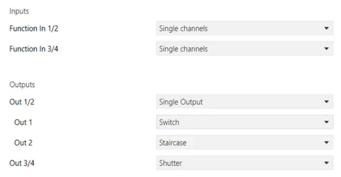
Channel configuration. (Example: Output 1 – Switching module, Output 2 – Stair light, Output 3/4 – Roller shutter)
Outputs
Output: switching module 1… 4
The following parameters are available for each channel and are identical for all of them.
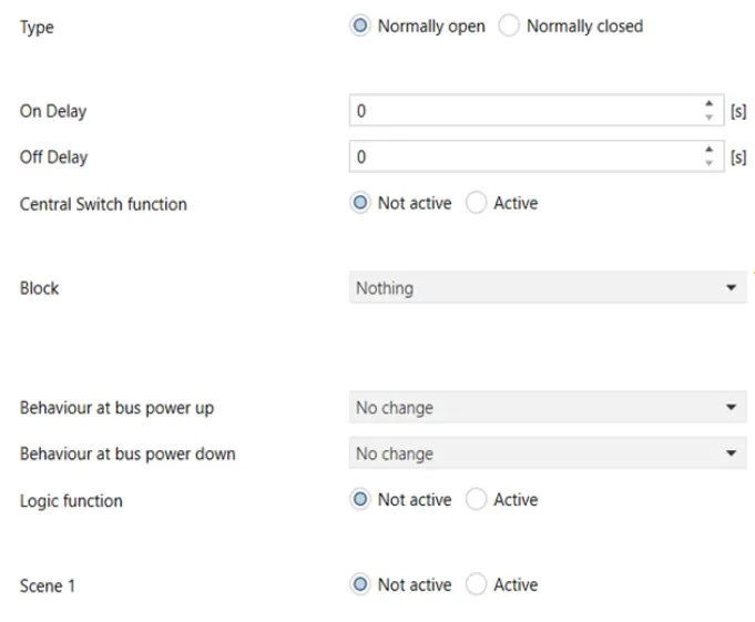
Parameter configuration
Management of outputs 1/2/3/4 set as switching module.
| ETS text | Values available | Comment |
| [Default value] | ||
| Type | 0 = normally closed | To define if the relay output is normally open or closed |
| 1 = normally open | ||
| [1] | ||
| Activation delay | 0… 30000 s | Activation delay in seconds |
| [0] | ||
| Deactivation delay | 0… 30000 s | Deactivation delay in seconds |
| [0] | ||
| Centralised control function | 0 = off | Centralized function (to control more than one output from the Bus at the same time) |
| 1 = on | ||
| [0] | ||
| Block/Force | 0 = no action | To block or force output from the Bus |
| 1 = Block | ||
| 2 = Force | ||
| State at block state start | 0 = Off | If block on |
| 1 = On | ||
| 2 = no change | ||
| [2] | ||
| State at block state end | 0 = Off |
If block on |
| 1 = On | ||
| 2 = no change | ||
| [2] | ||
| Behavior at Bus power on | 0 = Off | To define the relay output state at bus power on |
| 1 = On | ||
| 2 = no change | ||
| [2] |
| Continued | ||
| ETS text | Values available | Comment |
| [Default value] | ||
| Behavior at Bus power off | 0 = Off | To define the relay output state at bus power off |
| 1 = On | ||
| 2 = no change | ||
| [2] | ||
| Logic function | 0 = off | To enable logics on the outputs (AND, OR, XOR) for up to 7 objects |
| 1 = on | ||
| [0] | ||
| Scenario | 0 = off | Scenario activation If on, an additional page is displayed (Output, second- any element scenario) |
| 1 = on | ||
| [0] |
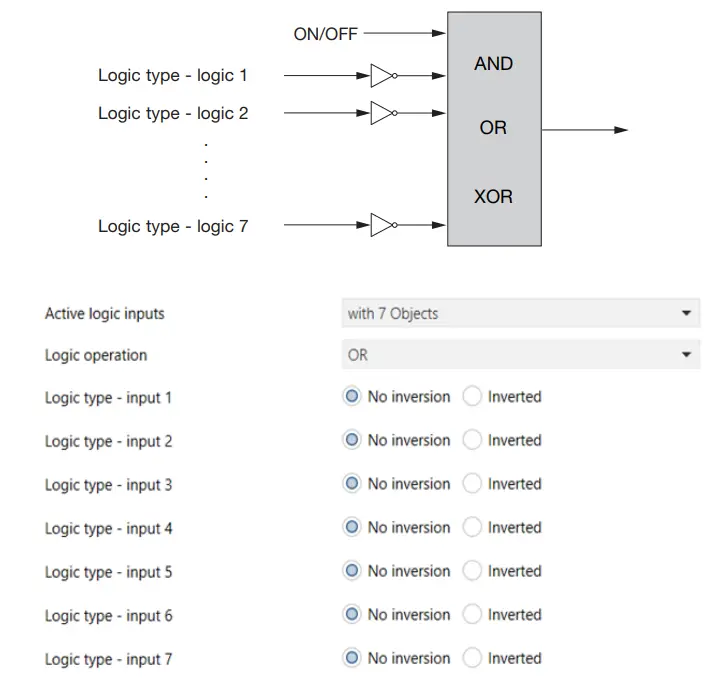
Logic function
The on/off objects can be used with logic objects (1 to 7) to create AND/OR/XOR logic functions to enable or disable the related output (OUT1, OUT2, OUT3, OUT4).
Parameter configuration
| ETS text | Values available | Comment |
| [Default value] | ||
| Logic inputs on | With 1 object | To enable the objects required for the logic |
| …. | ||
| With 7 objects | ||
| [With 1 object] | ||
| Logic operation | 0 = OR | To select the required logic operation |
| 1 = AND | ||
| 2 = XOR | ||
| [OR] | ||
| Logic type – input | Not inverted | To define if the selected in- put must be inverted or not |
| Inverted | ||
| [Not inverted] |
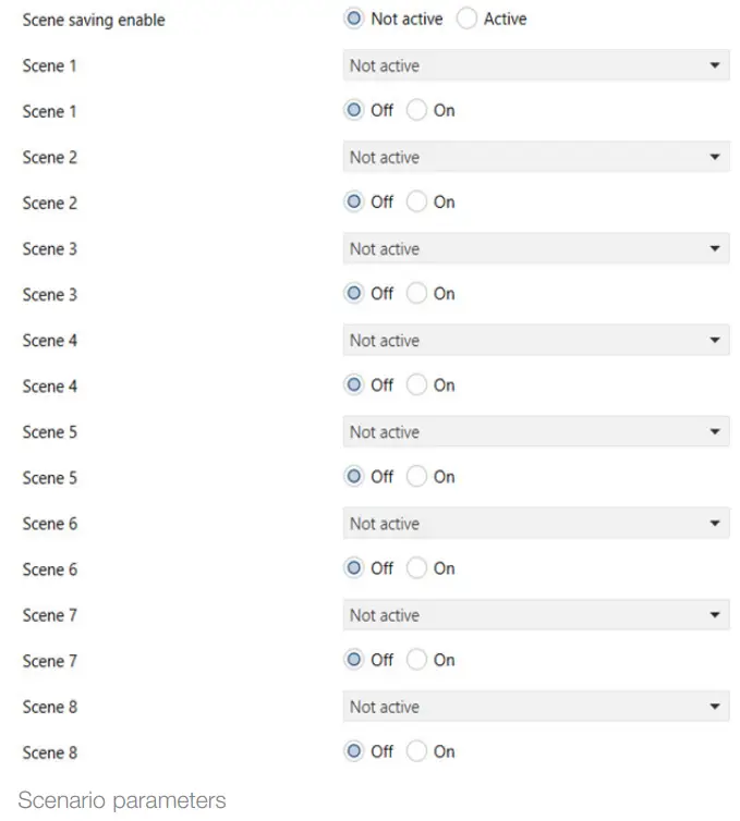
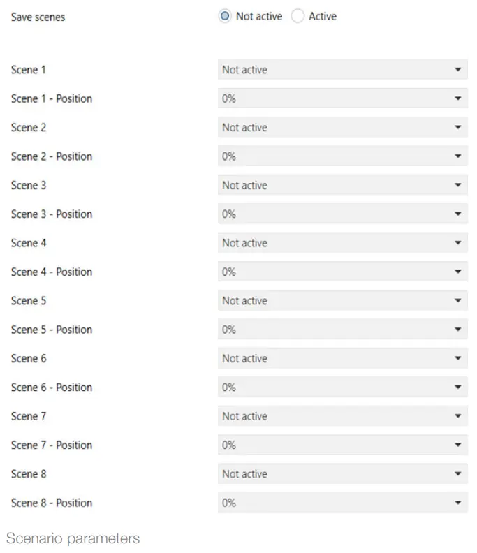
Output, secondary element scenario
For each output, 8 scenario storage possibilities are available.
For each scenario, the scenario index and the On or Off value for the output can be selected.
Scenario parameters (8 scenarios per output)
| ETS text | Values available | Comment |
| [Default value] | ||
| Store scenarios | 0 = Off | The “Store scenarios” func- tion is used to store the state linked to a scenario with a message from the Bus (scene learn). |
| 1 = On | ||
| [0] | ||
| Scenario 1 | Off | Used to select the scenario index. |
| 1… 64 | ||
| [Off] | ||
| Scenario 1 | 0=Off | To define the relay output state when scenario called up. |
| 1=On | ||
| [0] | ||
| Scenario 2 | Off | Used to select the scenario index. |
| 1… 64 | ||
| [Off] | ||
| Scenario 2 | 0=Off | To define the relay output state when the scenario is called up. |
| 1=On | ||
| [0] | ||
| Scenario 3 | Off | Used to select the scenario index. |
| 1… 64 | ||
| [Off] | ||
| Scenario 3 | 0=Off | To define the relay output state when the scenario is called up. |
| 1=On | ||
| [0] | ||
| Scenario 4 | Off | Used to select the scenario index. |
| 1… 64 | ||
| [Off] | ||
| Scenario 4 | 0=Off | To define the relay output state when the scenario is called up. |
| 1=On | ||
| [0] | ||
| Scenario 5 | Off | Used to select the scenario index. |
| 1… 64 | ||
| [Off] | ||
| Scenario 5 | 0=Off | To define the relay output state when the scenario is called up. |
| 1=On | ||
| [0] | ||
| Scenario 6 | Off | Used to select the scenario index. |
| 1… 64 | ||
| [Off] | ||
| Scenario 6 | 0=Off | To define the relay output state when the scenario is called up. |
| 1=On | ||
| [0] | ||
| Scenario 7 | Off | Used to select the scenario index. |
| 1… 64 | ||
| [Off] | ||
| Scenario 7 | 0=Off | To define the relay output state when the scenario is called up. |
| 1=On | ||
| [0] | ||
| Scenario 8 | Off | Used to select the scenario index. |
| 1… 64 | ||
| [Off] | ||
| Scenario 8 | 0=Off | To define the relay output state when the scenario called up. |
| 1=On | ||
| [0] | ||
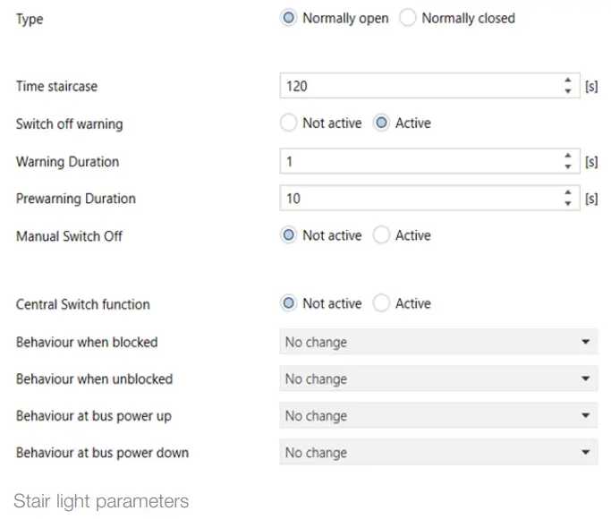
Output, timed stair light
The following parameters are available for each channel and are identical for all of them. If a channel is configured as stairs the The following parameters are visible:
Stair light parameters (one-position stable output management)
| ETS text | Values available | Comment |
| [Default value] | ||
| Type | 0=normally closed | To define if the relay output is normally open or closed |
| 1=normally open | ||
| [0] | ||
| Stair Light time [s] | 0… 65535 | Output activation time |
| [120] | ||
| Warning off | 0=off | To be able to switch the warning function on |
| 1=on | ||
| [0] | ||
| Duration of warning [s] | 0… 65535 | If “Off warning” is on: having set a “warning time” and a “prewarning time”, when the relay is switched off after the “stair light time” set, this remains Off for a time equal to the “warning time” and then comes on again for a time equal to the “prewarn- ing time” |
| [120] | ||
| Duration of pre-warning [s] | 0… 65535 | Warning time (if “Off warning” is on). Three times will be added. Having set a “warning time” and a “prewarning time”, when the relay is switched off after the “stair light time” set, this remains Off for a time equal to the “warning time” and then comes on again for a time equal to the “prewarn- ing time” |
| [120] | ||
| Manual off | 0=off | If manual off is active, on receiving an OFF message on the “Stair light” object, if on in one-position stable the output switches off |
| 1=on | ||
| [0] | ||
| Centralized switching module function | 0=off | To control more than one output from the Bus at the same time |
| 1=on | ||
| [0] | ||
| State at block state start | 0=Off | If block on |
| 1=On | ||
| 2=no change | ||
| [2] | ||
| State at the end of the block state | 0=Off | If block on |
| 1=On | ||
| 2=no change | ||
| [2] | ||
| Behavior when powering up the Bus | 0=Off | To define the relay output state at bus power on |
| 1=On | ||
| 2=no change | ||
| [2] | ||
| Behavior at Bus power off | 0=Off | To define the relay output state at bus power off |
| 1=On | ||
| 2=no change | ||
| [2] |
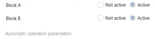
Automatic parameter activation
These settings activate objects. Each block has 4 objects, used to automatic controls on 4 objects calling up positions (similar to scenarios).
Parameters in automatic operation
| ETS text | Values available | Comment |
| [Default value] | ||
| Block A | 0=off | For block A objects 1-4 are activated |
| 1=On | ||
| [0] | ||
| Block B | 0=off | For block B objects 1-4 are activated |
| 1=On | ||
| [0] |
Parameters
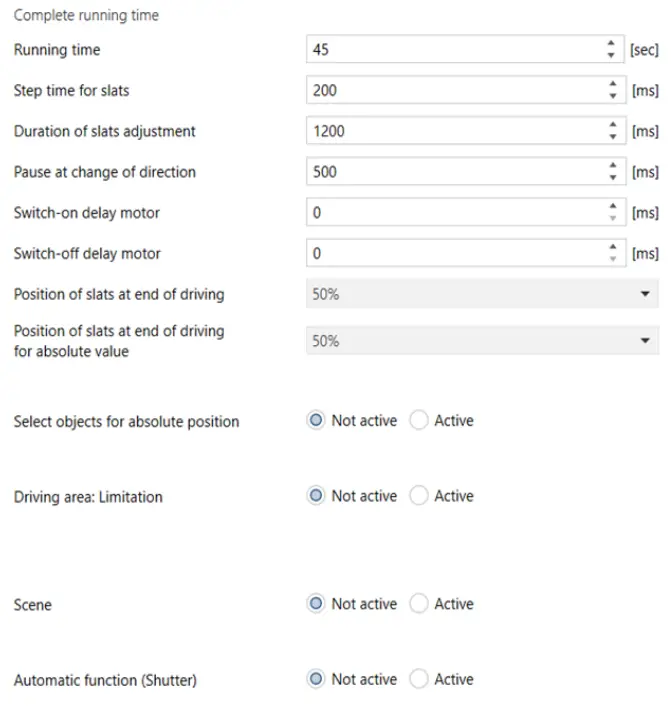
Venetian blinds parameters: characteristics relating to the control of Venetian blinds with slats
| ETS text | Values available | Comment |
| [Default value] | ||
| Execution time (sec) | 1-10000 | Movement time if not stopped |
| [45] | ||
| Step time for slats (ms) | 100-1000 | Sets the short press time for the button to interpret as slat control |
| [200] | ||
| Slat control time (ms) | 10-10000 | Sets the slat control time for each press |
| [1200] | ||
| Pause at change of direction (ms) | 1-1000 | Sets the delay time between the command and the change of direction |
| [500] | ||
| Motor start delay (ms) | 0-255 | Sets the delay time between the command and the start of movement (useful for motor starting) |
| [0] | ||
| Motor power-off delay (ms) | 0-255 | Sets the delay time between the command and the end of the movement (limit stop) |
| [0] | ||
| Slat position at end of driving | 0%-100% | Sets the slat position at the end from the reference travel 0-100% having set the limit stop (100% closed) |
| [50] | ||
| Slat position at end of driving by absolute value. | 0%-100% | Sets the slat position at the end of the movement due to the “Position (absolute)” object |
| [50] | ||
| Object selection for absolute position | 0=off | For feedback on the position on a supervisor, if on, 0%=all up and 100%=all down |
| 1=on | ||
| [0] | ||
| Reaction after driving to reference | 0=no reaction | Only if Position absolute |
| 1=Door to the previous position | ||
| [0] | ||
| Driving area: Limitation | 0= off | Only if the limitation on: sets the upper/lower thresholds of the Venetian blind travel to stop it before the limit stop |
| 1=on | ||
| [0] | ||
| Lower limit | 0%-100% | Only if limitation on (driving area) (100% = closed) |
| [0%] |
 Venetian blinds parameters
Continued
| ETS text | Values available | Comment |
| [Default value] | ||
| Upper limit | 0%-100% | Only if limitation on (driving area) (100% = closed) |
| [100%] | ||
| Scenario | 0= off | Enables the Venetian blind to be included in scenarios |
| 1=on | ||
| [0] | ||
| Automatic Operation | 0= off | Defines the possibility of having the Venetian blind possibilities with 4 objects devoted to their automatic control from the Bus (Rain, Wind, Frost, Block) |
| 1=on | ||
| [0] | ||
|
Warning Function | 0= off | Used to view the section with “Warning-Out” parameters, to enable the ETS obtaining to be switched on/ off (e.g. a weather station) and obtain the automatic movement of the Venetian blinds in the event of rain, wind, frost, block-out |
| 1=on | ||
| [0] |
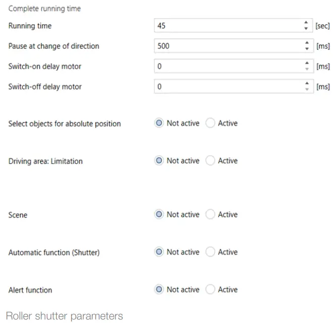
Roller shutter parameters: characteristics relating to the control of roller shutters (without slats)
| ETS text | Values available | Comment |
| [Default value] | ||
| Execution time (sec) | 1-10000 | Movement time if not stopped |
| [45] | ||
| Pause at the change of direction (ms) | 100÷1000 | Sets the delay time between the command and the change of direction |
| [500] | ||
| Motor start delay | 0÷255 | Sets the delay time between the command and the start of movement (useful for motor starting) |
| [0] | ||
| Motor power-off delay | 0÷255 | Sets the delay time between the command and the end of movement (limit stop) |
| [0] | ||
| Select objects for absolute position | 0 = Off | Selects the possibility or not to use communication objects to view the actual position of the roller shutter (0%=all up, 100%=all down) for feedback of the position on a supervisor |
| 1 = Door to previous position | ||
| [0] | ||
| Reaction after driv- ing to reference | 0 = No reaction | If “Select objects for absolute position” on |
| 1 = Door to the previous position | ||
| [0] | ||
| Driving area: limi- tation | 0 = Off | Only if the limitation on: sets the upper/lower thresholds. of the Venetian blind travel to make it stop before the limit stop |
| 1 = On | ||
| [0] | ||
| Lower limit | 0%… 100% | If “Driving area” on (100% = closed) |
| [0%] | ||
| Upper limit | 0%… 100% | If “Driving area” on (100% = closed) |
| [100%] | ||
| Scenario | 0 = Off | Enables the roller shutter to be included in scenarios |
| 1 = On | ||
| [0] |
Continued
| ETS text | Values available | Comment |
| [Default value] | ||
| Automatic oper- ation | 0 = Off | Defines the possibility of having the required roller shutter position with 4 objects devoted to their automatic control from the Bus (rain, wind, frost, block) |
| 1 = On | ||
| [0] | ||
| Warning Function | 0 = Off | Used to view the section with “Warning-Out” parameters, to enable the ETS obtaining to be switched on/ off (e.g. a weather station) and obtain the automatic movement of the roller shutters in the event of rain, wind, frost, block-out |
| 1 = On | ||
| [0] |
Scenarios
For each channel, 8 scenarios can be stored and called up. For each scenario, it is possible to select the scenario index, the position of the roller shutter and slats (only for Venetian blinds).
Scenario parameters: scenario management
| ETS text | Values available | Comment |
| [Default value] | ||
| Store scenarios | 0=off | The “Store scenarios” function is used to store the state linked to a scenario with a message from the Bus (scene learn). |
| 1=on | ||
| [0] | ||
| Scenario 1 | 1-64 | Used to select the scenario index. |
| Off | ||
| [Off] | ||
| Scenario 1 Position | 0%-100% | Used to select the roller shutter position when the scenario is called up |
| [0] | ||
| Scenario 1 – Slats position | 0%-100% | Used to select the position of the slats when the scenario is called up (Venetian blinds only) |
| [0] | ||
| … | ||
| Scenario 8 |
The Store scenarios function is used to store the state linked to a scenario with a message from the Bus (scene learn).
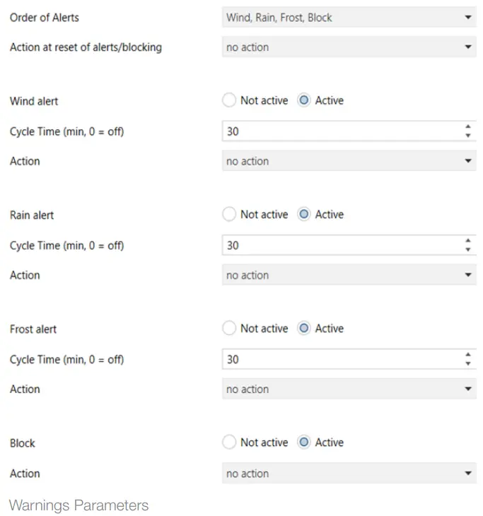
Warnings Out 1/2 and 3/4
Warnings Parameters: if the “Warning Function” parameter is enabled on the output, to define the operations to be performed automatically in the event of the objects “Rain, Wind, Frost, Block” being activated by the Bus (by interaction with weather stations)
| ETS text | Values available | Comment |
| [Default value] | ||
| Warning order | 0 = Wind, Rain, Frost, Block | To give a priority to the warnings |
| 1 = Wind, Rain, Block, Frost | ||
| 2 = Wind, Block, Rain, Frost | ||
| 3 = Block, Wind, Rain, Frost | ||
| [0] | ||
| Action after warn- ings/block reset | 0 = No action | What the output does (Vene- tian blinds/roller shutter) when the warning or block ends |
| 4 = Door to previous position | ||
| 1 = Door to higher level | ||
| 2 = Door to lower level | ||
| [0] | ||
| “Wind” warning | 0 = Off | |
| 1 = On | ||
| [0] | ||
| Cycle time (min, 0 = Off) | 0-120 | From the moment the alarm is triggered, a time can be set after which the alarm condition is reset (if no other messages are received) |
| [30] | ||
| Action | 0 = No action | Defines what happens in the event of a “Wind” alarm |
| 1 = Door to higher level | ||
| 2 = Door to lower level | ||
| [0] | ||
| “Rain” warning | 0 = Off | |
| 1 = On | ||
| [0] | ||
| Cycle time (min, 0 = Off) | 0-120 | From the moment the alarm is triggered, a time can be set after which the alarm condition is reset (if no other messages are received) |
| [30] | ||
| Action | 0 = No action | Defines what happens in the event of a “Rain” alarm |
| 1 = Door to higher level | ||
| 2 = Door to lower level | ||
| [0] | ||
| “Frost” warning | 0 = Off | |
| 1 = On | ||
| [0] |
Continued
| ETS text | Values available | Comment |
| [Default value] | ||
| Cycle time (min, 0 = Off) | 0-120 | From the moment the alarm is triggered, a time can be set after which the alarm condition is reset (if no other messages are received) |
| [30] | ||
| Action | 0 = No action | Defines what happens in the event of a “Frost” alarm |
| 1 = Door to higher level | ||
| 2 = Door to lower level | ||
| [0] | ||
| Block | 0 = Off | |
| 1 = On | ||
| [0] | ||
| Action | 0 = No action | |
| 1 = Door to higher level | ||
| 2 = Door to lower level | ||
| [0] |
Automatic operation
In this point, the object block and required position are assigned, if the “Automatic operation” parameter is enabled on the output.
Automatic parameters
| ETS text | Values available | Comment |
| [Default value] | ||
| Automatic objects | Block A | The automatic operations are divided into 2 blocks A and B that can be associat- ed to outputs 1/2 and 3/4. |
| Block B | ||
| [Block A] | ||
| Automatic opera- tion 1 (-4) – Position | 0%-100% | For each of the 4 automatic operations, it is possible to define the roller shutter position (100% = Closed) |
| [0%] | ||
| (-4) – Blind position | 0%-100% | For each of the 4 automatic operations, it is possible to define the slat position (100% = Closed) |
| [0%] |
Note.
Automatic 1 = position 1 – position 2 – position 3 – position 4.
Automatic 2 = position 1 – position 2 – position 3 – position 4.
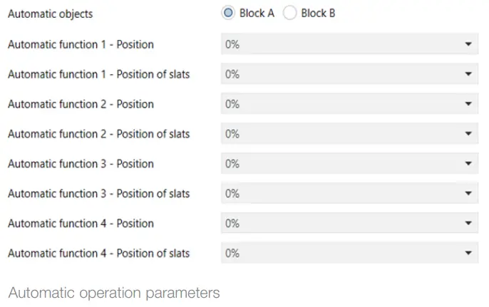
Automatic operation parameters
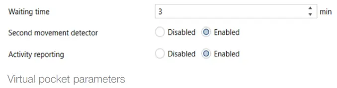
Virtual pocket
The virtual pocket function can be enabled by selecting “Enabled” in the “Output Configuration” page. This function is used to check if a room is occupied and signal it in the 1 bit object “Presence in the room”. To implement the function, at least a motion sensor and a room access door opening and closing signal must be used. The use of another motion sensor or the configuration of an object signaling activity in the room are optional. The following parameters are available for this function
| ETS text | Values available | Comment |
| [Default value] | ||
| Wait time | 0÷65535 min | To select the presence in room detection wait time from the bus |
| [5] | ||
| Second motion sensor | Disabled | To enable a second motion sensor that can signal the presence in the room |
| Enabled | ||
| [Disabled] | ||
| Activity signalling | Disabled | If this parameter is enabled, any command received on the “Activity signalling” object signals the presence in the room |
| Enabled | ||
| [Disabled] |
The following graphics illustrate some cases of using the “virtual pocket” function. In all cases, the door opening and closing is signaled (received on the “Door input” object), as is the movement on a PIR (received on the “First motion sensor” object) and the room occupied is sent (on the “Presence in room” object).
General note: The motion sensor disabling time must be less than the timeout (“Wait time” parameter or “Wait time” object) for leaving the room. In this way, at the end of the timeout, the “Presence in the room” signal is disabled and the room can be placed in the “not occupied” state. 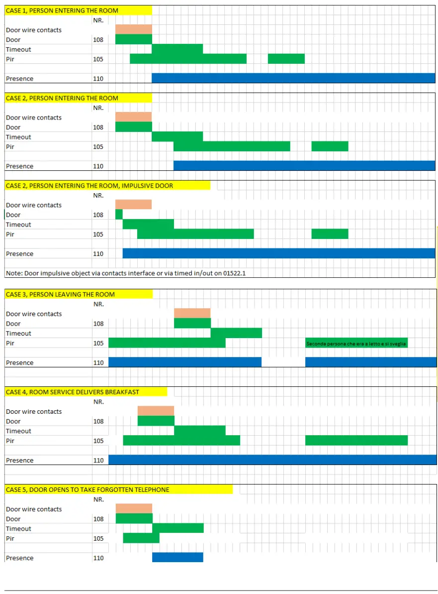
![]() Viale Vicenza 14
Viale Vicenza 14
![]() 36063 Marostica VI – Italy
36063 Marostica VI – Italy
www.vimar.com
01523.1IEN 01 2011


