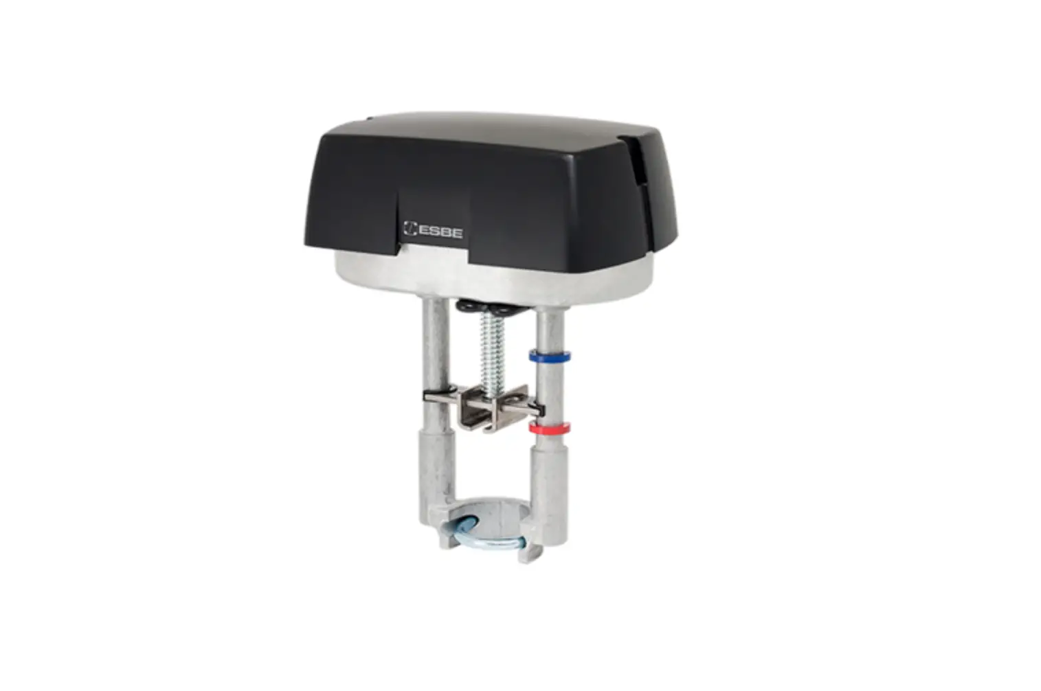
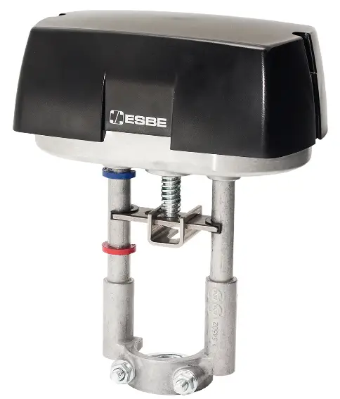
ESBE ALFxx4 24V Actuator
INSTALLATION
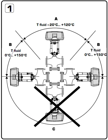
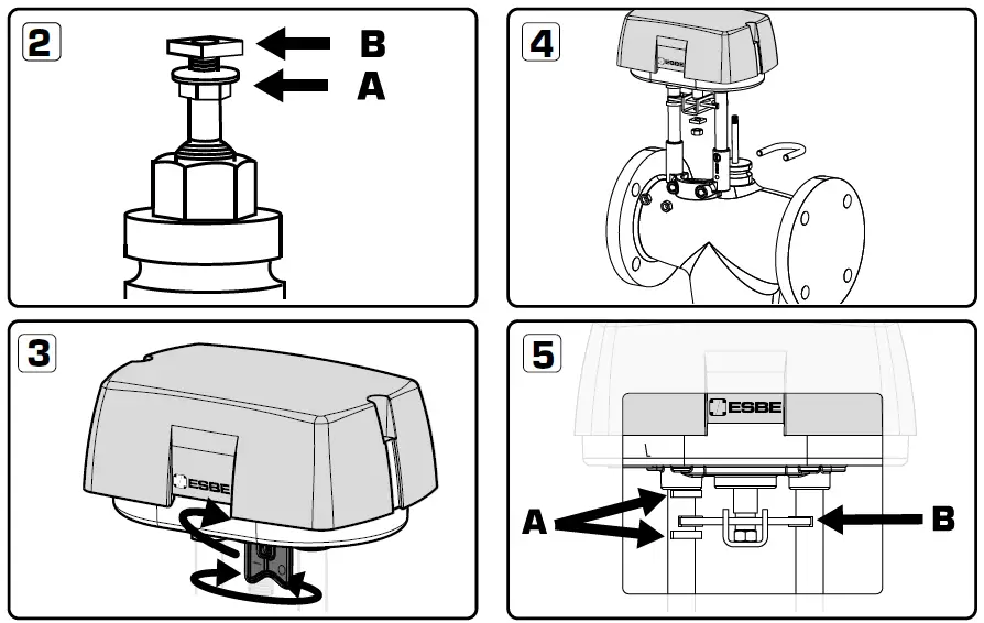
- Mounting positions:
- Allowed mounting position with fluid temperature between –20ºC to +120ºC.
- Allowed mounting position with fluid temperature between 0ºC to +150ºC
- Not allowed mounting position.
- Mount flange nut (A) and then the square nut (B) on top of spindle.
- Bring the actuator into desired position by activating and turning the manual knob (more information on page 6), or reposition the valve itself.
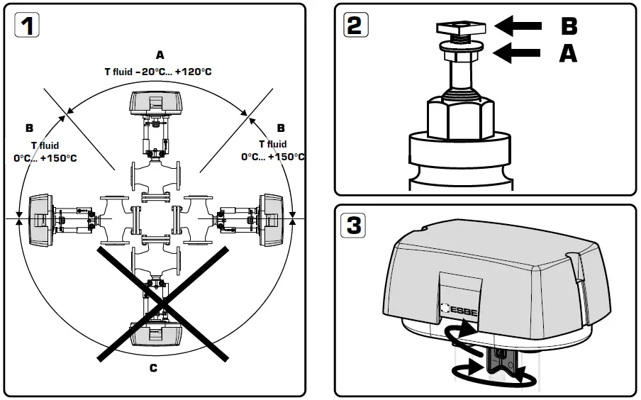
- Put the actuator on top of the valve. Fasten it to the neck of the valve by means of the U-bolt. Firmly tighten all nuts!
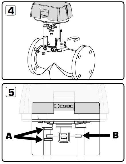
- Stroke indicator B: Anti rotation guide


MANUAL OVERRIDE
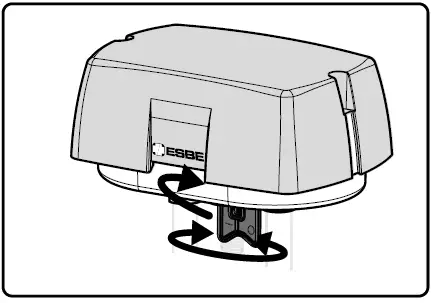
There is a manual operation handle on the actuator. When handle is lowered manual operation is active, the power supply to the motor power stage circuitry is cut and the motor stop. The actuator can be operated manually and the valve positioned accordingly. The manual operation handle latches in position until it is raised again, then board and motor will be powered again. At the end of this operation the actuator moves to initial position (on the basis of DIP 1 setting) then it follows the control signal. When the manual override handle is engaged, the green and the red LED are on.
The actuator is supplied with the manual operation handle lowered/active.
CONNECTOR DESCRIPTIONS
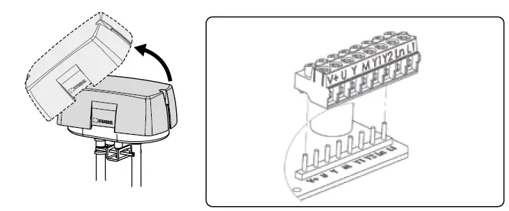
To avoid damages to electronic components caused by the PCB bending, do not press too much while fixing the terminal block.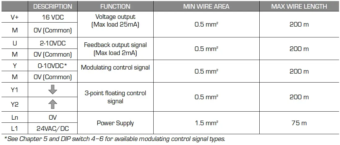
- See Chapter 5 and DIP switch 4−6 for available modulating control signal types.
ELECTRICAL CONNECTION
ALFxx4 contain a half-wave rectifier power supply. It shall not be powered with transformers that are used to power other devices using non isolated full-wave rectifier power supply. Use cable gland PG13,5 model (not supplied)
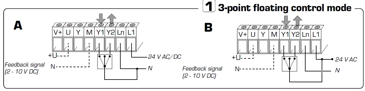
point floating control mode
In floating control mode is only DIP switch 2 applicable. In floating control mode is DIP switch 7 used only to force manual calibration. During floating control mode the automatic calibration is not active.
point floating control mode (Sink connection)
Connect wires, pict. A. Connect (Ln+Y1) to extend (open)![]() or (Ln+Y2) to retract (close)
or (Ln+Y2) to retract (close)![]() in floating control mode (Sink connection). Connect feedback signal if needed, pict. A. Start a calibration
in floating control mode (Sink connection). Connect feedback signal if needed, pict. A. Start a calibration
point floating control mode (Source connection)
Connect power wires according to to picture B. Connect (L1+Y1) to extend (open)![]() or (L1+Y2) to retract (close)
or (L1+Y2) to retract (close)![]() in floating control mode (Source connection). Connect feedback signal if needed, pict. B. Start a calibration
in floating control mode (Source connection). Connect feedback signal if needed, pict. B. Start a calibration
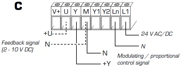
Modulating/proportional control mode
Connect power and control signal according to to picture C. Connect feedback signal if needed, pict. C. Set the DIP switches according to the information in chapter 5. Start a calibration.
Modulating/proportional control mode
DIP SWITCHES
It is not necessary to remove power supply to change DIP switch settings, but the 24V power supply must be consider. Before the cover on the actuator is removed and DIP settings are changed, the power to the actuator must be disconnected or manual operation handle active. After DIP settings are changed power up the actuator or inactivate manual operation handle to activate the new settings.
| DIP SWITCH | OFF | ON |
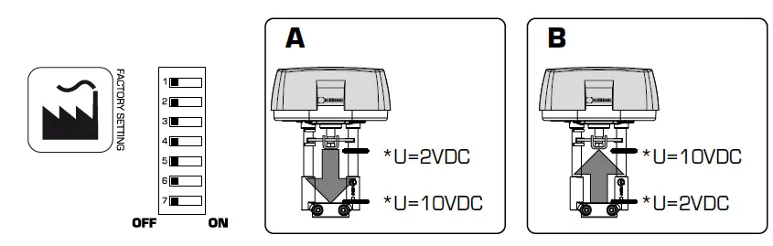
| 1 | Normal direction, picture A | Reverse direction, picture B |
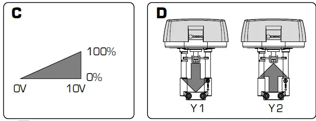
| 2 | Modulating / proportional control mode, picture C | 3-point floating control mode, see picture D |
| 3 | – | Sequence control mode |
| 4 | Modulating control signal 0-10 VDC | Modulating control signal 2-10 VDC |
| 5 | Sequence control signal 0-5 VDC with DIP switch 4 in OFF mode Sequence control signal 2-6 VDC with DIP switch 4 in ON mode | Sequence control signal 5-10 VDC with DIP switch 4 in OFF mode Sequence control signal 6-10 VDC with DIP switch 4 in ON mode |
| 6 | Voltage input signal (VDC) | Current input signal (4-20mA) Note: DIP switch 4 must be in ON mode |
| 7 | Automatic Calibration: the actuator updates the stroke range if an unexpected mechanical stop is detected for at least 10 seconds | Manual Calibration: the actutor calibration is started moving the switch from OFF to ON; if the switch is left in ON the actuator will never update the calibrated stroke value even when an unexpected endpoint is detected |
- U= feedback signal

DIAGNOSTIC / ALARM FUNCTION
| N° | LED | ERROR | WHEN | ACTUATOR BEHAVIOUR | TYPICAL TROUBLE SHOOTING CONDITION | RESET P ROCEDURE | |
| Automatic Calibration SW7 OFF | Manual Calibration SW7 ON | ||||||
|
1 |
RED ON |
Calibrated stroke valve less than 5 mm |
Calibration / first installation | The actuator pushes/ pulls 5 times (unexpected stall) trying to remove the possible obstacle. After 5 tries alarm is signalled (RED Led ON) and the actuator moves to initial position. Doesn’t respond to control signal. Stroke value is not updated beacuse out of range | The actuator pushes/pulls 2 times against endpoint during calibration. Alarm is signalled (RED led On) and the actuator moves to the initial position. Doesn’t respond to the control signal. |
Valve with a stroke length lower than 5 mm |
Remove power and power up again |
|
2 |
RED ON |
Stroke longer than 30/60 mm |
Calibration / first installation | The actuator exits the 30/60 mm stroke range and moves toward the new stroke limit signalling an anomaly (RED led on). The actuator doesn’t calibrate the stroke | The actuator pushes/pulls 2 times against endpoint during calibration. Alarm is signalled (RED led On) and the actuator moves to the initial position and then it doesn’t reposnd to the control signal. | Valve with a stroke length longer than 30/60 mm |
Remove power and power up again |
|
3 | RED quick * blinking + GREEN ON | Unexpected stall within the calibrated stroke range |
Normal operation | The actuator tries 5 times against the new stall condition. After 10 sec. the actuator updates the new stroke lenght. During these 10 sec. RED led is ON | The actuator tries 5 times against the new stall condition. After 10 sec. the actuator doesn’t update the new stroke lenght |
Valve stuck | Inverted control signal |
|
4 |
RED quick * blinking + GREEN ON |
Stroke longer than expected |
Normal operation | The actuator moves toward the new stall condition with a lower speed; after 10 sec. the actuator updates the new stroke value; During these 10 sec. RED led is ON |
The actuator moves toward the new stall condition with a lower speed. After 10 sec. the actuator doesn’t update the new stroke value |
Stem connection loose or valve damaged |
Inverted control signal |
|
5 | RED slow** blinking |
Low Power Voltage |
Normal operation | The actuator is still working but performance cannot be guaranteed | The actuator is still working but performance cannot be guaranteed | 1. Wrong transformer size | Correct Voltage Power |
| 2. Unstable power | |||||||
|
6 |
RED slow** blinking |
High Power Voltage |
Normal operation |
The actuator is still working but performance cannot be guaranteed |
The actuator is still working but performance cannot be guaranteed | 1. Wrong transformer size |
Correct Voltage Power |
| 2. Unstable power | |||||||
- Quick = 2 flash / second
- Slow = 1 flash / second
- LED´s are placed on circuit board and are only visible when actuator cover is removed
ACTUATOR STATUS
| N° | LED | ACTUATOR STATUS |
| 1 | Green On | The actuator arrived at the extreme point of the stroke read |
| 2 | Green Blinking | The actuator arrived at the intermediate point of the stroke read |
| 3 | Red Green Blinking | The actuator is reading the stroke or it is going to initial position |
| 4 | Red Green On | Manual operation active, the actuator ignores the control signal. ATTENTION! The PCB is electrically supplied |
- www.esbe.eu

- Mtrl.nr. 98141092 Ritn.nr. 6305 vers B
- Rev. 2022‒06‒01


 Instruction Manual")


