![]()
E01C-ML01SP4 Wireless Module
User Manual
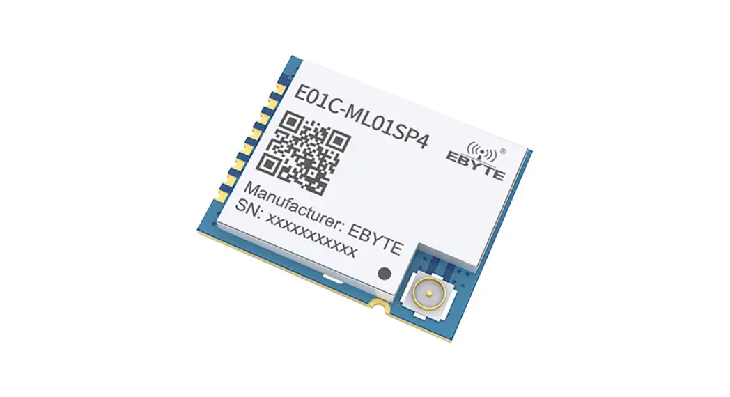
E01C-ML01SP4
SI24R1+ 2.4GHz 100mW SPI SMD Wireless Module
Chengdu Ebyte Electronic Technology Co., Ltd.
Disclaimer
EBYTE reserves all rights to this document and the information contained herein. Products, names, logos, and designs described herein may in whole or in part be subject to intellectual property rights. Reproduction, use, modification or disclosure to third parties of this document or any part thereof without the express permission of EBYTE is strictly prohibited.
The information contained herein is provided “as is” and EBYTE assumes no liability for the use of the information. No warranty, either express or implied, is given, including but not limited, with respect to the accuracy, correctness, reliability, and fitness for a particular purpose of the information. This document may be revised by EBYTE at any time. For the most recent documents, visit www.ebyte.com.
Overview
1.1 Introduction
E01C-ML01SP4 is a small size 2.4ghz SMD wireless module, a maximum transmitting power of 100mW, which is independently developed based on domestic SI24R1.
The built-in power amplifier (PA) and low noise amplifier (LNA) on the original basis, the maximum transmission power reaches 100mW, while the receiving sensitivity is further improved, and the overall communication stability is less than the power amplifier and low noise amplifier The products have been greatly improved.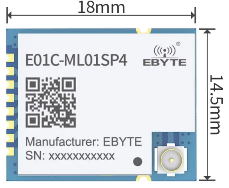
This product uses industrial-grade high-precision 16MHz crystal. Since E01C-ML01SP4 is a radio frequency transceiver module, it needs to use an MCU driver or use a dedicated SPI debugging tool.
1.2 Features
- Small size 14.5*18mm;
- The maximum transmit power is 100mW, software multi-level adjustable;
- Communication distance can reach 2KM under ideal conditions;
- Global license-freeISM2.4GHzband;
- Air data rate: 2Mbps, 1Mbps, and 250kbps; 125communication channel to meet the needs of multi-point communication, packet, frequency hopping, and other applications;
- Connect to MCU through SPI interface, the speed is 0 10Mbps;
- A power supply of 2.03.6V, more than 3.3V can guarantee the best performance;
- Professional RF shielding cover, anti-interference, anti-static;
- IPEX interface, convenient for connecting coaxial cable or external antenna (shared with IPEX interface);
1.3 Application
Smart home and industrial sensors; Security system, positioning system; Wireless remote control, drone; Wireless game remote control; Health care products; Wireless voice, wireless headphones; Automotive industry applications.
Technical Parameters
2.1 Limit Parameter
| Main parameter | Performance | Remarks | |
| Min | Max | ||
| Voltage supply(V) | 0 | 3.6 | Voltage over 3.6V will cause permanent damage to the module |
| Blocking power(dBm) | – | 10 | Chances of burn are slim when modules are used in short distance |
| Working temperature(℃) | -40 | 85 | Industrial |
2.2 Working parameters
| Main parameter | Performance | Remarks | |||
| Min. | Typ. | Max. | |||
| Operating voltage(V) | 2.0 | 3.3 | 3.6 | ≥3.3 V ensures output power | |
| Communication level(V) | 3.3 | For 5V TTL, it may be at risk of burning down | |||
| Working temperature(℃) | -40 | – | 85 | Industrial design | |
| Operating frequency(GHz) | 2.4 | – | 2.525 | Support ISM band | |
| Power consumption | TX current(mA) | 113 | Instant power consumption | ||
| RX current(mA) | 24 | ||||
| Sleep current (μA) | 2 | Software shut off | |||
| Max Tx Power(dBm) | 19.7 | 20 | 20.2 | ||
| Receiving sensitivity(dBm) | -96.5 | -96 | -97.5 | The Air data rate is 250kbps | |
| Air data rate(bps) | 250k | – | 2M | User programming control | |
Main parameter | Value | Remarks |
| Distance | 2000m | In open and clear air, at a height of 2.5m, the air data rate:250kbps |
| FIFO | 32Byte | Max packet length per time |
| Crystal Frequency | 16MHz | |
| Modulation | GFSK | |
| Package | SMD | |
| Connector | 1.27mm | |
| Communication interface | SPI | 0~10Mbps |
| Size | 14.5*18mm | Without SMA |
| Antenna | IPEX | 50-ohm impedance match |
Size and pin definition
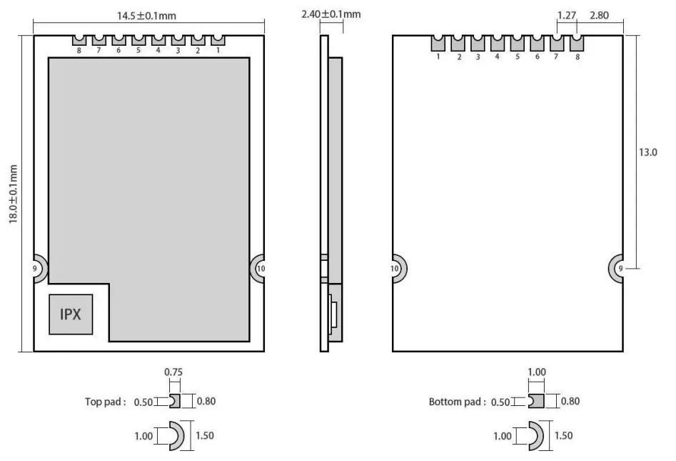
Pin No. | Pin item | Pin direction | Application |
| 1 | VCC | Power supply between 2.0 and 3.6V | |
| 2 | CE | Input | Module control pin |
| 3 | CSN | Input | Chip select pin for starting new SPI communication |
| 4 | SCK | Input | SPI clock pin |
| 5 | MOSI | Input | SPI data input pin |
| 6 | MISO | Output | SPI data output pin |
| 7 | IRAQ | Output | Interrupt request, valid in low level |
| 8 | GND | Ground, connected to power reference ground | |
| 9 | GND | Ground, connected to power reference ground | |
| 10 | GND | Ground, connected to power reference ground |
Basic operation
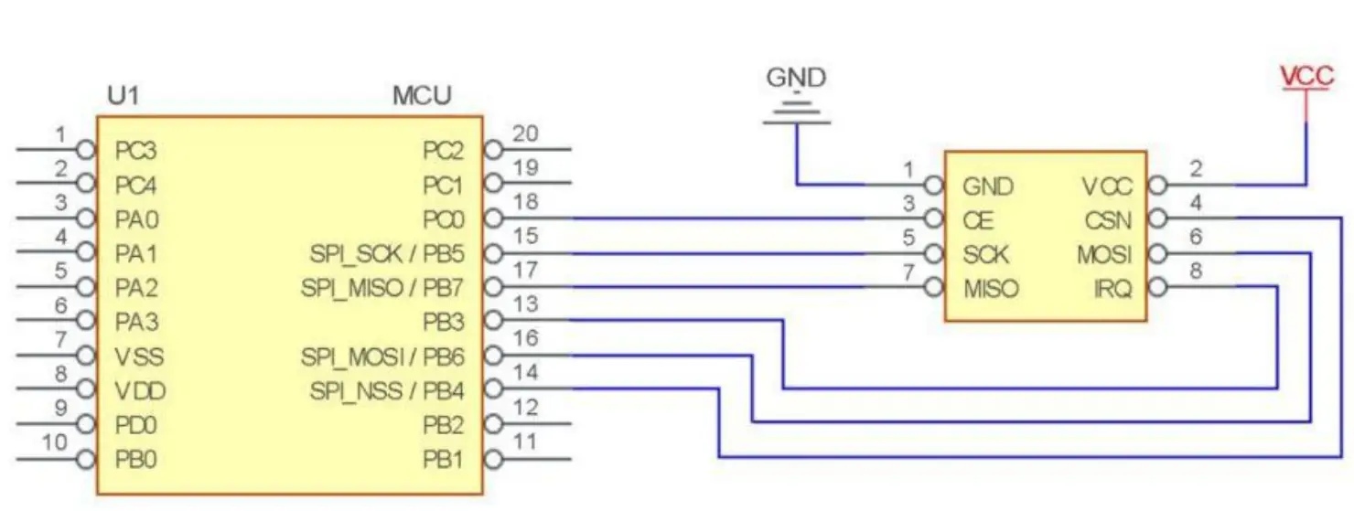
4.1 Hardware design
- It is recommended to use a DC stabilized power supply. The power supply ripple factor is as small as possible, and the module needs to be reliably grounded;
- Please pay attention to the correct connection of the positive and negative poles of the power supply. The reverse connection may cause permanent damage to the module
- Please check the power supply to ensure it is within the recommended voltage otherwise when it exceeds the maximum value the module will be permanently damaged
- Please check the stability of the power supply, the voltage cannot fluctuate frequently
- When designing the power supply circuit for the module, it is often recommended to reserve more than 30% of the margin, so the whole machine is beneficial for long-term stable operation;
- The module should be as far away as possible from the power supply, transformers, high-frequency wiring and other parts with large electromagnetic interference;
- Bottom LayerHigh-frequency digital routing, high-frequency analog routing, and power routing must be avoided under the module. If it is necessary to pass through the module, assume that the module is soldered to the Top Layer, and the copper is spread on the Top Layer of the module contact part(well-grounded), it must be close to the digital part of the module and routed in the Bottom Layer;
- Assuming the module is soldered or placed over the Top Layer, it is wrong to randomly route over the Bottom Layer or other layers, which will affect the module’s spurs and receiving sensitivity to varying degrees;
- It is assumed that there are devices with large electromagnetic interference around the module that will greatly affect the performance. It is recommended to keep them away from the module according to the strength of the interference. If necessary, appropriate isolation and shielding can be doneAssume that there are traces with large electromagnetic interference (high-frequency digital, high-frequency analog, power traces) around the module that will greatly affect the performance of the module. It is recommended to stay away from the module according to the strength of the interference. If necessary, appropriate isolation and shielding can be done;
- Try to stay away from some physical layers such as TTL protocol at 2.4GHz, for example, USB3.0;
- The antenna installation structure has a great impact on the performance of the module. Be sure to ensure that the antenna is exposed, preferably vertically. When the module is installed inside the case, a high-quality antenna extension cable can be used to extend the antenna to the outside of the case;
- Do not install the antenna inside the metal case,it will greatly reduce the transmission distance.
4.2 Software programming
This module is SI24R1+PA+LNA, and its driving mode is exactly the same as SI24R1. Users can operate in full accordance with the SI24R1 chip manual (see the SI24R1 manual for details);
Power step:
SI24R1Register setting table
Address(Hex) | Mnemonic | Bit | Reset Value | Description |
| 06 | RF_SETUP | Rf configuration | ||
| RF_PWR | 2:0 | 110 | TX transmitting power 111:7dBm 110:4dBm 101:3dBm 100:1dBm 011:0dBm 010:-4dBm 001:-6dBm 000:-12dBm |
- 010Front -4dBmoutput 17dBm
- 011Front -6dBmoutput 14dBm;
- 000Front -12dBmoutput 8dBm;
- IRQ is an interrupt pin. It is used to wake up the microcontroller and achieve fast response; users can leave it unconnected and use SPI to query the interrupt status (not recommended, not conducive to overall power consumption, low efficiency);
- CE can be connected to high level for a long time, but the module must be set to POWER DOWN powerdown mode when writing to the register. It is recommended that CE be controlled by MCU pin.
- The CE pin is connected to the LNA enable pin. When CE=1, LNA is turned on, and when CE=0, LNA is turned off. This operation is completely consistent with the transceiver mode of nRF24L01; in other words, the user does not need to care about LNA operation at all;
- If the user needs to answer automatically, the CE pin must remain high during transmission. The correct operation is: CE=1 to trigger the transmission. After knowing that the transmission is completed, CE=0, instead of CE=0 after 10us. The reason is: After SI24R1 is sent, it will immediately switch to receiving mode. At this time, if CE= 0, the LNA has been turned off, which is not conducive to receiving sensitivity.
Basic application
FAQ
6.1 Communication range is too short
- The communication distance will be affected when obstacle exists;
- Data loss rate will be affected by temperature, humidity, and co-channel interference;
- The ground will absorb and reflect wireless radio wave, so the performance will be poor when testing near ground.;
- Seawater has a great ability in absorbing wireless radio waves, so performance will be poor when testing near the sea;
- The signal will be affected when the antenna is near a metal object or put in a metal case;
- The Power register was set incorrectly, the air data rate is set as too high (the higher the air data rate, the shorter the distance);
- The power supply low voltage under room temperature is lower than 2.5V, the lower the voltage, the lower the transmitting power; Due to antenna quality or poor matching between antenna and module.
6.2 Module is easy to damage
- Please check the power supply to ensure that it is between the recommended power supply voltage. If the maximum value is exceeded, the module will be permanently damaged;
- Please check the stability of the power source, the voltage cannot fluctuate too much;
- Please make sure anti-static measures are taken when installing and using, high-frequency devices that have electrostatic susceptibility;
- Please ensure the humidity is within a limited range, some parts are sensitive to humidity;
- Please avoid using modules under too high or too low temperatures.
6.3 BER(Bit Error Rate) is high
- There are co-channel signal interference nearby, please be away from interference sources or modify frequency and channel to avoid interference;
- The clock waveform on the SPI is not standard. Check whether there is interference on the SPI line. The SPI bus line should not be too long;
- The poor power supply may cause messy code. Make sure that the power supply is reliable;
- The extension line and feeder quality are poor or too long, so the bit error rate is high.
Welding guidance
7.1 Reflow Soldering Temperature
Profile Feature | Sn-Pb Assembly | Pb-Free Assembly |
| Solder Paste | Sn63/Pb37 | Sn96.5/Ag3/Cu0.5 |
| Preheat Temperature min (Tsmin) | 100℃ | 150℃ |
| Preheat temperature max (Tsmax) | 150℃ | 200℃ |
| Preheat Time (Tsmin to Tsmax)(ts) | 60-120 sec | 60-120 sec |
| Average ramp-up rate(Tsmax to Tp) | 3℃/second max | 3℃/second max |
| Liquidous Temperature (TL) | 183℃ | 217℃ |
| Time(tL)Maintained Above(TL) | 60-90 sec | 30-90 sec |
| Peak temperature(Tp) | 220-235℃ | 230-250℃ |
| Aveage ramp-down rate(Tp to Tsmax) | 6℃/second max | 6℃/second max |
| Time 25℃ to peak temperature | 6 minutes max | 8 minutes max |
7.2 Reflow Soldering Curve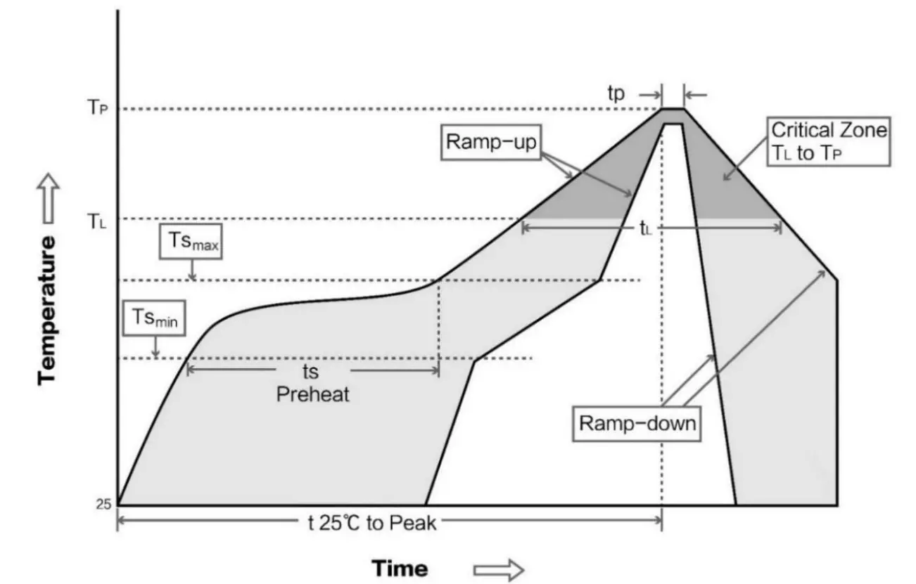
E01 series
| Model | IC | Frequency | Tx power | Distance | Package | Antenna |
| Hz | dBm | m | ||||
| E01-ML01S | nRF24L01+ | 2.4G | 0 | 100 | SMD | PCB |
| E01-ML01D | nRF24L01+ | 2.4G | 0 | 100 | DIP | PCB |
| E01-ML01IPX | nRF24L01+ | 2.4G | 0 | 200 | SMD | IPEX |
| E01-2G4M13S | nRF24L01+ | 2.4G | 13 | 1200 | SMD | PCB |
| E01-ML01SP2 | nRF24L01+ | 2.4G | 20 | 1800 | SMD | PCB/IPE X |
| E01-ML01SP4 | nRF24L01+ | 2.4G | 20 | 2000 | SMD | IPEX |
| E01-ML01DP4 | nRF24L01+ | 2.4G | 20 | 1800 | DIP | PCB |
| E01-ML01DP5 | nRF24L01+ | 2.4G | 20 | 2500 | DIP | SMA-K |
| E01-2G4M27D | nRF24L01+ | 2.4G | 27 | 5000 | DIP | SMA-K |
| All wireless modules of the E01 series can communicate with each other | ||||||
Antenna recommendation
9.1 Recommendation
The antenna is an important role in the communication process. A good antenna can largely improve the communication system. Therefore, we recommend some antennas for wireless modules with excellent performance and reasonable prices.
| Model No. | Type | Frequency | Gain dBi | Size | Cable | Interface | Function feature |
| Hz | dBi | mm | cm | ||||
| TX2400-NP-5010 | Flexible antenna | 2.4G | 2.0 | 10×50 | – | IPEX | FPC soft antenna |
| TX2400-JZ-3 | Rubber antenna | 2.4G | 2.0 | 30 | – | SMA-J | Short straight & omnidirectional |
| TX2400-JZ-5 | Rubber antenna | 2.4G | 2.0 | 50 | – | SMA-J | Short straight & omnidirectional |
| TX2400-JW-5 | Rubber antenna | 2.4G | 2.0 | 50 | – | SMA-J | Flexible & omnidirectional |
| TX2400-JK-11 | Rubber antenna | 2.4G | 2.5 | 110 | – | SMA-J | Bendable glue stick & omnidirectional |
| TX2400-JK-20 | Rubber antenna | 2.4G | 3.0 | 200 | – | SMA-J | Bendable glue stick & omnidirectional |
| TX2400-XPL-150 | Sucker antenna | 2.4G | 3.5 | 150 | 150 | SMA-J | Small & cost-effective |
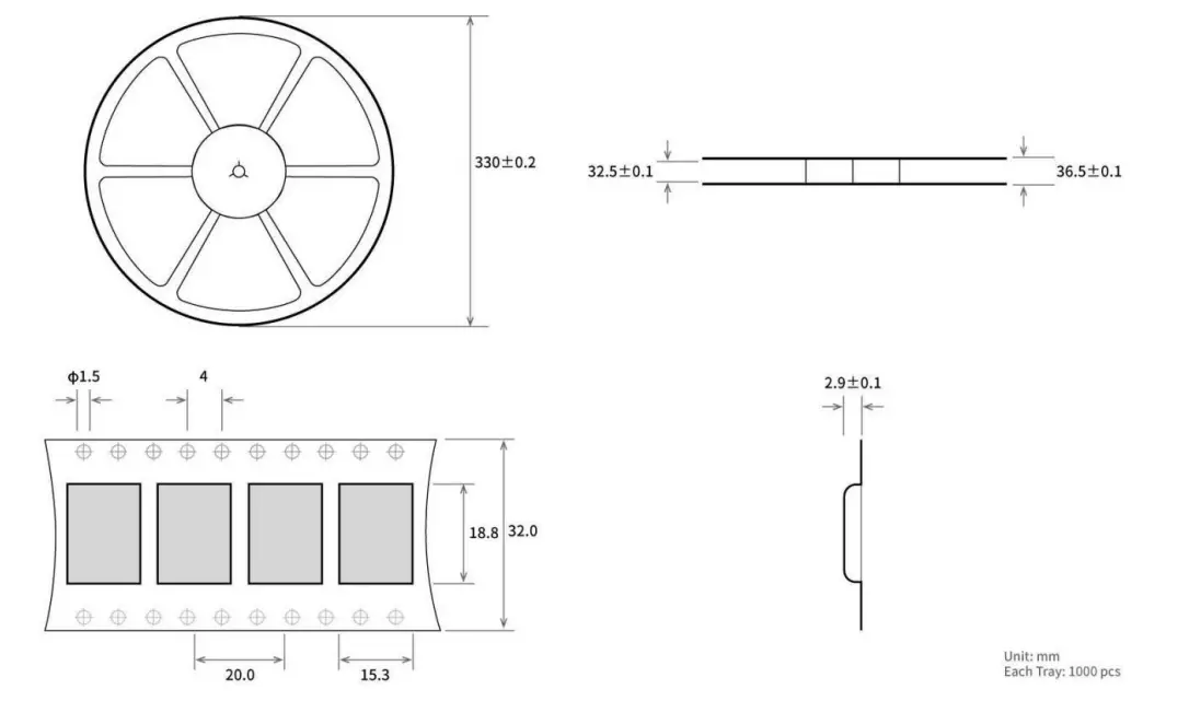
Batch packaging
Revision history
Version | Date | Description | Issued by |
| 1.0 | 2020-12-21 | Initial version | Linson |
About us
Technical support: [email protected]
Documents and RF Setting download link: www.ebyte.com
Thank you for using Ebyte products! Please contact us with any questions or suggestions: [email protected]
-Phone: +86 028-61399028
Web: www.ebyte.com
Address: B5 Mould Park, 199# Xiqu Ave, High-tech District, Sichuan, China
Copyright ©20122021
Chengdu Ebyte Electronic Technology Co., Ltd.![]()


