![]()
![]()
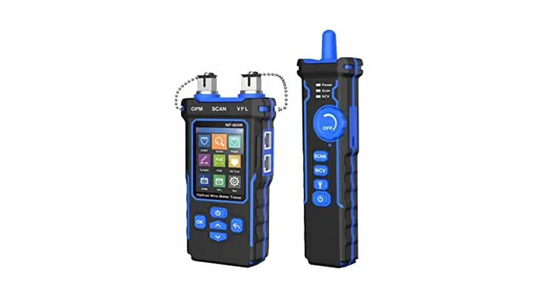
NF-8508 Optical Wire Meter Tracer
User Manual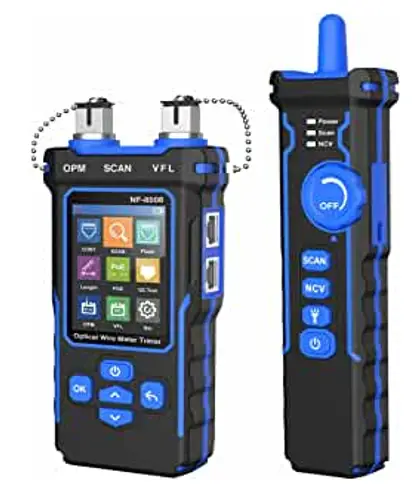
![]() Your excellent helpex in cable test!
Your excellent helpex in cable test!
User Manual
VER:V1
NF-8508
NF-8508 Optical Wire Meter Tracer
![]() Read the precautions before your operation
Read the precautions before your operation
The transmitter and receiver of this device are powered by lithium polymer batteries.
Please do not place the device in a location that is dusty, humid, or hot (above 40°C).
Please do not disassemble the device. Repair and maintenance should be done by a professional staff.
When not using the device for a longtime, please remove the battery to prevent the battery liquid from leaking out.
Please do not perform related operations on the communication line during thunderstorms to prevent lightning strikes and personal safety.
Product button and interface description
NF-8508 is an Optical wire meter tracer for home and public facility network cable repair.
Its main functions includes : Optical power meter & VFL function; Tracing cable location; Test cable continuity; Measuring cable length; PoE test; Port plash function; Crimping test for crystal head and so on. And It has two modes for options to trace cable like antijaming & normal mode.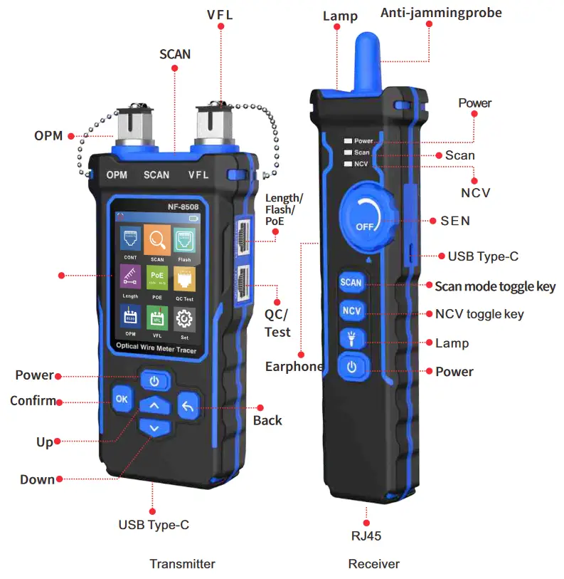 Auto power off icon
![]() When this icon is displayed it means that the auto power off function is on and when this icon is not displayed it means that the auto power off function is off.
When this icon is displayed it means that the auto power off function is on and when this icon is not displayed it means that the auto power off function is off.
Power display icon![]() Displays the current power and charging status, green means it is in the charging status, but white means non-charging status.
Displays the current power and charging status, green means it is in the charging status, but white means non-charging status. ![]() Product function instructions
Product function instructions
Transmitter
1、Continuity testing
Open the device, select ![]() the in the main menu, and press the
the in the main menu, and press the![]() , it will show the cable types, then press”confirm to test”, the
, it will show the cable types, then press”confirm to test”, the![]() triangle indicates the position to be plugged in. Click the
triangle indicates the position to be plugged in. Click the![]() again, the screen will show “Testing..” , the result displays again. If click the again, the test again. If click the
again, the screen will show “Testing..” , the result displays again. If click the again, the test again. If click the![]() it will return to the main menu.
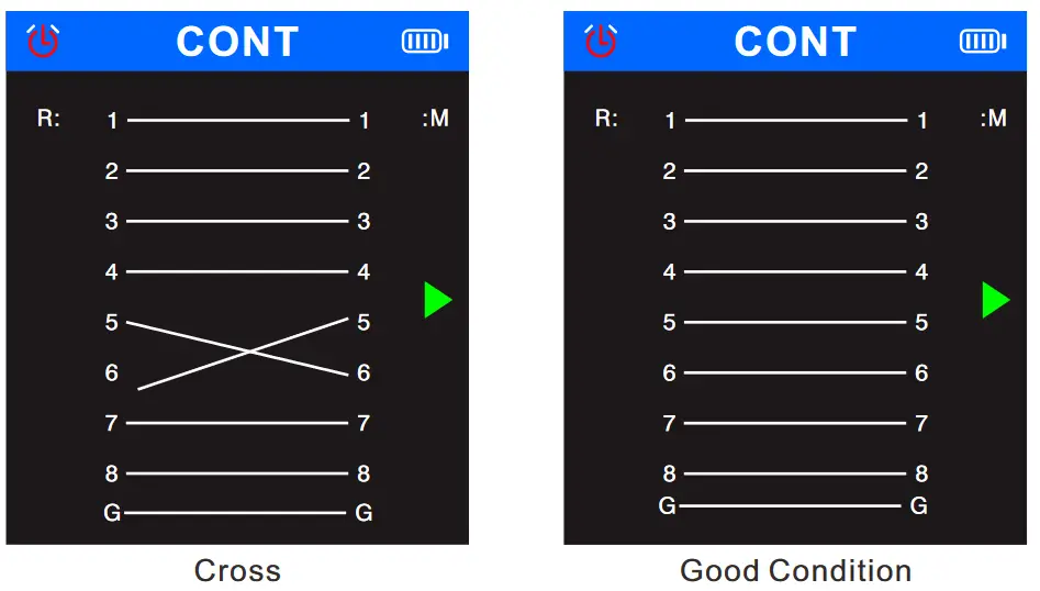
it will return to the main menu.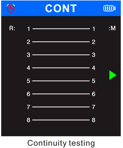 Open, short, cross,and good condition status are as follows
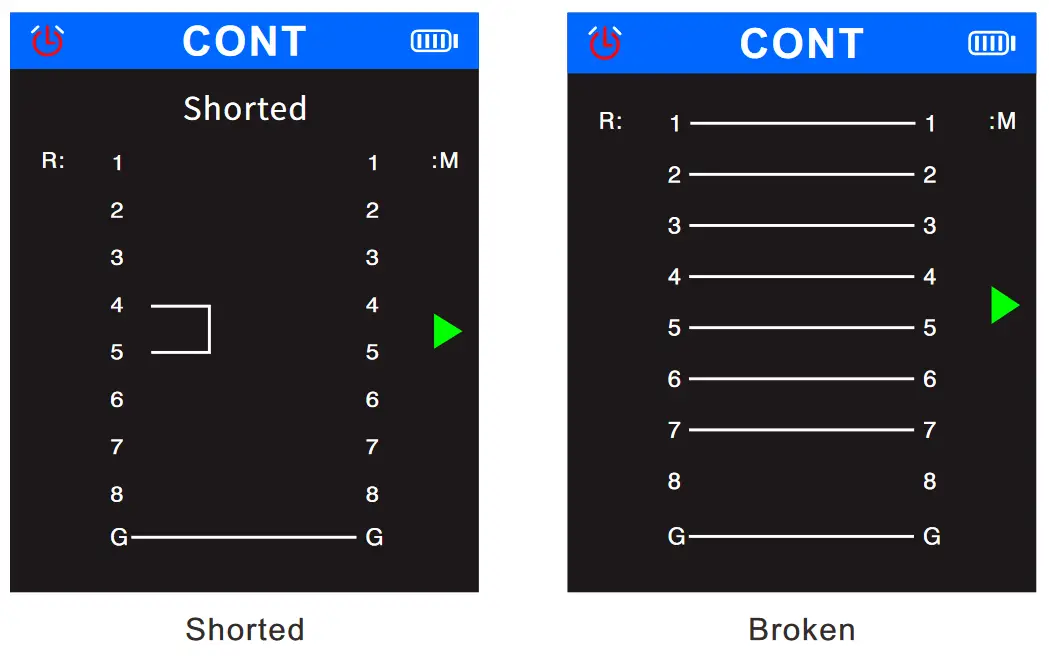
 2、SCAN
Select the ![]() in the main menu, and press the
in the main menu, and press the![]() , Enter SCAN Function.
, Enter SCAN Function.
Screen displays two options of “Digital Model” and “Analog Mode”, you can press the ![]() or
or ![]() to choose scan mode, the
to choose scan mode, the ![]() triangle arrow indicates the current function, and the
triangle arrow indicates the current function, and the ![]() triangle arrow indicates the current position where the cable needs to be inserted.
triangle arrow indicates the current position where the cable needs to be inserted.
Click ![]() or
or ![]() to return back the main menu.
to return back the main menu.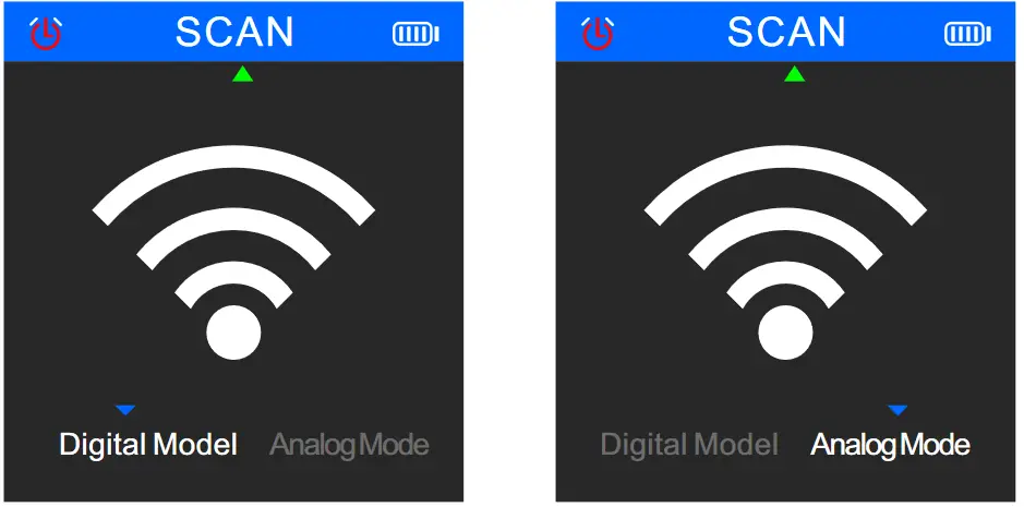 Two scan modes selectable: AC filter mode/Analog mode, up to 300m.
3、Flash
Select the![]() in the main menu, and press
in the main menu, and press![]() the to enter the port flashing function. The screen displays the words “Link test..”, and the
the to enter the port flashing function. The screen displays the words “Link test..”, and the![]() triangle arrow indicates the current
triangle arrow indicates the current
position where the cable needs to be inserted.
After finishing test, if test fails, the result will show “Time out”, maybe the cable is not plugged in properly or other reasons. If the test is successful, it will display the specific information of the current switch (FDX: full duplex / HDX: half duplex) Protocol (Auto-Nego / Non-Auto-Nego).
And the two lights of the two ports will also flash at the same frequency. The circle in the screen will also flash with the port light, moreover, the solid circle and the hollow circle will flash synchronously.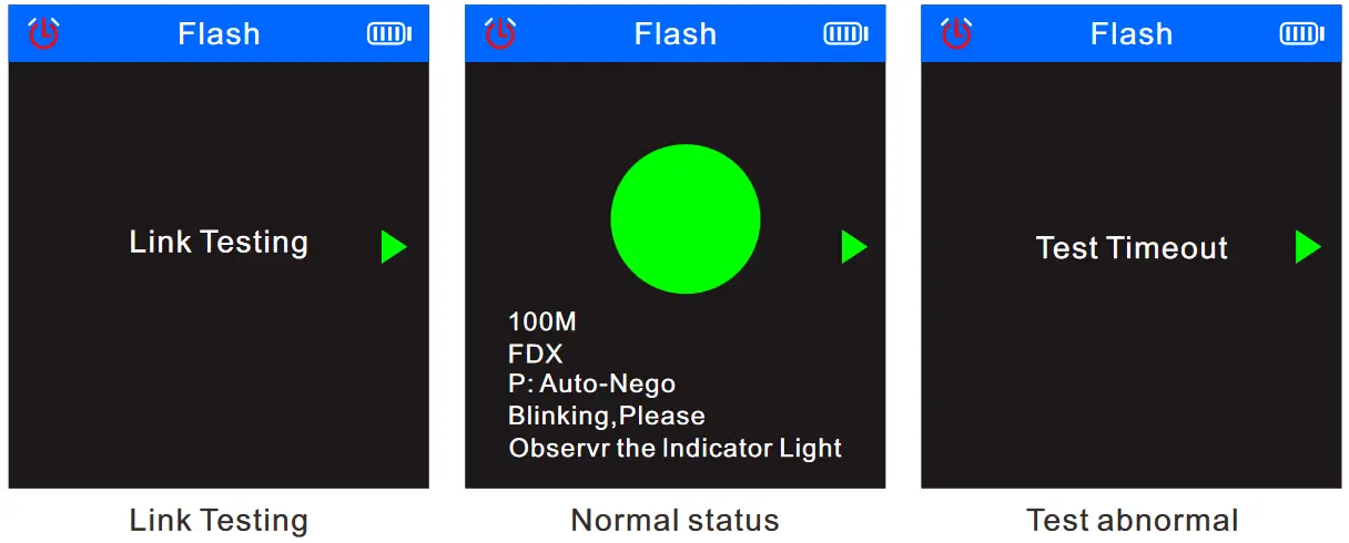 Hub blink for locating network port by the flashing port light on Hub / Switch. Available to 10M/100M/1000M Hub/ switch.
4、Length
Select the ![]() in the main menu, and press the
in the main menu, and press the![]() to enter the length test function.
to enter the length test function.
When test the cable length, press ![]() to switch the cable type: Cate5 or Cate6.Press the
to switch the cable type: Cate5 or Cate6.Press the ![]() or
or ![]() to select the unit, and then press the
to select the unit, and then press the![]() to switch back and forth between the units (m/yard/feet). The
to switch back and forth between the units (m/yard/feet). The![]() triangular arrow indicates the current position where the cable needs to be inserted. If a certain cable is abnormally short, it will be indicated by a red line pattern.
triangular arrow indicates the current position where the cable needs to be inserted. If a certain cable is abnormally short, it will be indicated by a red line pattern.
When test the cable lenght, you can switch the cable types according to following figure: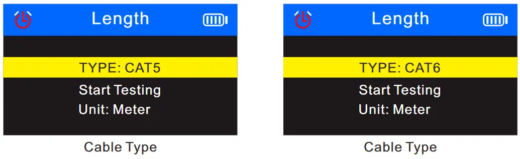 The measurable cable lengths are:
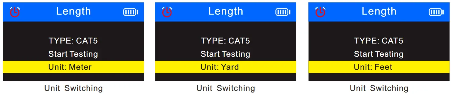 The screen display of length test function is as follows:
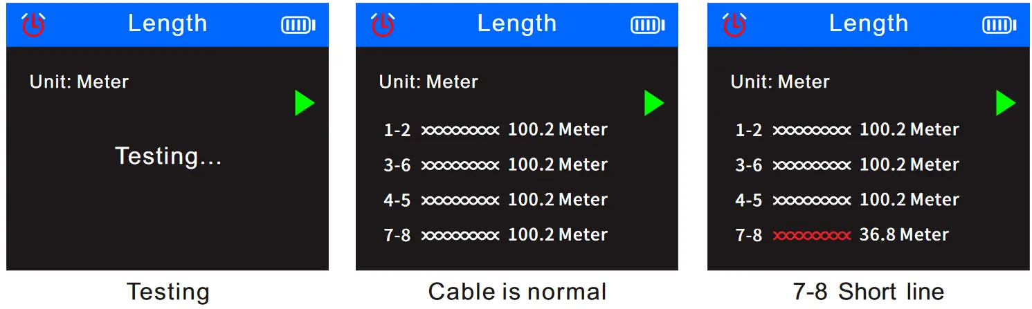 Measure cable (cat5/6) length accurately,the range is 2.5~200m.
5、PoE test
Select the ![]() in the main menu, and press
in the main menu, and press![]() the to enter the POE function test. The triangular arrow indicates the current position where the cable needs to be inserted. Press the
the to enter the POE function test. The triangular arrow indicates the current position where the cable needs to be inserted. Press the ![]() to return back to the main menu.
to return back to the main menu.
If plug and unplug the cable connected to the switch, the data will be updated automatically.
- It will display: Non-standard/IEEE 802.3af/IEEE 802.3at, when test PoE standard.
- It will display: end connection method/middle jumper method/powered by 8 cores, when judging the jumper method.
- It will display positive and negative and voltage of the PoE switch, when judging the polarity.
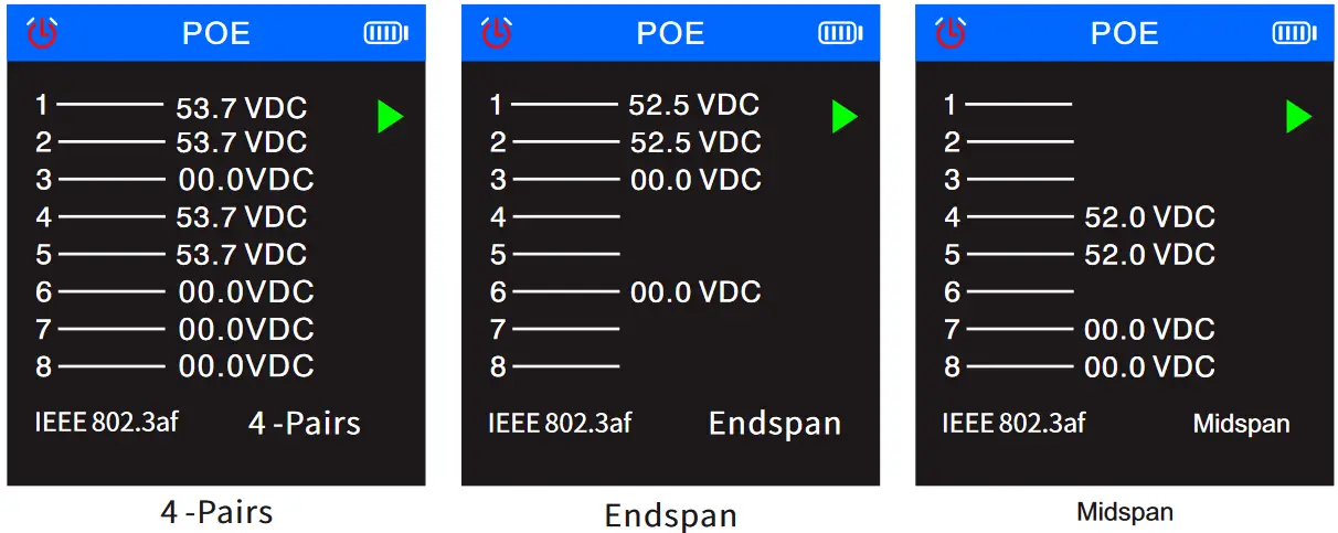
- PoE testing : identify which pins are providing power and detect how much voltage, identify which the type of PSE ( at/af standard )
6、QC testing for crystal head
Select the ![]() in the main menu, and press the
in the main menu, and press the ![]() to enter the crimping test function. The triangular arrow indicates the current position where the cable needs to be inserted, and press
to enter the crimping test function. The triangular arrow indicates the current position where the cable needs to be inserted, and press![]() the to return back to the main menu.
the to return back to the main menu.
Plug and unplug the cable testing, the result will be updated automatically. √ indicates that the channel is normal, and X indicates that the channel is abnormal.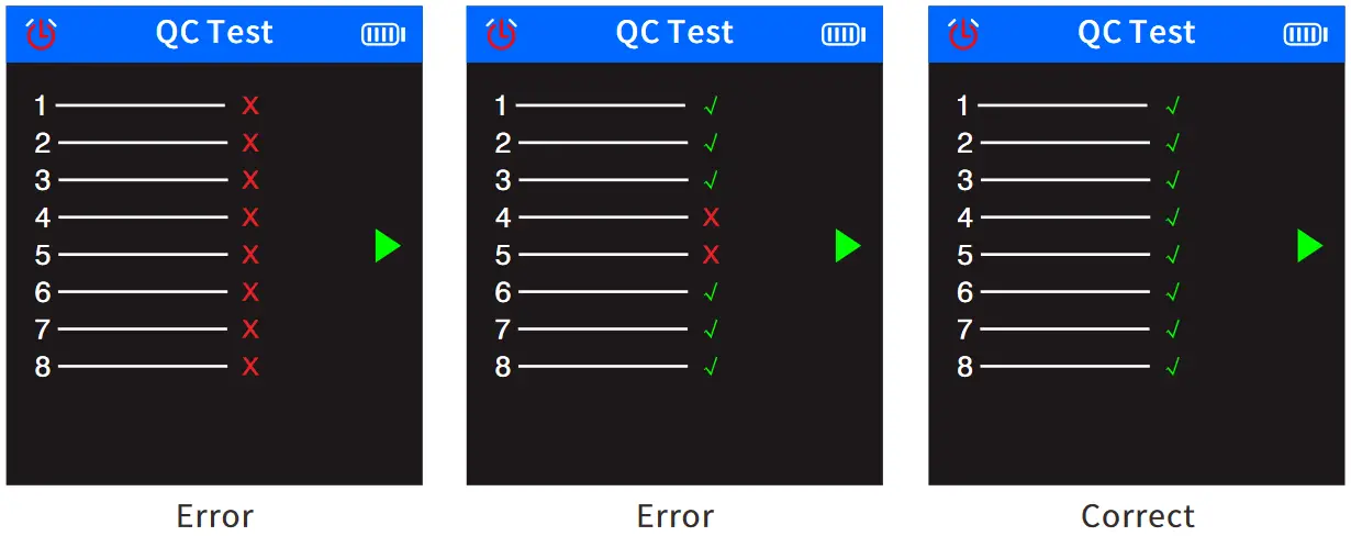 7 , Optical power meter
Select ![]() in the main menu, and press
in the main menu, and press![]() the to enter the optical power meter function.
the to enter the optical power meter function. ![]() The triangular arrow indicates the current position where the cable needs to be inserted, and the data can be updated in real time. Press
The triangular arrow indicates the current position where the cable needs to be inserted, and the data can be updated in real time. Press ![]() return back to the main menu.
return back to the main menu.
The optical power meter can test the optical power and the attenuation value of the light. The white triangular arrow indicates the current selection item. From top to bottom, the top means the unit can be switched and the bottom means the wavelength can be switched.
- Unit switching: can switch as dBm, dB, or mw, uw, nw
- Wavelength switching: Enter the option, Click OK then you can switch the wavelength to 850nm, 1300nm, 1310nm, 1490nm, 1550nm, 1625nm.
- REF Switch
REF is used to test the attenuation value of light, insert the port of the unattenuated end under this option, long press to save the current unattenuated optical power and display the value in the blue display area on the first line of the user area, then plug the interface of the attenuation end into the test end, and click the OK button in this mode to switch the user area. The blue display area on the first row displays the attenuation value or the normal optical power data.
When you use ![]() meter funcation, can press the
meter funcation, can press the ![]() or
or ![]() to select the “unit” item, press the
to select the “unit” item, press the![]() to switch the unit, select the “wavelength” item to switch the length of the wavelength.
to switch the unit, select the “wavelength” item to switch the length of the wavelength.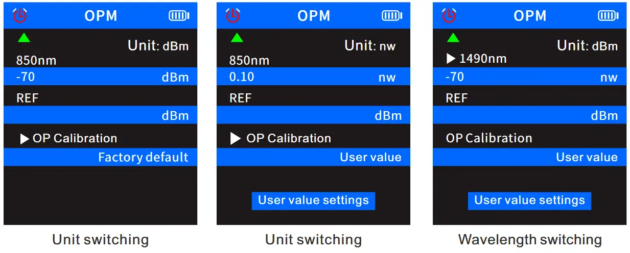
![]() When you use meter function, can press the
When you use meter function, can press the ![]() and
and ![]() to select the”User value setting” item, press
to select the”User value setting” item, press ![]() the to open the user value, press the
the to open the user value, press the ![]() again, then select the “optical power” to be set, and press the
again, then select the “optical power” to be set, and press the ![]() and
and ![]() to set the optical power ± numerical value. Press the
to set the optical power ± numerical value. Press the ![]() to return to the main menu.
to return to the main menu.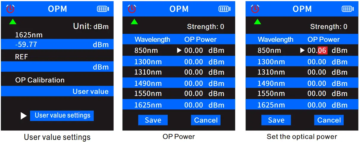 When use
 ![]() function, press the
function, press the![]() and
and![]() , select the “REF” item, and press the
, select the “REF” item, and press the![]() , the blue area on the first row displays the real-time attenuation data, and the blue area on the second row displays the previously saved unattenuated optical power. At this time, the unit is Forced to dB, and cannot be switched to other units. Press the
, the blue area on the first row displays the real-time attenuation data, and the blue area on the second row displays the previously saved unattenuated optical power. At this time, the unit is Forced to dB, and cannot be switched to other units. Press the ![]() to return to the main menu.
to return to the main menu.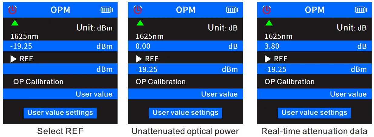
![]() Under the non-attenuation function, the blue display area on the second row of the user area will not display the value, and the blue display area on the first row of the user area will display normal optical power data.
Under the non-attenuation function, the blue display area on the second row of the user area will not display the value, and the blue display area on the first row of the user area will display normal optical power data.
8 ,VFL
Select ![]() the in the main menu, and press the
the in the main menu, and press the ![]() to enter the VFL function test. The triangular arrow indicates the current position where the cable needs to be inserted. Press the
to enter the VFL function test. The triangular arrow indicates the current position where the cable needs to be inserted. Press the ![]() to return to the main menu.
to return to the main menu.
Under this function, press![]() the to switch the red light to: fast flashing, slow flashing, and always on.
the to switch the red light to: fast flashing, slow flashing, and always on.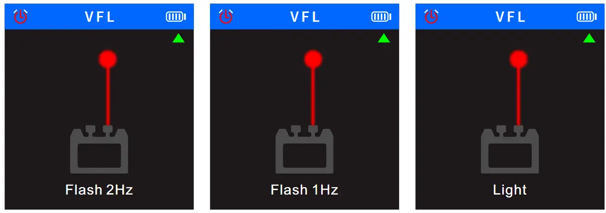 9、Setting
Select ![]() the in the main menu, and press the
the in the main menu, and press the![]() to enter the setting function, press the
to enter the setting function, press the ![]() and
and ![]() to switch options up and down, press the
to switch options up and down, press the![]() again to switch various modes of the current option, and press the
again to switch various modes of the current option, and press the![]() to return to the main menu.
to return to the main menu.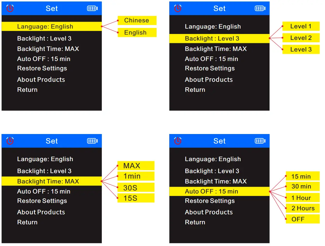
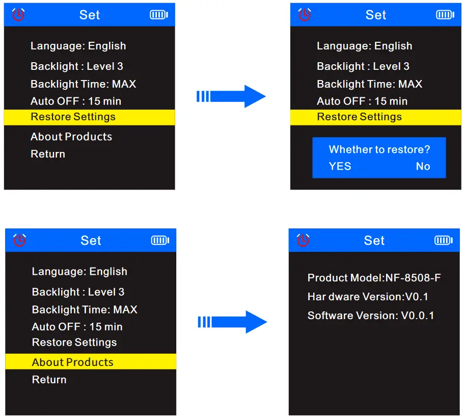 In the
 ![]() menu, select”Return” and press the
menu, select”Return” and press the ![]() , Return to the main menu.
, Return to the main menu.
Receiver
- Power
Press and hold the in the off state, and hear a beep to indicate that it has been turned on. At this time, the power indicator lights up green and the scan indicator lights up red, it means it’s in anti-jamming method; if the device turns on, long press button, it will turn off and all the lights will be off.
 - SCAN
When the receiver scans, you can press the button to switch “anti-jamming mode” or ” normal mode” . When the scan indicator is always on red, it means it is in the “anti-jamming” function. When the indicator is red and flashes r, it means it is in the “normal mode” function.
 - NCV
When the receiver turns on, press the , the NCV indicator will light up in green, meaning that the receiver is in NCV function.
 - LAMP
When the receiver turns on, press the to control the lighting to turn on or off.
 - SEN
When scan, you can adjust the sensitivity of the receiver: Rotate clockwise to increase the sensitivity, and rotate counterclockwise to decrease the sensitivity. - Type-C Charging
In the charging state, the power indicator will light red, and the red light will turn off when fully charged。
Product Specifications
| Model | NF-8508 | |||
| Cable type | CATS/CAT6 | |||
| Voltage | 60V | |||
| Battery | Type-c charging | |||
| Transmitter | CONT | Wiremap Port | RJ45 | |
| Remote Continuity | ≥ 300m | |||
| Cable sequence and faulttest | ||||
| STP/NTP | ||||
| Short circuit reminder | ||||
| Cable Scan | Anti-jamming and Normal mode | |||
| Audio transmission frequency | 455KHz | |||
| Audio transmission distance | RJ45 300m | |||
| Port Flash | Full duplex / Half duplex | Automatic Identification | ||
| Auto-Nego/ Non-Auto- Nego | ||||
| 10m/100m/1000m | ||||
| Length Tester | ≤ 20M +/-1.6M, 20M-100M +/-2.4M, ≥ 100M +/-3.2M | |||
| PoE Test | Standard/Non standard | |||
| End connection /Middle jumper/ Powered by 8 cores | Automatic Identification | |||
| PoE Power supply | Voltage detection | |||
| NVL | 10Mw | |||
| Power meter | 850/1300/1310/1490/1550/1625 ( Wavelength ) | |||
| Crimping | RJ45-8 Cores,Min length is 10cm | |||
| Low voltage prompt | Below 3.5V ± 0.1V power indicator flashes | |||
| Power supply | 3.7V 1500mAh Polymer lithium battery | |||
| Transmitter size | 148 X 70 X32 mm | |||
| Receiver | Sensitivity adjustment | |||
| No-load shielded network cable/non-empty shielded network cable 300M | ||||
| Anti-jamming and Normal mode | ||||
| Scan current | ≤ 5.300mA | |||
| Remote Continuity | ≥ 300m | |||
| NCV detection function | ||||
| Lamp | ||||
| Low voltage prompt | ||||
| Power supply | 3.7V 1500mAh Polymer lithium battery | |||
| Receiver size | 198x 50 x 28 mm | |||
Product application field
- Telecommunication bureau/Internet cafe/telecommunication engineering company, network engineering company/power force and other weak current projects, line maintenance and other departments that require metal lines.
- Telecommunication network line engineering and general maintenance work; computer network line engineering; other metal conductor line engineering and maintenance work.


Accessories
| Transmitter | 1pc |
| Receiver | 1pc |
| Type-c data cable | 1pc |
| Earphone | 1pc |
| RJ11 adapter line | 1pc |
| Quality certificate | 1pc |
| Cable adaptors | 1pc |
| RJ45 adapter line | 1pc |
| User manual | 1pc |
| Carry bag | 1pc |
| Color box | 1pc |
Note: Please refer to the actual product received.![]()
![]()


