![]()
 NF-8508 Optical Wire Meter Tracer
User Manual
![]()
VER:V1
Optical Wire Meter Tracer
![]() Read the precautions before your operation
Read the precautions before your operation
The transmitter and receiver of this device are powered by lithium polymer batteries.
Please do not place the device in a location that is dusty, humid, or hot (above 40°C).
Please do not disassemble the device. Repair and maintenance shou Id be done by a professional staff.
When not using the device for a long time, please remove the battery to prevent the battery liquid from leaking out.
Please do not perform related operations on the communication line during thunderstorms to prevent lightning strikes and personal safety.
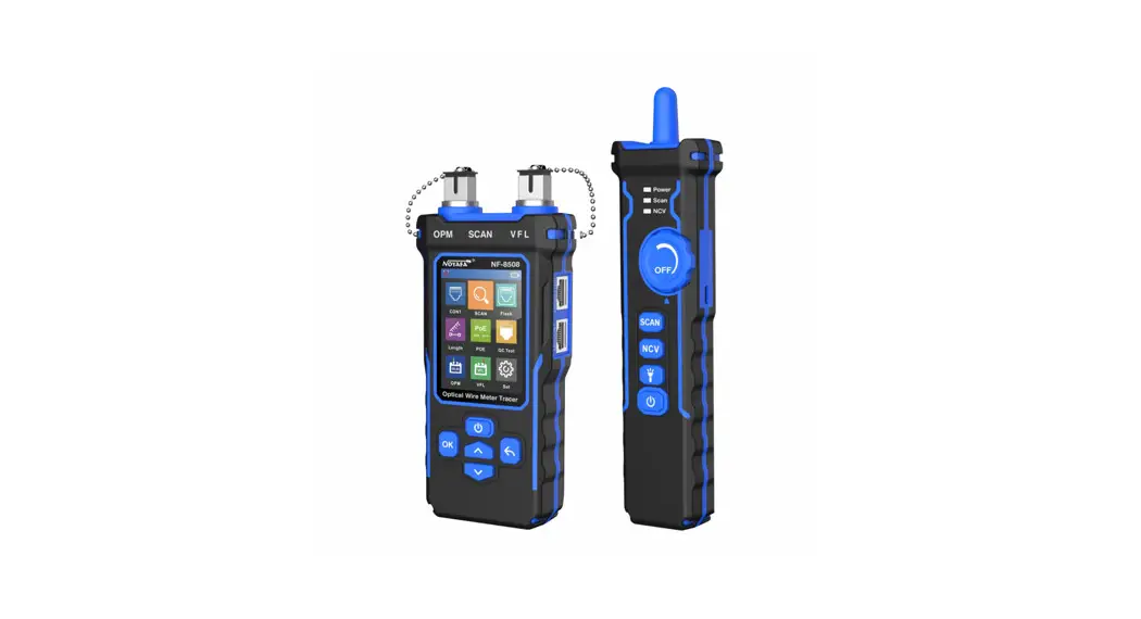
NF-8508 is an Optical wire meter tracer for home and public facility network cable repair.
Its main functions includes Multi-Function Network Cable Tester (cable faults testing, cable length measurement, PoE testing, port flash, Crystal head QC test function) and optical power meter & Visual Fault Locator function. Also it has two modes for options to track cable like Digital mode & Analog mode, all these makes it a must-tool for cabling engineers.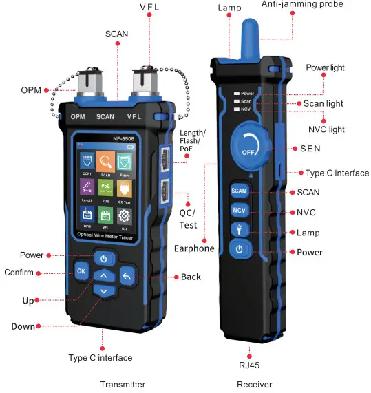
Auto power off icon
![]() When this icon is displayed it means that the auto power off function is on and when this icon is not displayed it means that the auto power off function is off.
When this icon is displayed it means that the auto power off function is on and when this icon is not displayed it means that the auto power off function is off.
Power display icon![]() Displays the current power and charging status, green charging status, but white means non-charging status.
Displays the current power and charging status, green charging status, but white means non-charging status.
| CONT | SCAN | Flash |
| Length | PoE | QC Test |
| OPM | VFL | Set |
Product function instructions
Transmitter
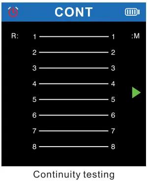
- Continuity testing
Connect one cable end to “QC/TEST” port of the transmitter on the right side, and the other end connect “RJ45” port of the receiver on the bottom.Select in the main menu, and press▲it will show the cable types, then press
 the screen will show the test result, the A triangle indicates the position to be plugged in.
Clickagain, it means test again and the result will show again. Click  can return to the main menu.
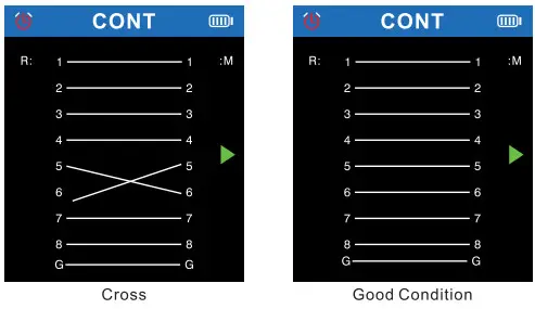
 Open, short, cross,and good condition status are as follows
 SCAN
SCAN
1.Connect the cable to be tested to “SCAN” port of transmitter on the top, enter” “in the main menu, press
  or
or to choose scan mode you prefer, digital mode or analog mode, then set the corresponding mode on receiver accordingly. After that, hold the receiver to locate cable at the other end, the loudest voice is the correct one.
The ▼ytriangle arrow indicates the current function, and the▲triangle arrow indicates the current position where the cable needs to be inserted.Clickor to return the main menu.
Two scan modes selectable: Digital mode/Analog mode, up to 300m.
Attention: If the transmitter is in digital scan mode, the receiver must be in digital mode. the analog scan in transmitter matches analog mode in receiver.
If the modes are not matched correctly, even the receiver touch the correct cable, it won’t generate tone, either.
- Port flash
Connect one cable end to the “Length/Flash/PoE” port of the transmitter on the right side, select the in the main menu, and press to enter the port flash function.
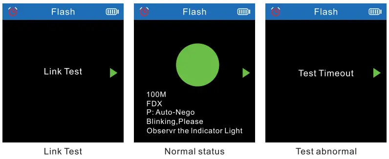
The screen displays the words “Link test..”, and the ►triangle arrow indicates the current position where the cable needs to be inserted.
If test successfully, the screen will display the green circle and the specification of the current switch (FDX: full duplex/ HDX: half duplex) Protocol (Auto-Nego / Non-Auto- Nego).
The circle, and the port on the router (or switch) will flash, if there is a port whose flash frequency is same as the circle on transmitter, the frequency is around 3 secs, also the other ports are flashing more quickly, then you can easily identify it is your target port. But if test fails, the screen will display “Test Timeout”, maybe because the cable is not plugged in properly.
And the two lights of the “Length/Flash/PoE” port will also flash at the same frequency. The circle in the screen will also flash with the port lights, moreover, the solid circle and the hollow circle will flash synchronously. Hub blink for locating network port by the flashing port light on Hub/ Switch. Available to 1 0M/1 00M/1 000M Hub/ switch.
 - Length
Connect one end of cable to “Length/Flash/PoE” port,disconnect the cable at far end, choose on the main menu, and select the cable type and unit (meter/ yard/ feet) before testing.
Choose “Start Testing”to press to measure and the result will show on the screen. Test images and results
The► triangle arrow indicates the current position where the cable needs to be inserted.
If the cable is short or broken, the the data will be red.
1. The Ian cable to be tested must be de-energized.Available length units
2. Disconnect the cable at the far end, no other devices connected!
3. The range must be 2.5m-200m, otherwise, it would be display 0 meter.
Available cable types Available length units
 Test images and results
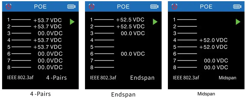
- PoE test
It can test the information of standard PoE device, such as POE voltage, power supply polarity, power supply mode and also the type of PSE(af or at standard). If the PoE device is non-standard, it can also test POE voltage, power supply polarity, power supply mode, but it can’t tell the type of PSE, just display “Non standard” Connect the cable into”Length/Flash/PoE”port, the testing result display as below image. Attention:
1.If all the 8 pins are providing power, it won’t display polarity.
2. If connected with PoE device, the result can be displayed after a few secs, it there is no result displayed after 30secs, then the device connected may not be PoE device. - QC testing for crystal head
Connect one of cable end to the “QC/TEST” port.Select in the main menu, and press to start test.
► The triangular arrow indicates the current position where the cable needs to be inserted, and press can return to the main menu.
Plug and unplug the cable tested, the result will be updated automatically. ✓ indicates that the channel is normal, and X indicates that the channel is abnormal.
- Optical power meter
The optical power meter can test the optical power and the attenuation value of the light.
Insert one end of fiber cable into 0PM port,select in the main menu, and press to enter the optical power meter function.
▲The triangular arrow indicates the current position where the cable needs to be inserted, and the data can be updated in real time. Pressreturn to the main menu.
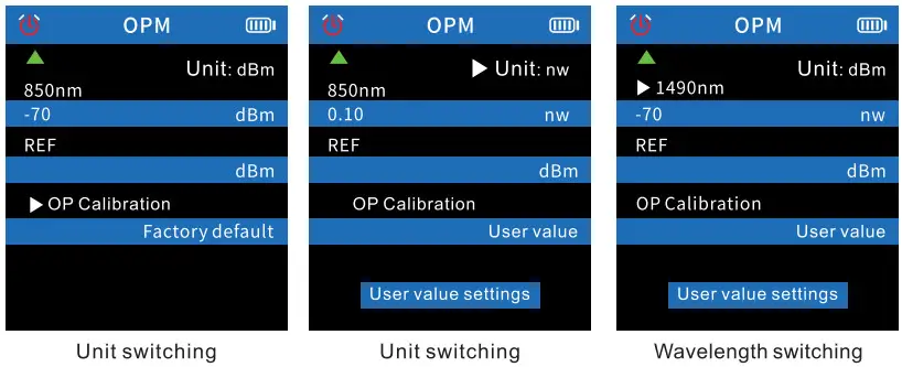
The icon indicates the current selection item. From top to bottom, the top means the unit can be switched and the bottom means the wavelength can be switched.
(1)Available Unit: dBm, dB, or mw, uw, nw
(2) Available Wavelength: 850nm, 1300nm, 1310nm, 1490nm, 1550nm, 1625nm.
Insert one end of the fiber cable end into OPM port, choose the unit and wavelength you needed before test.
(3) REF Switch
REF is used to test the attenuation value of light. After testing the optical power, pressor to select REF, when the iconis te font of REF, long presskey to
automatically save the current optical power value to be the second blue area, which means that you have saved the test reulst of measured optical power this time. When measure again, you can compare the previous result with current result to know the attenuation value of the device testing.
Pess the iconor can switch Unit, Wavelength. When the icon in the front of the certain item, means can switch them through pressRefer below operation pictures. Pess the icon orcan select the”User value setting” .Presssetting, press again to start set the “optical power”, press and to (increase to open User value or decrease) numerical value. Press return to the main menu.
 Press the icon or can select the REF, when the iconisthe front of REF, long press can automatically save the current data of optical power to be in first blue area.
At this time, the unit is forced to dB, and cannot be switched to other units. Press return to the main menu.
 Without in REF function, the blue display area on the second row of the user area will not display the value, and the blue display area on the fifirst row of the user area will display normal optical power data.
 - VFL
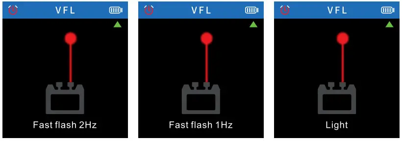
Insert one end of fber cable into the VFL port,select in the main menu, and pressto sart test. ▲The triangular arrow indicates the current position where the cable needs to be inserted. Pressto return to the main menu.
Presscan switch three modes· Fast falsh, Slow falsh and Light.
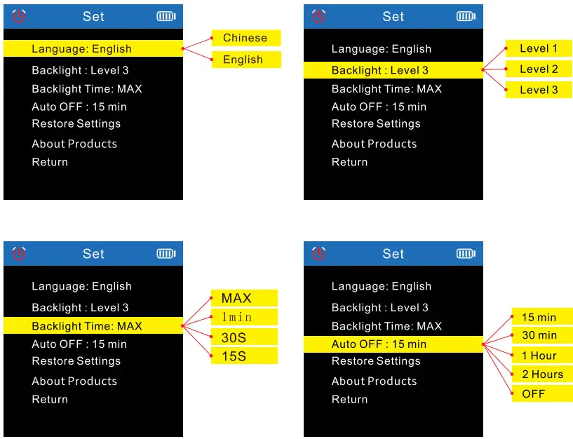
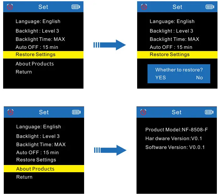
- Setting
Select in the main menu, and press to enter the setting function, press andto switch options up and down, press again to switch various modes of the current option, and press to return to the main menu.
 In themenu, select” Return” and press the . Return to the main menu.
 Open, short, cross,and good condition status are as follows
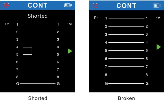
 SCAN
SCAN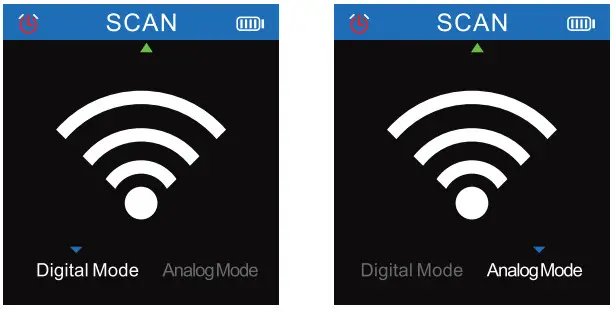
 Hub blink for locating network port by the flashing port light on Hub/ Switch. Available to 1 0M/1 00M/1 000M Hub/ switch.
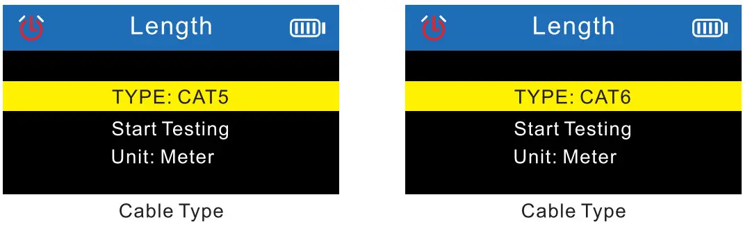 Available length units
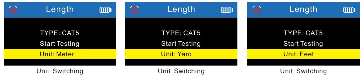 Test images and results
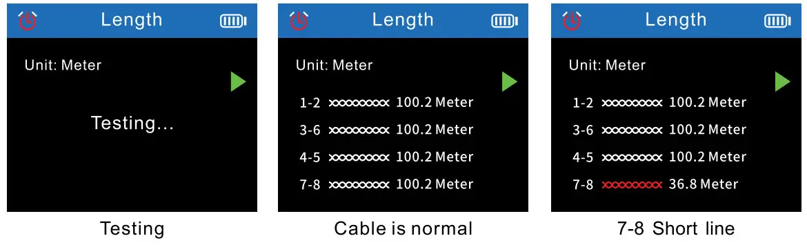
 Attention:
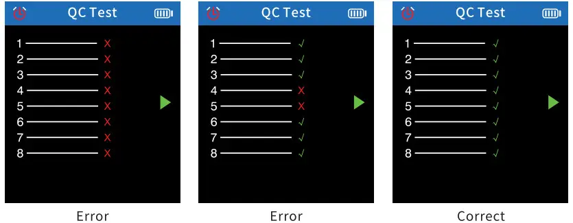
 Pess the icon
 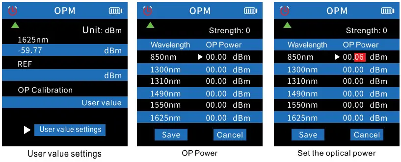 Press the icon
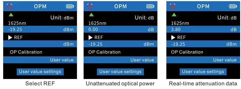
 In the
Receiver
- Power
Long press hear a beep, it means the device has been turned on. At this time, the power indicator lights up green and the scan indicator lights up red, the default is digital mode.
Long press power button, it will turn off and all the lights will be off. - SCAN
When the receiver turns on, press scan the can switch “digital mode” or “analog mode”.
Scan indicator is red, means it is digital mode. Scan indicator flashes red, means it is analog mode. - NCV
When the receiver turns on, press nvc the NCV indicator lights green, means NCV function turns on. - Lamp
When the receiver turns on, press light to control the light to turn on or off. - SEN
When scan, can adjust the sensitivity of the receiver to track the cable. Rotate clockwise to increase the sensitivity, rotate counterclockwise to decrease the sensitivity. - Type-C charging
The power indicator lights red, means it is charging, the red light turns off means it is fully charged.
Product Specifications
| Model | NF-8508 | |||
| Cable type | CATS/CAM | |||
| Voltage p otection | 60V | |||
| Battery | Type C charge | |||
| Transmitter | CONT | Wiremap Port | RJ45 | |
| MAX range | 300m | |||
| STP!NTP | ✓ | |||
| Digital mode and Analog mode | ✓ | |||
| Scan | Frequency | 455KHz | ||
| Port Flash | Full duplex/ Half duplex | Automatic Identification | ||
| Auto-Nego/Non-Auto-Nego | ||||
| 10m/100m/1000m | ||||
| Length | ≤20M+/-1.6M, 20M-100M+/-2.4M, ≥100M+/-3.2M | |||
| PoE | Standard/Non standard | Automaticldentification | ||
| End connection /Middlejumper/ Powered by 8 cores | ||||
| PoE Power supply | Voltage detection | |||
| NVL | 10Mw | |||
| Power meter | 850/1300/1310/149011550/1625( Wavelength ) | |||
| Crimping | RJ45-6Cores,Min length is 210cm | |||
| Lower voltage warning | < 3.5V ± 0.1V | |||
| Power supply | 3.7V 1500mAh Polymer lithium battery | |||
| Transmitter size | 148 X 70 X32 mm | |||
| Recevier | Sensitivity adjustable | ✓ | ||
| MAX range | 300m | |||
| Digital mode and Analog mode | ✓ | |||
| MAX working current | ≤300mA | |||
| NCV | ✓ | |||
| Lamp | ✓ | |||
| Lower voltage warning | ✓ | |||
| Power supply | 3.7V 1500mAh Polymer lithium battery | |||
| Receiver size | 198 x 50 x 28 mm | |||
Product application field
- Telecommunication bureau/Internet cafe/telecommunication engineering company, network engineering company/power force and other weak current projects, line
maintenance and other departments that require metal lines. - Telecommunication network line engineering and general maintenance work; computer network line engineering; other metal conductor line engineering and maintenance work.

Accessories
| Transmitter | 1 pc | Alligator clip adaptor | 1 pc |
| Receiver | 1 pc | RJ45 Adaptor cable | 1 pc |
| USB Type-C cable | 1 pc | User manual | 1 pc |
| Earphone | 1 pc | Carry bag | 1 pc |
| RJ11 adapter line | 1 pc | Color box | 1 pc |
| Quality certificate | 1 pc |
Note: Please refer to the actual product received.


