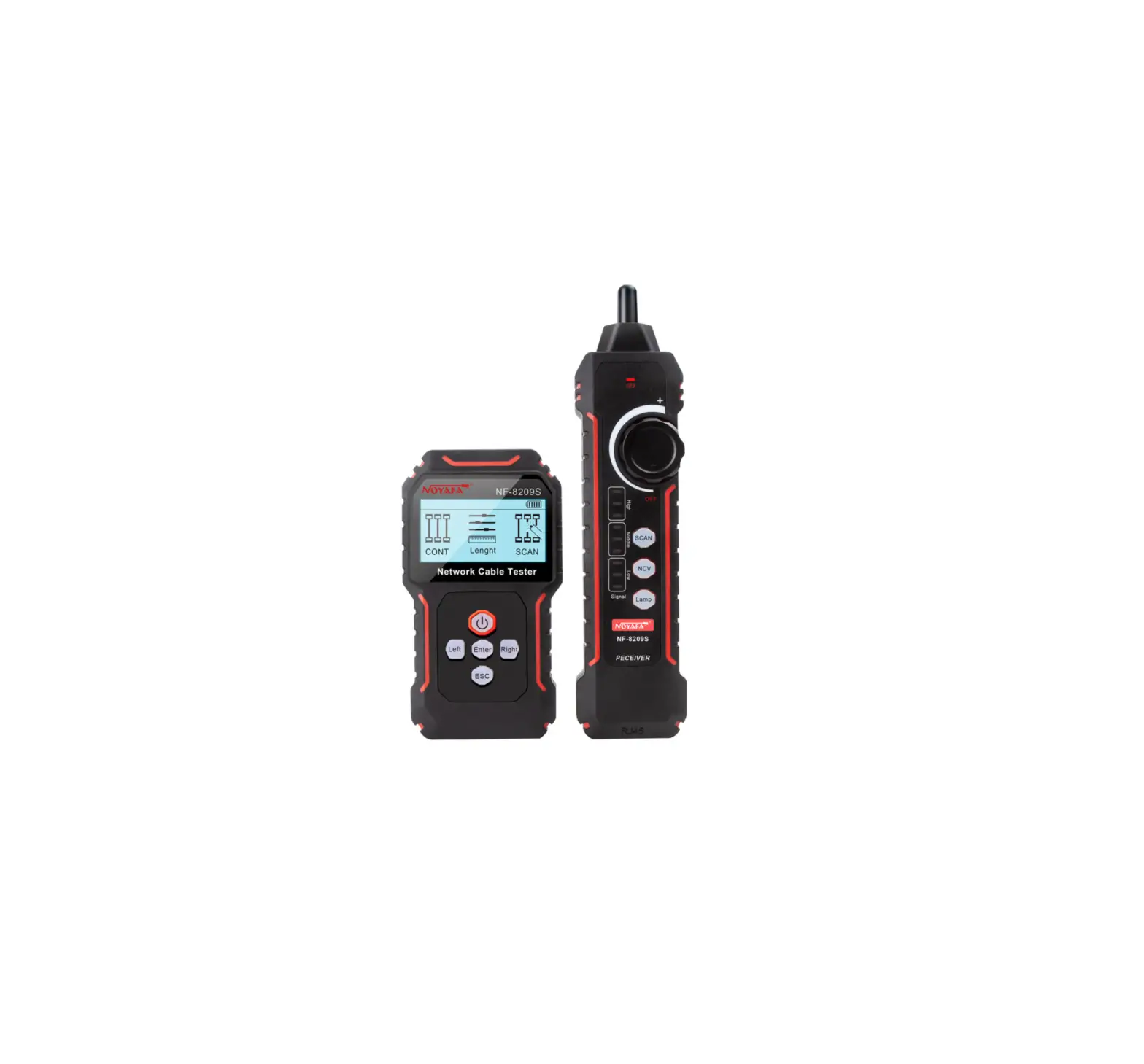
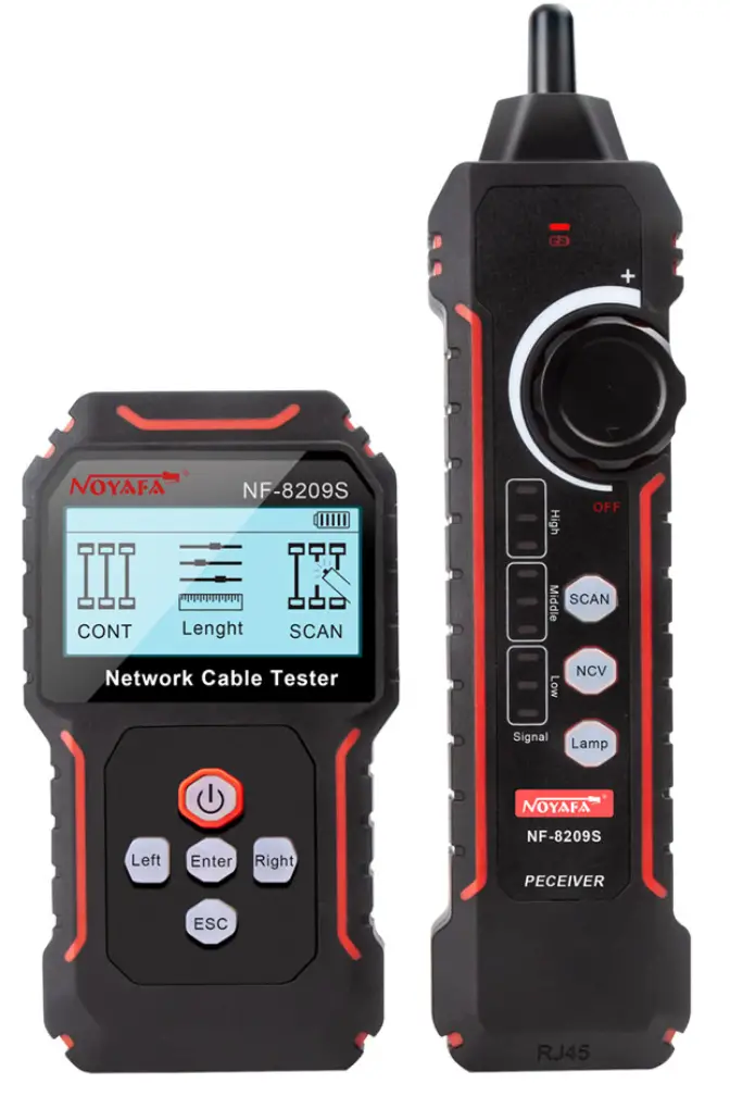
NOYAFA NF-8209S Network Cable Tester
Safety Instruction
 Read the precautions before your operation
- This device is powered by a lithium polymer battery.
- Do not expose this product to direct sunlight for long periods of time.
- Please do not disassemble this product, repair, maintenance matters should be professional personnel.
- The transmitter of this equipment has automatic shutdown function, and the automatic shutdown time can be set according to the user’s needs (the receiver has no automatic shutdown function).
- If you do not use this device for a long time, it is recommended to charge the device once every other time.
- The device cannot be connected to a live line that exceeds the protection voltage (such as a 220V power supply line).
- Do not operate communication lines during a thunderstorm to prevent personal safety from being affected by lightning.
Overview
NF-8209s network cable tester, new anti-interference line finding scheme using digital signal receiving and decoding technology, anti interference degree is higher, more accurate, eliminate false positives. At the same time, it has the functions of common line finding, anti-interference line finding, continuity testing, length testing, PoE testing, port flashing, QC testing, NCV function, etc, which can meet users’ needs to a greater extent and improve work efficiency.
Part Of The Function Description
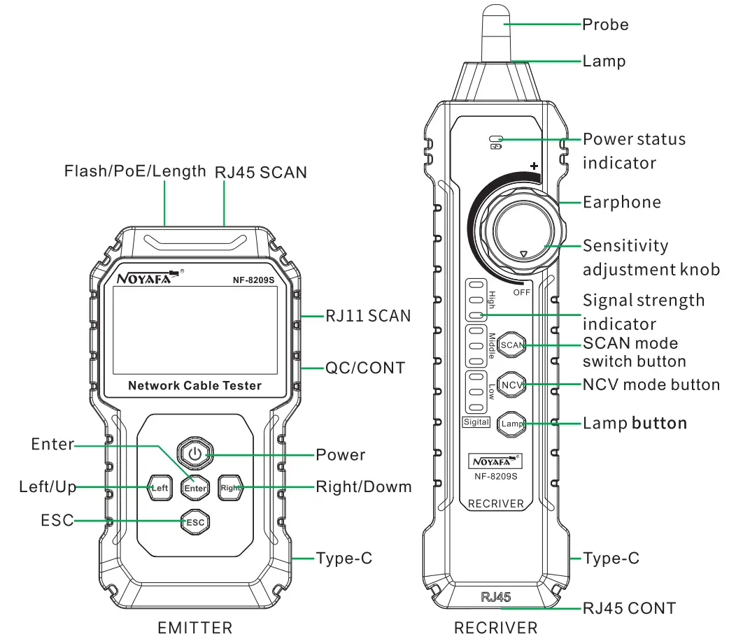
Main Interface Of Transmitter
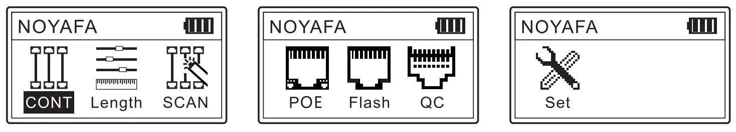
Product Features Overview
- CONT Test: Cross, short circuit, open circuit, normal.
- Length test: Test the network cable length breakpoint without calibration.
- SCAN Mode: Normal mode/anti-interference mode.
- PoE Test: The power supply voltage of the power supply wire core is monitored. Both standard and non-standard PoE can be measured.
- Port Flash: Quickly locate the network cable on the switch or router.
- QC Test: Test whether the crystal head is properly pressed.
Operating Instructions
Switch machine
Emitter: Long press the power button to turn on; long press the power button to power off in the power-on state.
Receiver: Turn the sensitivity knob clockwise until you hear a “click” sound to turn on; in the power-on state, turn the sensitivity knob counterclockwise until you hear a “click” sound to turn off.
Continuity testing
Test the short circuit, open circuit and cross of the network cable.
Connect one end of cable to “QC/CONT” port of transmitter on the right side, the other end to the RJ45 port of reote, Press “Enter” to start testing.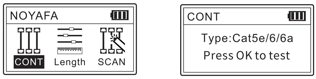
If the cable is a good one, the result will be as below.
(UTP Ian cable)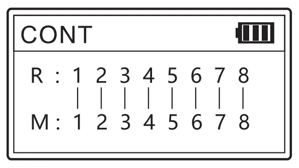
(STP Ian cable)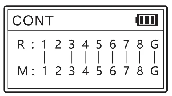
Other test results
Pin12, Pin45 are both shorted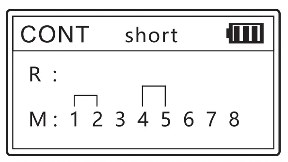
Pin5, Pin8 are broken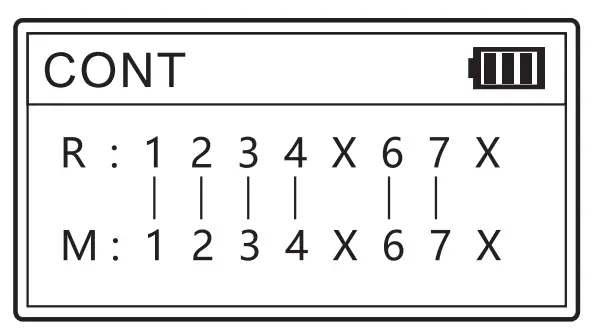
Pin56, Pin18 are cross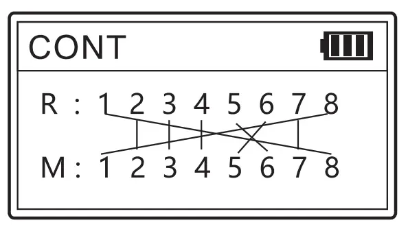
The network line is not connected or all connections are disconnected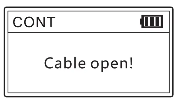
Length measurement
The length test can test the length of each twisted pair of the network cable separately and display it on the screen. When measuring the length, the network cable cannot be powered on, and cannot be connected to equipment and instruments. The length must be between 2.5 meters and 200 meters, otherwise the measurement data will be inaccurate.
There are three options in the length test interface: type, start test and unit selection. When “Type” is selected, press the OK key to switch between Category 5 and Category 6 cables cyclically. When “Start Test” is selected, press the OK button to test the length of the network cable., select the “unit” option, press the enter key to switch the length unit, and you can switch between “meter”, “yard” and “feet” cyclically.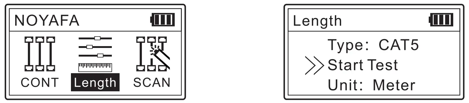
Insert one end of the network cable that needs to be measured into the end flash/PoE/length measurement socket of the transmitter. The test results are displayed in four groups, corresponding to the 12, 36, 45, and 78 pairs of the twisted pair, and the length unit displayed is the previously set unit.
Display result 1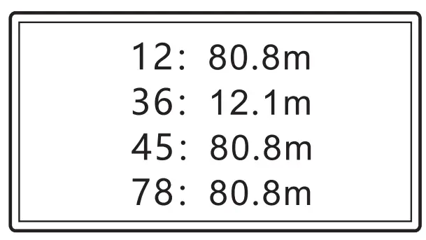
Display result 2
36 Twisted pair 12.1 m Short circuit/open circuit (Check whether it is short circuit or open circuit through the CONT Test) If the measured length is not between 2.5 and 200 meters, the test result of the twisted pair is shown as 2.
If the test fails after multiple tests, the length test hardware is damaged.
Cable scan
Insert one end of the network cable that needs to be found into the RJ45 of the transmitter (the telephone line is connected to theRJ11 interface) and select the SCAN mode, turn it on and use the receiver to find the network cable.
The closer the receiver probe is to the target line, the stronger the signal and the louder the sound.
The adjuster on the receiver is used to adjust the sensitivity when scanning.
SCAN can be divided into two modes: “Digital” and “Analog”. In the two modes, all 8 cores of the network cable connected to the SCAN port have signal transmission.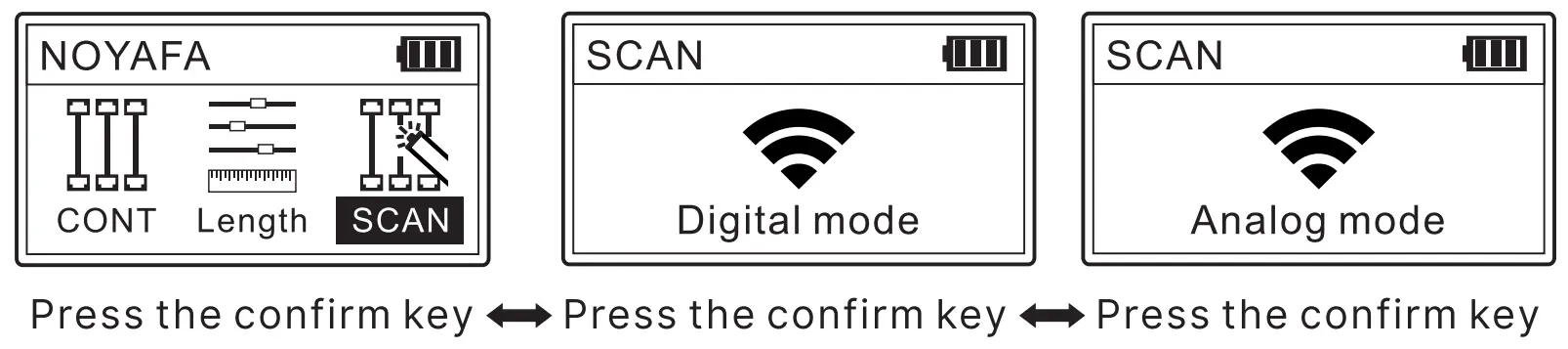
Note: The SCAN mode of the receiver should be the same as the SCAN mode of the transmitter (short press the receiver function key to switch), otherwise the signal will not be received.
PoE testing
The POE test is performed automatically. You only need to connect the device to the flashing/POE/length test port on the transmitter to display the test result.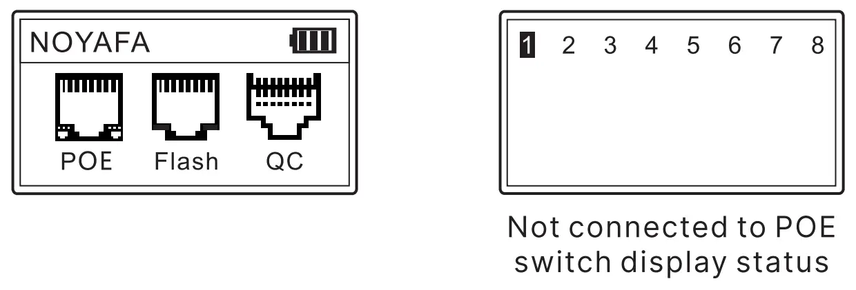
Standard PoE device
It can test the information of standard PoE device, such as POE voltage, power supply polarity, power supply mode and also the type of PSE (af or at standard).
Connect the cable into PoE” port, the testing result display as below image.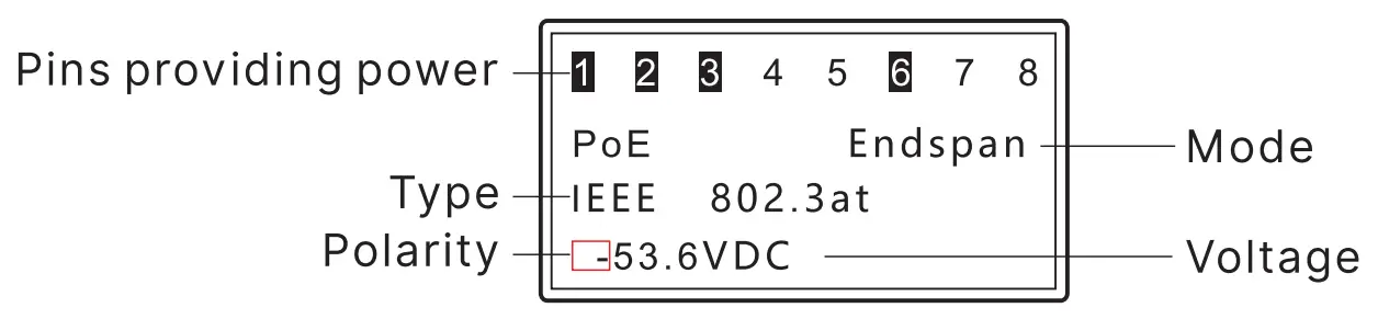
Non-Standard PoE device:
If the PoE device is non-standard, it can also test POE voltage, power supply polarity, power supply mode, but it can’t tell the type of PSE, just display “Non standard”. Connect the cable into “PoE” port, the testing result display as below image.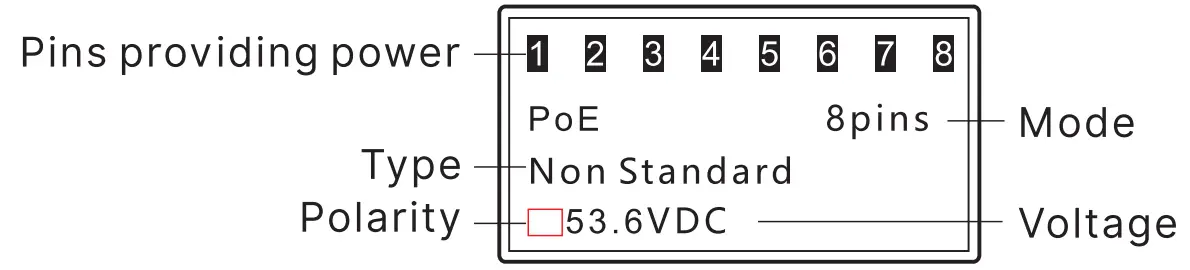
Attention: If all the 8 pins are providing power, it won’t display polarity.
If connected with PoE device, the result can be displayed after a few secs, it there is no result displayed after 30secs, then the device connected may not be PoE device.
Port Flash & Switch details testing
Connect a Ian cable to “Length/Flash”port on the main unit, choose “Flash” on the main menu to start testing. The 2 indicators on the “Length/ Flash” port will be lit and flash. Then observe the ports on switch, if there is a port whose flash frequency is 3 secs, and slower than all the other ports, it tells you the port is the target one you’re looking for.
Also, the device can tell you the connected switch’s information, such as its speed (10M/100M/1000M), transmitting modes (FDX: full duplex/ HDX: half duplex) Protocol (Auto-Nego / Non-Auto-Nego). See the graph for ref. as below.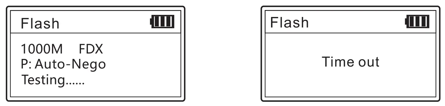
QC Testing
QC test: It is used to test whether the cable core is connected to the copper sheet of the RJ45 connector.
Insert the end of the network cable to be tested into the “QC/CONT” port of the transmitter. The QC test is an automatic test, and the result will be displayed after connecting. “v” means the QC is normal, and “X” means the QC is abnormal.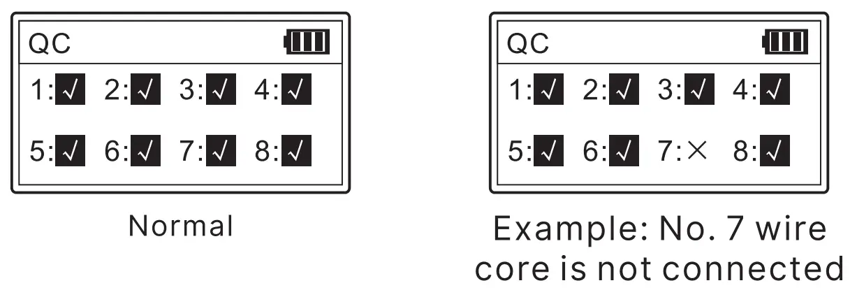
Setting
Backlight setting
Adjust the backlight time among 15s, 30s, 60s, on, and off.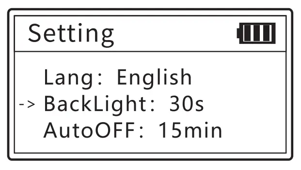
Auto-off time
Adjust the backlight time among 1 5mins, 30mins, 1h, OFF.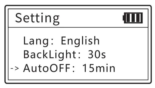
Contrast setting
Press the left and right keys to adjust the contrast to suit yourself.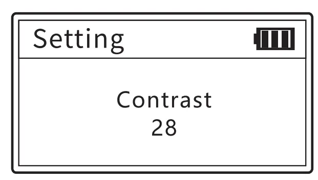
Version information
To check version information of software and hardware.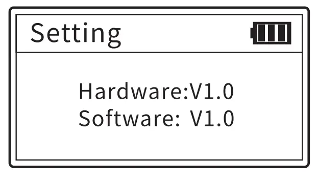
NCV function (Receiver)
The NCV function is used to detect the presence of strong electrical cables in the working environment to ensure construction safety.
Press the receiver NCV key to enter NCV mode, and the receiver emits a “beep” sound when greater than 70V AC is detected
Lighting function (Receiver)
In any interface, you can use the lighting button to control the lighting switch state. Press once to turn on the light and once to turn off the light.
Low battery warning
Both the transmitter and receiver use 3.7V 1400mAh polymer battery, which can be charged through the Type-C interface.
The power indicator on the screen flashes when the transmitter is low power.
The power status indicator flashes when the receiver is low power.
Packing list
| Emitter | 1pc | Earphone | 1pc |
| Receiver | 1pc | Cable adaptors | 1set |
| Charging line | 1pc | Carry bag | 1pc |
| Quality certificate | 1pc | User manual | 1pc |
Technical Parameters
| EMITTER | Wiremap | Cable type | CAT5/CAT6 |
| Cable sequence and fault testing | Norma l, open circuit , short circuit, cross | ||
| STP/ UTP | Distinguishable by test | ||
| MAX rang e | 600M | ||
| QC Test | Test type | 8P | |
| Response speed | ≤1S | ||
| Minimum recognition | 10cm | ||
| Length | Test line I | CAT5, CAT6 | |
| Test range | 2.5-200m | ||
| Accuracy | 20m ± 1.6m 20~100m ± 2.4m > 100m :1:3. 2m | ||
| Unit | m/ft/yd | ||
| SCAN | Cable type | CAT5/CAT6 | |
| Max. signal voltage | 5V± 1.0VP- P | ||
| Frequency | 455KHz | ||
| Dual mode | Analog/Digital mode | ||
| MAX range | 600M | ||
| POE | Voltage test range | DC5~60V | |
| Power supply core/ jumper mode | end jumper/middle jumper / 8-c ore power supply / unknow | ||
| PSE type | non – standard, IEEE802.3at/ af | ||
| Flash | Full-duplex and half duplex identification | Yes | |
| Auto – Nego/ Non- Auto – NE/got | Yes | ||
| Switch type | 10M/100M/1000M | ||
| LCD display | 128* 64 Dot-matrix with backlight | ||
| Language display | Chinese / English | ||
| Key s | 4 functions +1 power butt on | ||
| Ports | Three RJ 4 5+one RJ11 | ||
| Power supply | 3.7V 1400mA h polymer lithium battery | ||
| Battery low indication | yes | ||
| Auto-off time | 15min/ 30min/ 60m in/ OFF | ||
| Voltage protection | DC60V | ||
| Maximum working current | ≤ 200mA | ||
| Size | 125×70 x3 2mm | ||
| RECEIVER | Digital mode | Yes | |
| Analog mode | Yes | ||
| Sensitivity adjustable | Yes | ||
| NVC function | AC70V~l000V50/60Hz | ||
| Volt age protection | DC60V | ||
| Battery low indication | yes(3.5V±0.1V) | ||
| Maximum working current | ≤200mA | ||
| Ports | CONT RJ 45 | ||
| Voice prompt | Yes | ||
| Headphone function | Yes | ||
| LED lighting | Power indicator LED | ||
| Power supply | 3.7V1400mAh polymer lithium battery | ||
| Size | 198 x50x30 mm | ||
FAQ
| Result | Reason or solution |
| Different testing results for one same cable | Check whether the cable ends are connected well |
| Keeps th1e ports clean | |
| Length measured 0.0m | Connect to wrong port,· Length/Flash is the correct one. |
| Make sure the tested cable length is 2.5m-200m | |
| No result s display when test PoE | Connects to wrong port, “PoE” .1s the correct one |
| Test the cable’s continuity to make sure it is a good cable | |
| Check the PoE device is power on | |
| No flashing port when use port flash | Connell’s to wrong porl “Length/Flash” is the correct one |
| Test the cable’s continuity to make sure it is a 9007 cable | |
| Check t e router or switch is on | |
| No tone when track cable | Connects to wrong port, “SCAN” is the correct one |
| The mode of transmitter and receiver must keep the same | |
| Check whelher the battery Is low | |
| Turn up t he sensitivity | |
| The text on screen is blurry | Adjust t e contrast to suit yourself |
| Turn on the device and auto-off soon | Replace a new battery |


