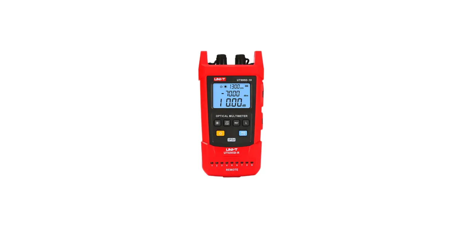
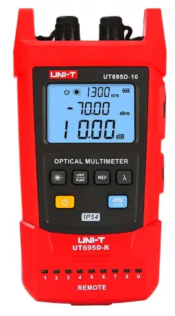
UNI-T UT695D Series Optical Multimeters
Preface
Thank you for purchasing the new UT695D series optical multimeters. In order to use these products safely and correctly, please read this manual thoroughly, especially the Safety Warning part.
After reading this manual, it is recommended to keep the manual at an easily accessible place, preferably close to the device, for future reference.
Limited Warranty and Liability
Uni-Trend guarantees that the product is free from any defect in material and workmanship within one year from the purchase date. This warranty does not apply to damages caused by accident, negligence, misuse, modification, contamination or improper handling. The dealer shall not be entitled to give any other warranty on behalf of Uni-Trend. If you need warranty service within the warranty period, please contact your seller directly.
Uni-Trend will not be responsible for any special, indirect, incidental or subsequent damage or loss caused by using this device.
Safety Warning
This manual contains the necessary operating instructions and equipment maintenance method. Please read each part of it carefully before using the equipment.
If the manual is not read or the operating instructions are not understood, the operation may cause inaccurate test results or damage the equipment, or even endanger personal safety.
This version of the manual is subject to change without prior notice.
Symbol Description
- Warning or Caution
- Complies with European Union standards
- Do not discard the battery as unsorted municipal waste. Please
- place it in a fixed battery recycling station for disposal.
- Please read the instructions before use
Introduction
UT695D series handheld mini optical multimeters integrate three functions of optical signal power measurement, optical fiber continuity detection and LAN cable sequence test. The products are beautiful and durable with ergonomic design. They have various functions, including IP54 dust and water prevention, flashlight, backlight display , automatic identification of light modulation frequency, auto power off, wavelength memory, user calibration, and ultra-wide optical power test range. The products are widely used in optical cable construction and maintenance, optical fiber communication, optical fiber sensing, optical CATV and other fields.
Models
| Model | UT695D-05 | UT695D-10 |
| Name | OPTICAL MULTIMETER | OPTICAL MULTIMETER |
| Main function | Power meter + 5mW visual fault locator + LAN cable sequence test | Power meter + 10mW visual fault locator + LAN cable sequence test |
| Power of visual fault locator | >5mW | >10mW |
Features
- Simultaneous display of linear mW and nonlinear dBm
- IP54 dust and water prevention
- Visual fault locator function
- LAN cable sequence test
- Auto power off
- Powered by lithium battery
- Low battery indication
- Flashlight function
- User self-calibration function
- Wavelength memory function
- FC, SC and ST port
- Battery life ≥60 hours
- Conforms to EN61326-1:2013 and EN61326-2-2:2013 standards
Structure
Structure Diagram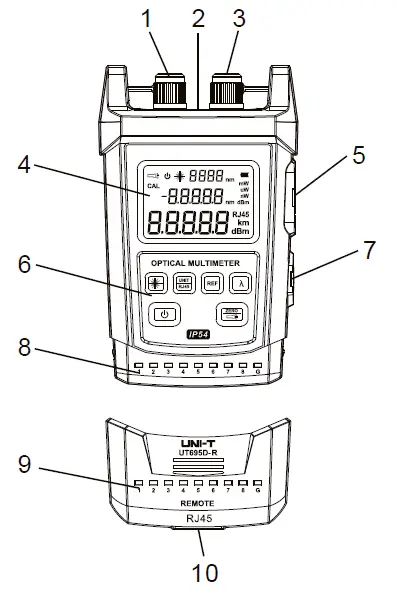
| 1 | Visual fault locator interface |
| 2 | Flashlight |
| 3 | Optical power interface |
| 4 | LCD |
| 5 | RJ45 interface of the master device |
| 6 | Keypad |
| 7 | Mini USB charging port |
| 8 | Line sequence indicators of the master device |
| 9 | Line sequence indicators of the slave device |
| 10 | RJ 45 interface of the slave device |
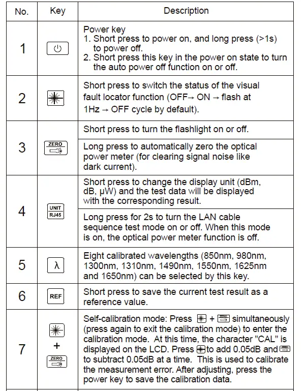
Key Description

Specifications
|
Optical power meter | Wavelength range | 800nm~1700nm |
| Measurement range | -70dBm~+3dBm | |
| Uncertainty | ±5% | |
| Display resolution | Linear: 0.1%, logarithmic: 0.01dBm | |
| Connector | Universal connector FC/SC/ST | |
| Detector type | InGaAs | |
|
Visual fault locator | Wavelength | 650nm±10nm |
|
Power | UT695D-10: 10mW (measurable optical fiber length: 8~10km) | |
| UT695D-05: 5mW (measurable optical fiber length: 2~5km) | ||
| Connector | Universal connector FC/SC/ST | |
| LAN cable sequence test | Line sequence measurement | |
| Flashlight | Flashlight function | |
| Power supply | 1050mAh polymer lithium battery | |
| Low battery indication | Low battery indication at 3.3V, auto power off at 3V | |
| Working current | <30mA when the visual fault locator function is off | |
| <130mA when the visual fault locator function is on | ||
| Dimensions | 136mm×71mm×41mm | |
| Weight | 175g | |
|
Operating environment | Operating temperature: 0°C~40°C | |
| Storage temperature: -10°C~50°C | ||
| Operating humidity: 20~75% RH(N.C) | ||
| Storage humidity: 10~90% RH(N.C) | ||
| Altitude: ≤2000mȄ | ||
| IP rating | IP54 (Host only) | |
| Certification | CE (EMC EN61326-1:2013, EN61326-2-2:2013) | |
Remarks:
- Wavelength range: the calibrated operating wavelength range from 800nm to 1700nm, in which the optical power meter can work under specified index.
- Measurement range: the range in which the maximum power can be measured according to the specified index.
- Uncertainty: the error between the measurement results of a given optical power and a standard optical power.
- The measurable optical fiber length is for reference.
Operating Instructions
Measurement of Absolute and Relative Power
Absolute Power Measurement
Set the test wavelength and access the test optical signal. Then the screen will display the measured linear value (in mw, nw, uw) and nonlinear value (in dBm) of the absolute optical power.
Relative Power (Loss) Measurement
Relative power measurement is mainly used to measure insertion loss or fiber link loss.
- Use a standard test jumper to connect the output port of a light source to the optical power interface of the optical multimeter.
- Set the test wavelength and access the test optical signal. Then the screen will display the measured linear value (in mw, nw, uw) and nonlinear value (in dBm) of the absolute optical power.
- Press and the measured absolute optical power will be saved as the reference power value and displayed as xx.xx dBm on the second line of the screen.
- Connect the optical fiber under test to the light source and the optical multimeter. The difference between the current optical power value and the reference power value will be calculated and displayed as y.yy dB on the third line of the screen, which is approximately the insertion loss of the optical fiber under test.
Note:
- P (Reference power value) (dBm) = p (Light source output power) (dBm) – L (Insertion loss of the standard test jumper) (dB)
- L (Insertion loss of the optical fiber under test) (dB) = [P (reference power value) (dBm) – p (current power value) (dBm)] – L (Insertion loss of the standard test jumper) (dB)
The optical multimeter can automatically identify the frequency of 0Hz, 270Hz, 1000Hz and 2000Hz emitted by the light source.
Visual Fault Locator Function Test
- Open the left dust cap and insert the optical fiber under test into the visual fault locator interface.
- Press in the power on state, and select the continuous red light or pulse mode to test.
- After the test, pull out the optical fiber, cover the dust cap, and then turn off the optical multimeter
LAN Cable Sequence Test
- Remove the slave device from the buckle of the master device.
- Connect one end of the LAN cable under test to the RJ45 interface of the master device and the other end to that of the slave device.
- Power on the optical multimeter, long press for 2s to turn the LAN cable sequence test mode on and “RJ45” will be displayed on the LCD.
If the corresponding line sequence indicators (1~G) on the master and slave devices are lit in turn, the line sequence of the measured LAN cable is correct. Otherwise, the line sequence is incorrect. The status (open circuit, short circuit, cross circuit, etc.) of the LAN cable can be judged by the line sequence indicators
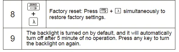
Self-calibration and Factory Reset
Please refer to 3.2 Key Description (7 and 8).
Standard Configuration
| No. | Article | Qty |
| 1 | Optical multimeter | 1 pc |
| 2 | User manual | 1 pc |
| 3 | USB charging cable | 1 pc |
Common Troubleshooting
| Symptom | Cause | Solution |
| LCD displays weakly | Low battery | Replace the battery |
| No display on booting | Low battery or other causes | Reboot or replace the battery |
| LCD displays abnormal data | The connector is faulty, dirty or locked | Reconnect the connector and clean the sensor |
| Output power of the red light is insufficient | The connector is faulty or dirty | Reconnect the connector and clean the laser head |
Daily Maintenance
- Please keep the end face of the sensor clean, free from grease and contamination. Do not use unclean or non-standard adapter connectors.
- Do not insert the end face with poor polishing.
- Please stick to a kind of adapter as far as possible.
- Once the equipment is not in use, please cover the dust caps immediately.
- Please insert and remove the optical adapter connector carefully to avoid scratches on the port.
- Please wipe the sensor surface gently and regularly with a special cleaning swab in the circumferential direction.
uNI-TREND TECHNOLOGY (CHINA) CO., LTDP.
No.6, Gong Ye Bei 1st Road, Songshan Lake National High-Tech Industrial Development Zone, Dongguan City, Guangdong Province, China


