SIRHC LABS Cortex EBC Complete Kit with Internal Display

WIRING
The 1988-1995 Mustang PCM is inside the vehicle, behind the kick panel in the passenger side foot well near the door. The PCM has a single large 60-pin connector. Power, ground, RPM, vehicle speed, and throttle position signals can be accessed at the PCM connector.
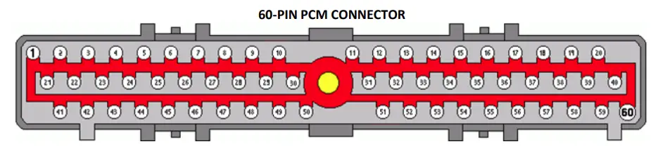
The Cortex EBC wiring harness and Speed Sensor Adapter V2 can be connected to the 60-pin PCM connector as outlined in the following tables. RPM and vehicle speed signals are required for boost by gear applications. The Speed Sensor Adapter V2 can be connected to the same power and ground source as the Cortex EBC if desired
CORTEX EBC TO PCM CONNECTIONS
| CORTEX SIGNAL | CORTEX WIRE COLOR | PCM SIGNAL | PCM PIN | PCM WIRE COLOR |
| +12V Power | Red | Switched PCM Power | 37 | Red |
| Ground | Black (x2) | Connect to Chassis Near EBC | N/A | N/A |
| Engine Speed | Pink | Cam Position Signal (PIP) | 56 | Dark Blue Or Gray / Orange |
| General-Purpose | Orange | Throttle Position | 47 | Dark Green/Light Green Or Gray/White |
SPEED SENSOR ADAPTER V2 CONNECTIONS
| SPEED SENSOR ADAPTER V2 SIGNAL | SPEED SENSOR ADAPTER V2 WIRE COLOR | PCM SIGNAL | PCM PIN | PCM WIRE COLOR |
| Sensor IN+ | Green | VSS + | 3 | Dark Green / White Or Gray / Black |
| Sensor IN- | Blue | VSS – | 6 | Orange / Yellow Or Pink / Orange |
| – | – | CORTEX SIGNAL | – | CORTEX WIRE COLOR |
| Output | White | Vehicle Speed | – | Green |
VEHICLE CONFIGURATION SETTINGS
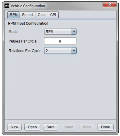
RPM DETECTION:
- Pulses Per Cycle: 8
- Rotations Per Cycle: 2
GEAR DETECTION:
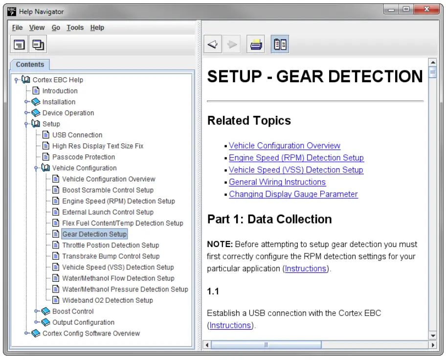
- Follow the steps in the Setup – Gear Detection section of the Help utility to determine the correct EVS ratio settings for gear detection.

SPEED DETECTION:
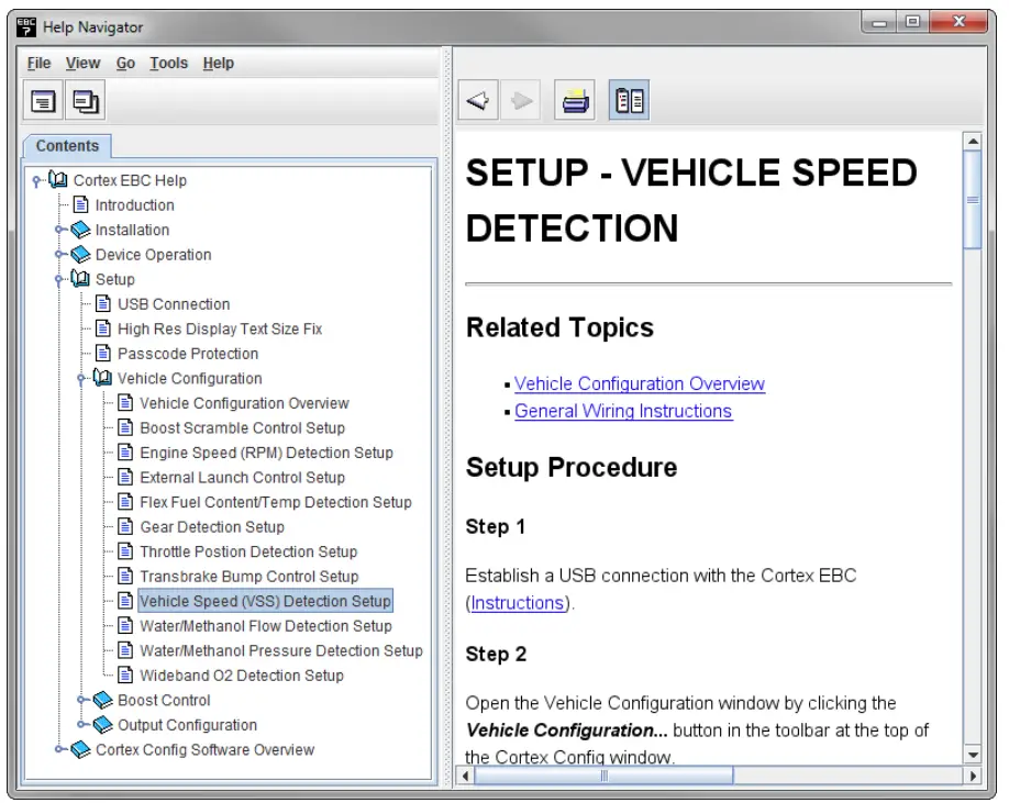
- Follow the steps in the Setup – Vehicle Speed Detection section of the Help utility to determine the correct Pulses Per Mile setting.
- NOTE: Gear detection setup should be performed before calibrating the Pulses Per Mile setting.

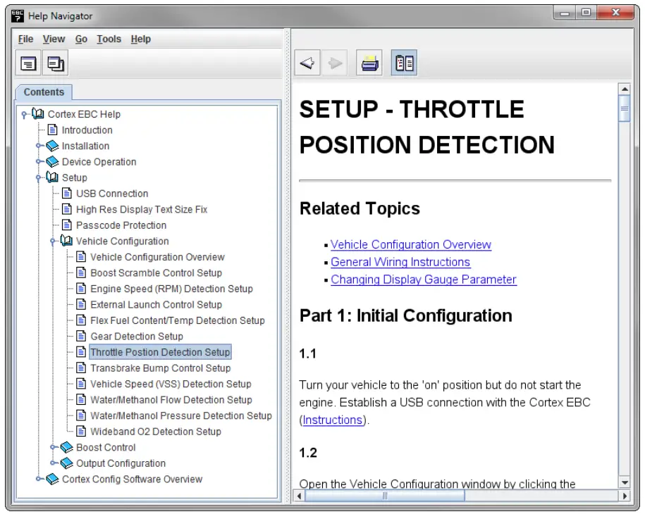
THROTTLE POSITION DETECTION:
- Follow the steps in the Setup – Throttle Position Detection section of the Help utility to determine the correct Closed TPS Voltage and Open TPS Voltage settings.