SIRHC LABS CORTEX EBC Affordable Gear Based Boost Control
WIRING
The 2011-2014 F-150 PCM is in the passenger side of the engine bay on the firewall. The PCM has three connectors. Power, RPM, vehicle speed, and throttle position signals can be accessed at these connectors. When the PCM is installed in the vehicle the Transmission connector will be on the right, the Engine connector will be in the middle, and the Cowl connector will be on the left.
Overview
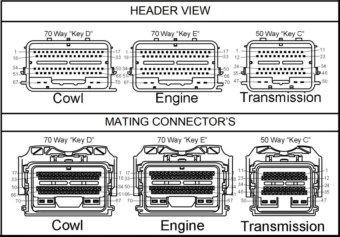
The Cortex EBC wiring harness can be connected to the PCM connectors as outlined in the following table (C = Cowl Connector, E= Engine Connector, T = Transmission Connector). RPM and vehicle speed signals are required for boost-by-gear applications.
CORTEX EBC TO PCM CONNECTIONS
| CORTEX SIGNAL | CORTEX WIRE COLOR | PCM SIGNAL | PCM PIN | PCM WIRE COLOR |
| +12V Power | Red | Switched PCM Power | C-67 | Green / Blue |
| Ground | Black (x2) | Connect to Chassis Near EBC | N/A | N/A |
| Engine Speed | Pink | Intake Cam Position Sensor (CMP21) | E-42 | Yellow / Blue |
| Vehicle Speed | Green | Output Shaft Speed | T-14 | Brown / Green |
| General-Purpose | Orange | Throttle Position 1 | E-39 | Brown |
VEHICLE CONFIGURATION SETTINGS
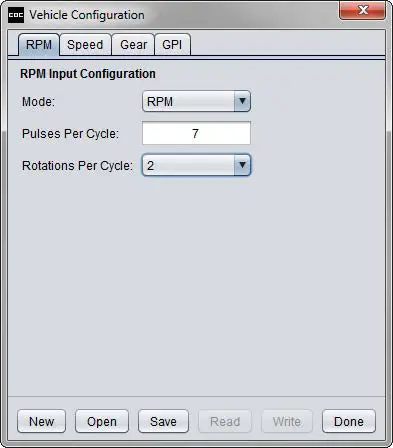
RPM DETECTION
- Mode: RPM
- Pulses Per Cycle: 7
- Rotations Per Cycle: 2

GEAR DETECTION
Follow the steps in the Setup – Gear Detection section of the Help utility to determine the correct EVS ratio settings for gear detection.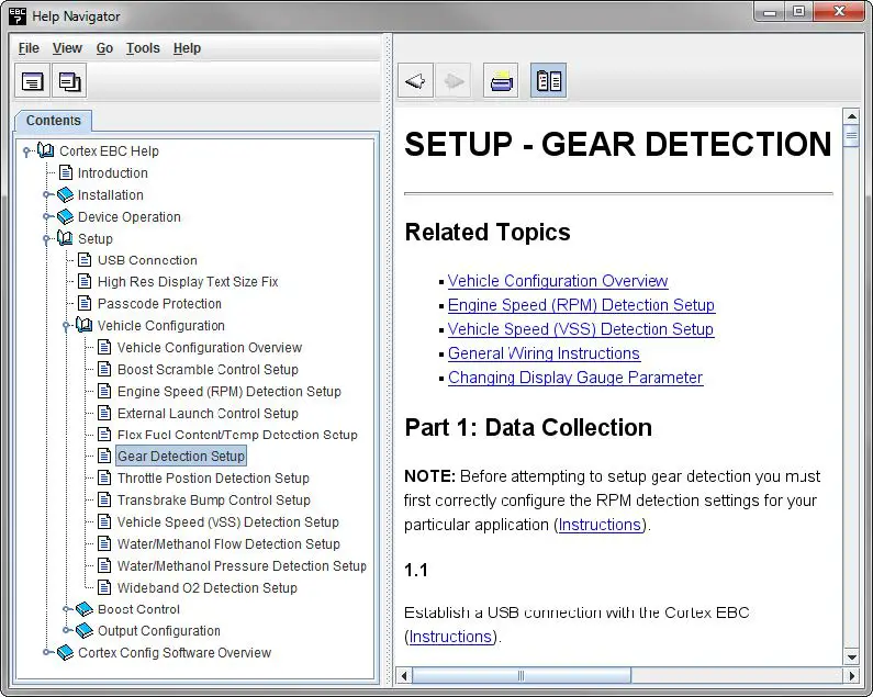
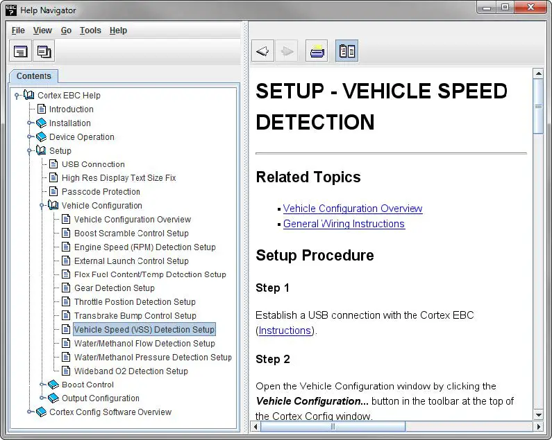
SPEED DETECTION
- Follow the steps in the Setup – Vehicle Speed Detection section of the Help utility to determine the correct Pulses Per Mile setting.
- NOTE: Gear detection setup should be performed before calibrating the Pulses Per Mile setting.

THROTTLE POSITION DETECTION
Follow the steps in the Setup – Throttle Position Detection section of the Help utility to determine the correct Closed TPS Voltage and Open TPS Voltage settings.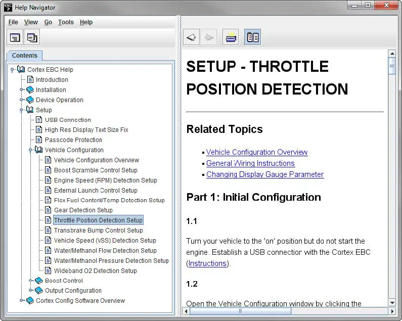
SIRHC Labs 2022.


