![]() www.jbctools.com
www.jbctools.com
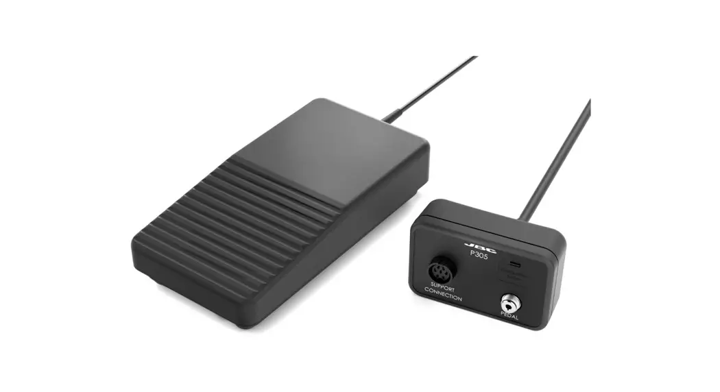
INSTRUCTION MANUAL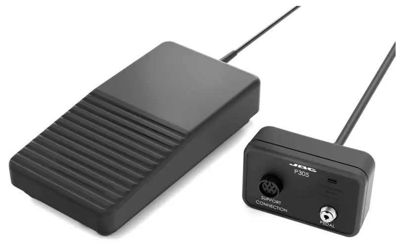 P305
P305
Pedal Kit for Control Units
This manual corresponds to the following references:
P-305
Packing List
The following items are included:
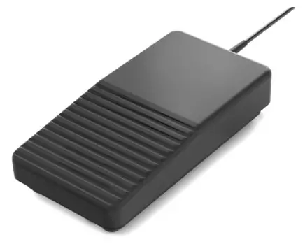 |  |  |
| Pedal …………………………………………………….1 unit | Adapter …………………………………………………1 unit | Manual ……………………………………………. 1 unit Ref. 0028918 |
Connection Example
Connect the tool stand and the pedal to the adapter. Then connect the adapter to the station port.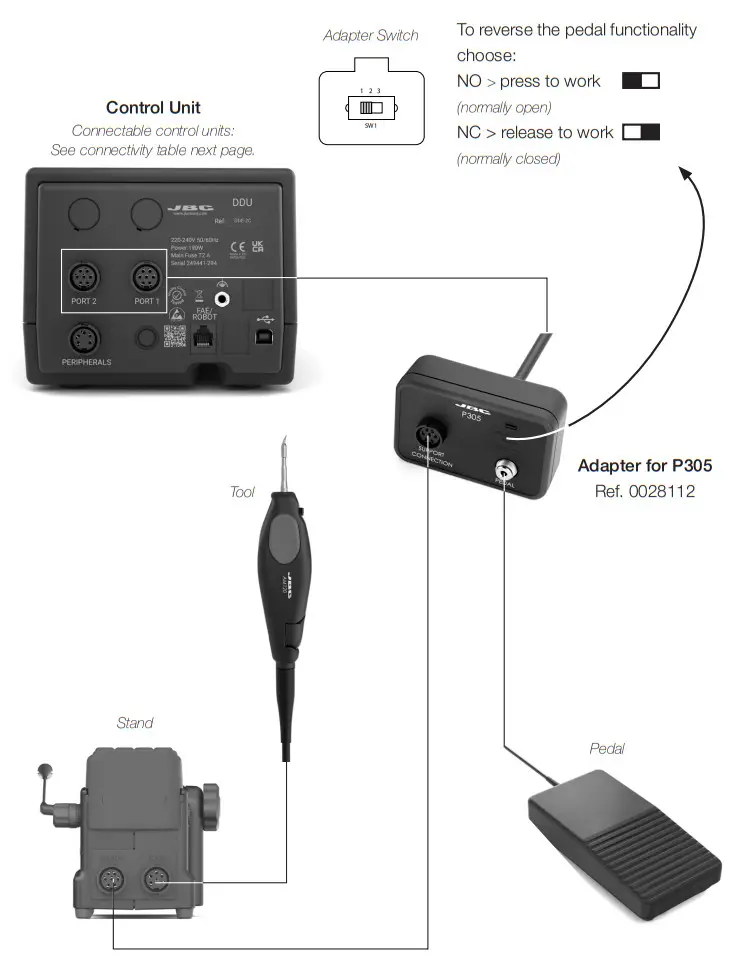
Pedal Compatibility
P305 is compatible with JBC devices as shown in the table in the highlighted column.
P405* and P005* is also shown in the table below.
Marked with means pedal P405/P005 cannot be connected directly to JBCs control unit. A module (MSE, MVE, MNE) must be used (See next page “Pedal Set Up”).
| Pedals | ||||
| P405* | P305 | P005* | ||
| DIU | ||||
| DDU | ||||
| DMU | ||||
| Control Unit | HDU | |||
| JANU | ||||
| JTA | ||||
| WSU | ||||
| ALU | ||||
| NAU | ||||
| Station | AL | |||
| Module | MSE | |||
| MOVE | ||||
| MNE | ||||
| Preheater | PINK | |||
| PHIL | ||||
| PHBK | ||||
| PHXK | ||||
| Fume Extractor | FAE1 | |||
| FAE2 | ||||
 Pedal Set Up for
130 mm
– DIU (Control Unit)
– WSU (Wire Stipper Station)
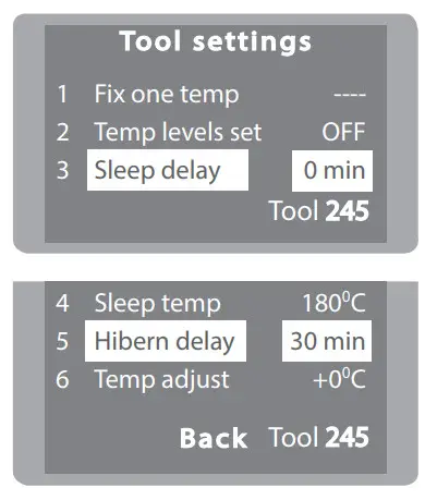
In order for the tool not to heat up the component before the pedal is pressed, the station’s Sleep
Delay and Hibernation Delay function must be set to 0 min.
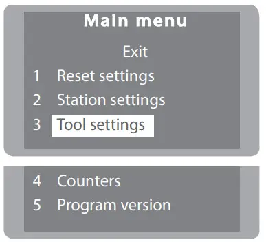
Pedal Set Up P305
- Enter the Main Menu and select Tool Settings

- Change Sleep Delay and Hibernation Delay to 0 min.

Pedal Set Up for:
– DDU, HDU (Control Units)
Note: Peripheral module – MSE, MVE or MNE – are needed to connect the pedal to DDU y HDU.
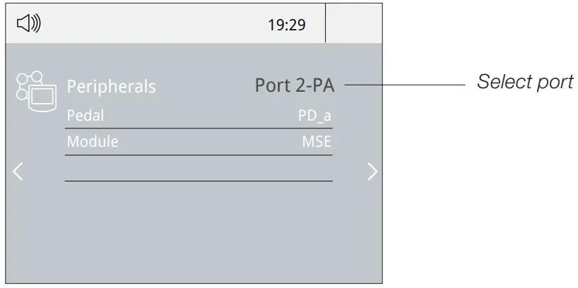
- Enter the Peripherals Menu and select the port which you want to join to the pedal.

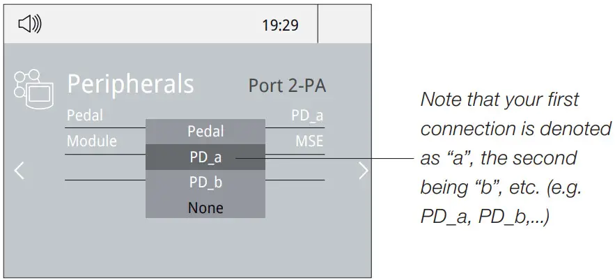
- Select the pedal from the list.

- Set the pedal function according to your work needs:

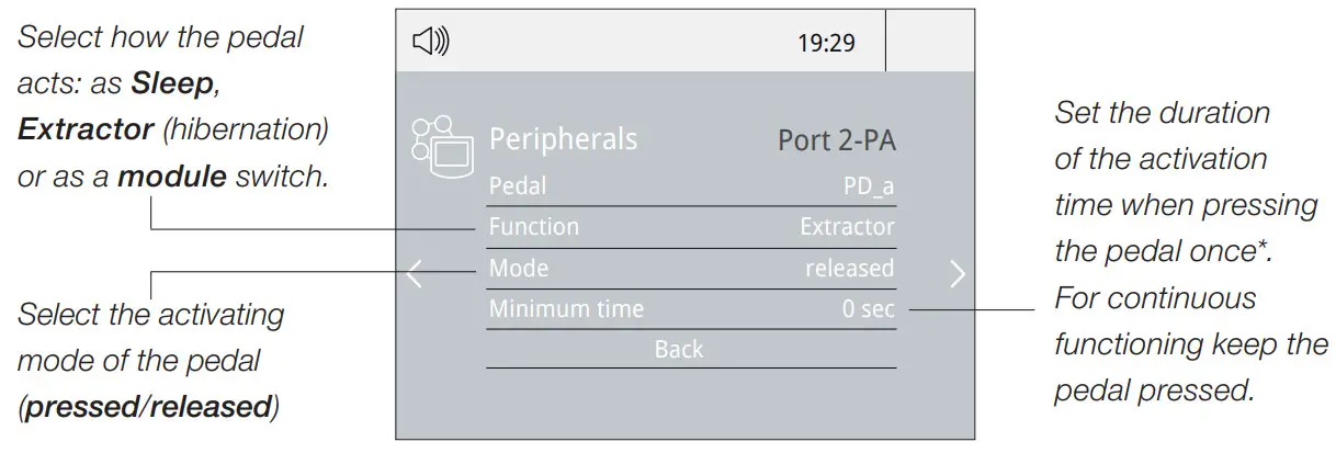
*NB: The same can be applied inversely by continually pressing the pedal and releasing to activate.
Pedal Set Up for DMU (Control Unit)
Note: Peripheral moduls – MSE, MVE or MNE – are needed to connect the pedal to DMU.
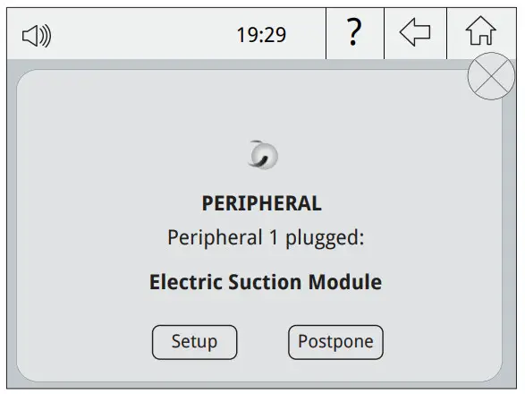
After connecting one of the mentioned moduls to the station a popup window opens.
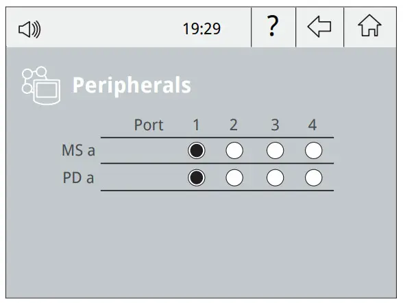
- To configure the module MSE/MVE/MNE press Setup in the popup window.

- Select the module from the list of peripheral connections. Remember your first connection is denoted as “a”, the second being “b”, etc. (e.g. MS_a, MS_b,…). Do the same with the pedal (e.g.PD_a,…)
- Select the port of the tool you want to link to the peripheral.

- Press Menu or Back to save changes.
Once set up, the module settings can be changed by entering the Peripherals Menu.
Example:
Chip Components Rework Process using Tweezers and Pedal
The Pedal is frequently used to rework components with tweezers.
AN115 JBCs adjustable nano tweezers is the most effective tool for desoldering chip components but also it facilitates its rapid placement and soldering by using P405 pedal connected to JBC´s NAS station.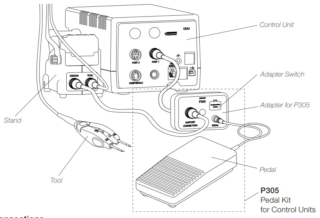
Connections
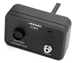
Connect pedal P305 to its adapter and then the adapter to the control unit port. The tool must be connected to its sand and the stand to the pedal adapter.
In the peripherals menu for the “Pedal Activation Mode” choose between “pressed” and “released”.
Note: If working with P305 and its adapter, choose the pedal functionality at the adapter switch like shown beside.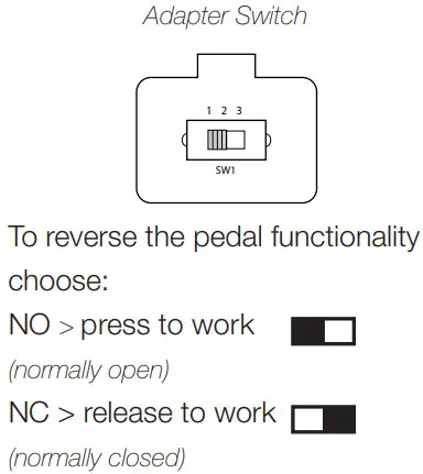
* “Press Mode” previously selected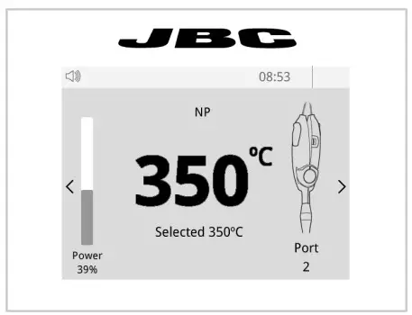
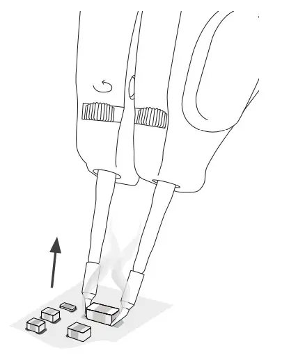
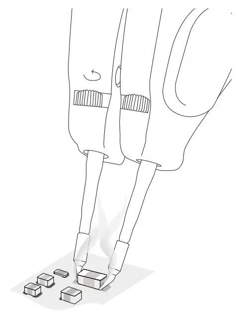
Desoldering*
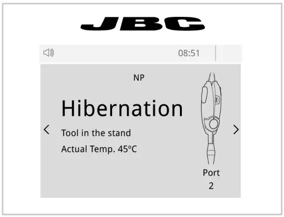
Lift the tool from the holder, press and hold the pedal to activate the tool and desolder the component.
Once the pedal is released the tool enters in hibernation mode and cools down.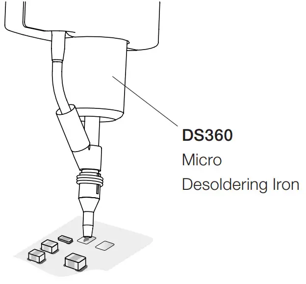
Pad Cleaning
Clean the pads with JBC´s desoldering tool DS360.
For this operation JBC´s desoldering station DSS is needed.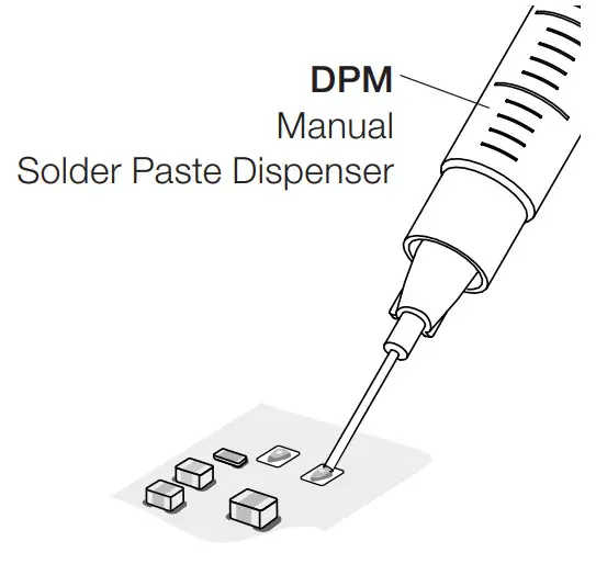
Solder Paste Dispensing
Apply the solder paste amount needed to solder the new chip component.
The use of JBC´s DPM solder paste dispenser is recommended.
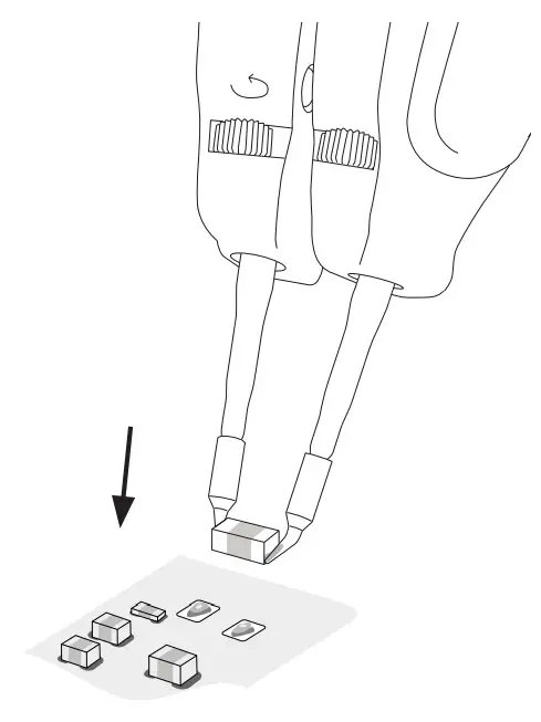 |  |
Placing
Do not press the pedal.
Use the tool to position the component on the previously tinned pad.
Note: The inactive tool prevents the component from heating up prematurely.
 | 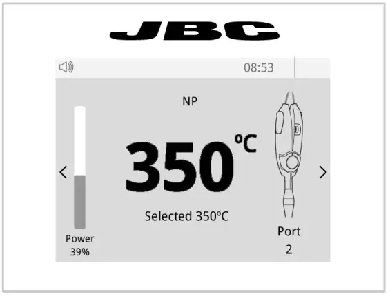 |
Soldering
Once in position press and hold the pedal to activate the tool and perform the soldering.
Notes
Specifications
P305
Pedal Kit for Control Units
Ref. P-305
| – Pedal Cable Length: | 1.9 m / 74.80 in |
| – Total Net Weight: | 513 g / 1.13 lb |
| – Total Package Dimension / Weigt: | 342 x 155 x 120 mm / 783 g |
| (L x W x H) | 13.46 x 6.10 x 4.72 in / 1.73 lb |
Complies with CE standards ESD safe
![]()
Warranty
JBC’s 2-year warranty covers this equipment against all manufacturing defects, including the replacement of defective parts and labor.
The warranty does not cover product wear or misuse.
In order for the warranty to be valid, equipment must be returned, postage paid, to the dealer where it was purchased.
![]() This product should not be thrown in the garbage.
This product should not be thrown in the garbage.
In accordance with the European directive 2012/19/EU, electronic equipment at the end of its life must be collected and returned to an authorized recycling facility.
![]() 0028918-0522
0028918-0522
www.jbctools.com


