TRINAMIC TMC2225-BOB Breakout Board Installation Guide

TMC2225-BOB
Document Revision V1.02 • 2021-Mar-01
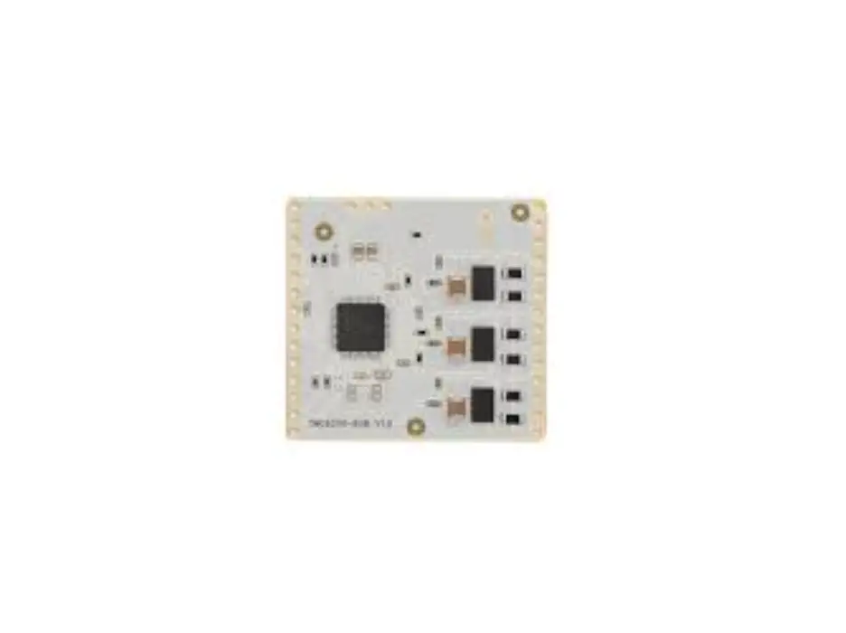
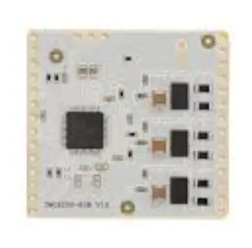
Module Top View
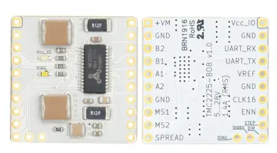
Pin List
| Left | Signal | Right | Signal |
| 1 | VCC_IO | 11 | +VM |
| 2 | GND | 12 | GND |
| 3 | UART_RX | 13 | B2 (Motor Phase B) |
| 4 | UART_TX | 14 | B1 (Motor Phase B) |
| 5 | VREF | 15 | A1 (Motor Phase A) |
| 6 | GND | 16 | A2 (Motor Phase A) |
| 7 | CLK16 | 17 | GND |
| 8 | ENN | 18 | MS1 |
| 9 | STEP | 19 | MS2 |
| 10 | DIR | 20 | SPREAD |
| 21 | INDEX | 22 | DIAG |
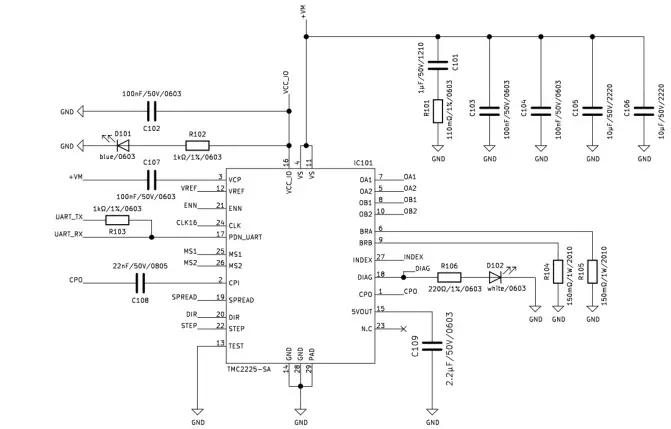
Schematics
Features and additional Resources
- TMC2225-SA stepper motor driver
- Supply voltage 5-28V
- Iphase up to 4ARMS
- Quiet operation with StealthChop™
- Configuration and extended diagnostics via UART
- Control via Step&Dir interface
- Board width 0″, board height 1.0″
- 2×10 pin 1″ header rows for pins/connectors
- Link to additional information and IC data sheet
Bill of Materials
| Pcs. | Value | Footprint | Description |
| 1 | blue/0603 | 0603 | LED |
| 1 | white/0603 | 0603 | LED |
| 1 | R0603/0R11/1% | 0603 | Resistor |
| 2 | R0603/1k/1% | 0603 | Resistor |
| 1 | R0603/220R/1% | 0603 | Resistor |
| 1 | 2u2/50V | 0603 | Capacitor |
| 1 | 22n/50V | 0603 | Capacitor |
| 1 | 1uF, 50V | 1210 | Capacitor |
| 2 | 10uF, 50V | 2020 | Capacitor |
| 4 | 100nF, 50V | 0603 | Capacitor |
| 2 | R2010/0R15 | 2010 | Resistor |
| 1 | TMC2225-SA | HTSSOP28 | Trinamic Stepper Motor Driver |
©2021 TRINAMIC Motion Control GmbH & Co. KG, Hamburg, Germany Terms of delivery and rights to technical change reserved
Download newest version at www.trinamic.com


