FORENEX FR-DTE R232 Breakout Board
Product Information
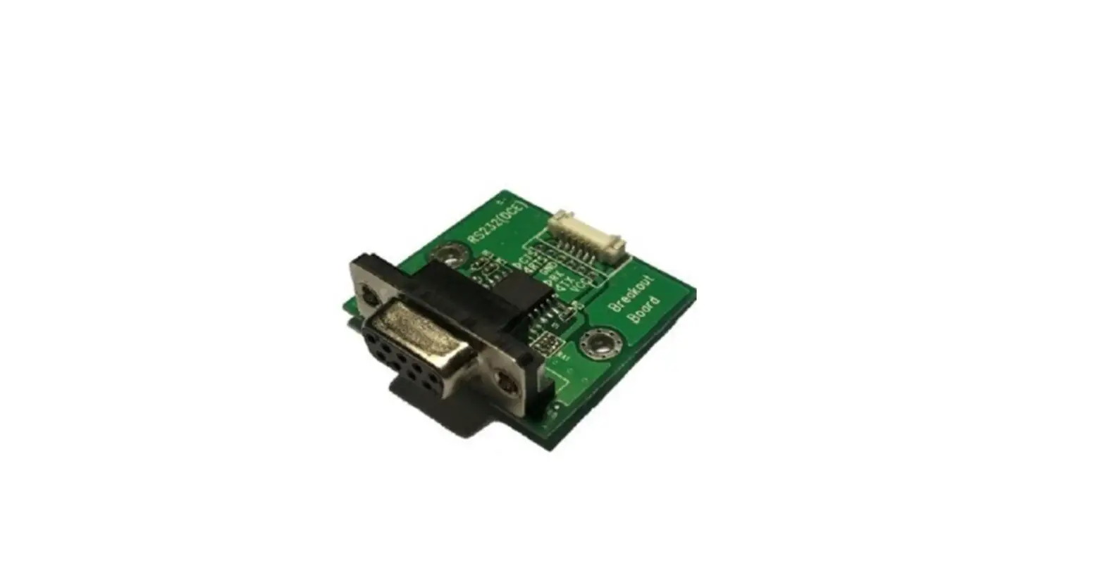
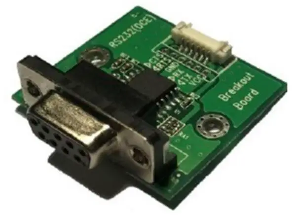
The FR-DTE (RS232) Breakout Board is a device that converts UART-TTL logical level to RS232. It features a UART-TTL with 3.3V/5V tolerance input and RS232 that provides 3-wire or 5-wire mode. The device is RoHS compliant and comes in two ordering options: FR-DTE-W (with wire-to-board connector) and FR-DTE-D (with board-to-board header). The device also comes with a 6-pin to 6-pin wire cable for input, L=150mm (WC7067060153).
Product Usage Instructions
- Connect the power input (3.3V/5V) to Pin 1 (P) of the UART-TTL connector.
- Connect the UART-TX (transmit) of your device to Pin 2 (I) of the UART-TTL connector.
- Connect the UART-RX (receive) of your device to Pin 3 (O) of the UART-TTL connector.
- Connect the ground (GND) of your device to Pin 4 (P) of the UART-TTL connector.
- If you are using the 5-wire mode, connect the UART-RTS (ready to send) of your device to Pin 5 (I) of the UART-TTL connector, and connect the UART-CTS (clear to send) of your device to Pin 6 (O) of the UART-TTL connector.
- If you are using the 3-wire mode, connect Pin 5 (I) and Pin 6 (O) of the UART-TTL connector to NC (no connection).
- If you are using FR-DTE-W, connect the DTE-RXi (receive input) of your device to Pin 2 (I) of the board-to-board connector, and connect the DTE-RTSo (ready to send output) of your device to Pin 7 (O) of the board-to-board connector. Connect the DTE-TXo (transmit output) of your device to Pin 3 (O) of the board-to-board connector, and connect the DTE-CTSi (clear to send input) of your device to Pin 8 (I) of the board-to-board connector.
- If you are using FR-DTE-D, connect the pins according to your board-to-board header.
General Description
Making UART-TTL logical level convert to RS232
Feature
UART-TTL with 3.3V/ 5V tolerance input. RS232 provide 3-wire or 5-wire mode. RoHS Compliant.
Ordering Information
- FR-DTE-W: with wire to board connector.
- FR-DTE-D: with board to board Header.
- WC7067060153: 6-pin to 6-pin, wire cable for input, L=150mm.
Connector
| UART-TTL Connector | |||||
| UART2: (Wafer_6pin,1.25mm, 90°) FR-DTE-W only | JP2: (Header-6pin, 2.0mm, 180°) FR-DTE-D only | ||||
| Pin num | Description | I/O | Pin num | Description | I/O |
| Pin1 | Power Input (3.3V/ 5V) | P | Pin1 | Power Input (3.3V/ 5V) | P |
| Pin2 | UART-TX | I | Pin2 | UART-TX | I |
| Pin3 | UART-RX | O | Pin3 | UART-RX | O |
| Pin4 | GND | P | Pin4 | GND | P |
| Pin5 | UART-RTS | I | Pin5 | UART-RTS | I |
| Pin6 | UART-CTS | O | Pin6 | UART-CTS | O |
| RS232 DTE Connector: (DB9, Male, 90°) | |||||
| Pin num | Description | I/O | Pin num | Description | I/O |
| Pin1 | NC | Pin6 | NC | ||
| Pin2 | DTE-RXi | I | Pin7 | DTE-RTSo | O |
| Pin3 | DTE-TXo | O | Pin8 | DTE-CTSi | I |
| Pin4 | NC | Pin9 | NC | ||
| Pin5 | GND | ||||
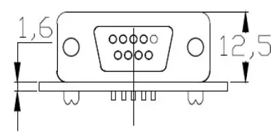
Dimension
FR-DCE-W 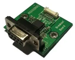
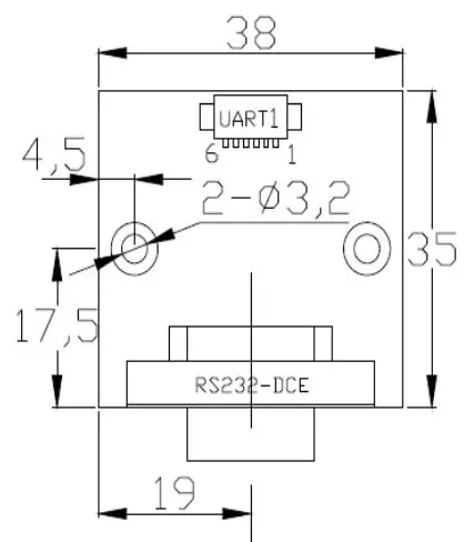
FR-DCE-D 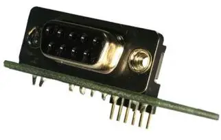
- TEL: 886-4-22969886
- FAX: 886-4-22969887


