![]()
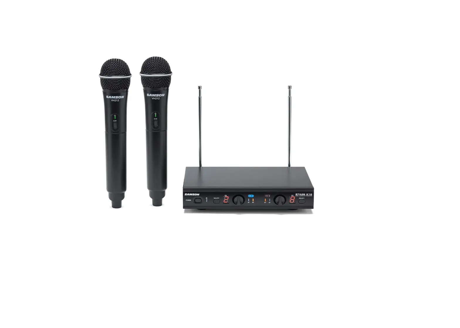
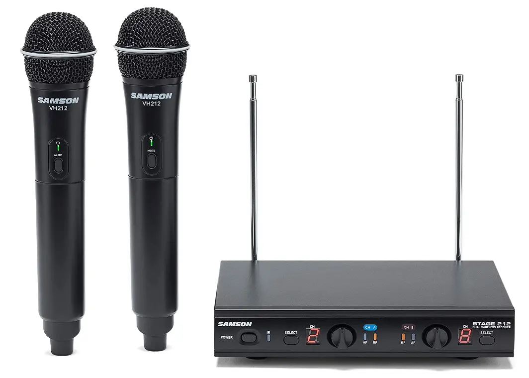
Samson SWS212HH-E Stage 212 Handheld Dual-Channel Wireless System
INTRODUCTION
Two handheld dynamic microphones that transmit to a single tough metal receiver are provided by the dual-channel, frequency-adaptive Samson stage 212 wireless microphone system. Each handheld has a Samson Q6 dynamic mic element, which offers clean, crisp sound and dependable VHF wireless performance for dual-performer applications such as home karaoke, live presentations, education, houses of worship, and others. Samson has committed itself to foster wireless innovation and working tirelessly to make cord-cutting easier for performers worldwide. 12 working channels are available for selection across a frequency range of 179 MHz to 197 MHz thanks to the frequency-agile design of stage 212. Additionally, users can quickly wirelessly synchronize each transmitter to a receiver operating frequency thanks to the system’s IR sync function.
FEATURES
- Professional, dual-handheld wireless system for use in both live sound and sound contracting applications
- 12 available channels operating in the VHF band designed for maximum system compatibility in the same location without interference
- Individual ¼” and mixed XLR outputs
- Up to 200’ of line-of-sight operating range
- Two professional VH212 handheld transmitters with Q6 Dynamic Microphone capsules
- Up to 10 hours of battery life, using two standard AA batteries
SR212 RECEIVER FRONT PANEL FEATURES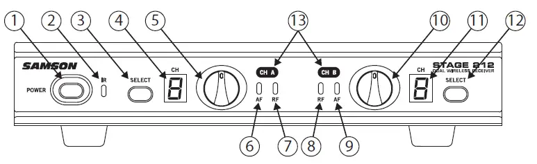
- Power Switch – Press to turn the receiver on or off.
- IR Transmitter – During “IR SET” an infrared light is used to set the transmitter channel.
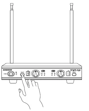
- Channel A SELECT Button – Press this button to cycle through Channel A receiver’s operating channels. Press and hold this button to send the channel information to the transmitter via infrared transmission.
- LED Display – The 7-segment LED display shows each receiver’s current operating channel. The channels are indicated by 1–9 and A–C.
- VOLUME Control (CH A) – This knob sets the level of the audio signal being output through the CH A output jacks on the rear panel. The reference level is obtained when the knob is turned fully clockwise (to its “10” setting).
- Channel An AF Indicator – Lights green when the corresponding Channel A VH212 transmitter is powered on, and there is an audio signal present and detected by the receiver. The indicator lights red when the transmitted audio signal is overloaded.
- Channel A RF Indicator – Lights orange when the corresponding Channel A VH212 transmitter is powered on, and there is an RF signal present and detected by the receiver.
- Channel B AF Indicator – Lights green when the corresponding Channel B VH212 transmitter is powered on, and there is an audio signal present and detected by the receiver. The indicator lights red when the transmitted audio signal is overloaded.
- Channel B RF Indicator – Lights orange when the corresponding Channel B VH212 transmitter is powered on, and there is an RF signal present and detected by the receiver.
- Volume Control (Channel B) – This knob sets the level of the audio signal being output through the CH A output jacks on the rear panel. The reference level is obtained when the knob is turned fully clockwise (to its “10” setting).
- LED Display – The 7-segment LED display shows each receiver’s current operating channel. The channels are indicated by 1–9 and A–C.
- Channel B SELECT Button – Press this button to cycle through Channel B receiver’s operating channels. Press and hold this button to send the channel information to the transmitter via infrared transmission.
- Channel Label – The channel label designates the frequency group. The label color matches the label color of the corresponding handheld microphone transmitter.
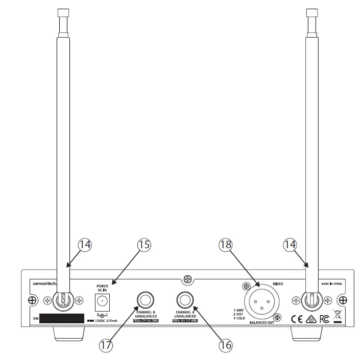
SR212 RECEIVER REAR PANEL FEATURES
- Antenna – The antenna mountings allow full rotation for optimum placement. In normal operation, both antennas should be placed in a vertical position. The antennas can be folded down for convenience when transporting the SR212.
- DC Input – Connect the supplied 15-volt adapter here.
WARNING: Do not substitute any other kind of power adapter. Doing so can cause damage to the SR212 and will void your warranty. - Channel An Output – Use this unbalanced, ¼” jack to connect the SR212 Channel A receiver to the line level input of a mixer, amplifier, or other audio equipment.
- Channel B Output – Use this unbalanced, ¼” jack to connect the SR212 Channel B receiver to the line level input of a mixer, amplifier, or other audio equipment.
- MIXED OUT – This balanced, low-impedance XLR jack carries a mix of both the Channel A and Channel B receivers.
VH212 TRANSMITTER CONTROLS AND FEATURES
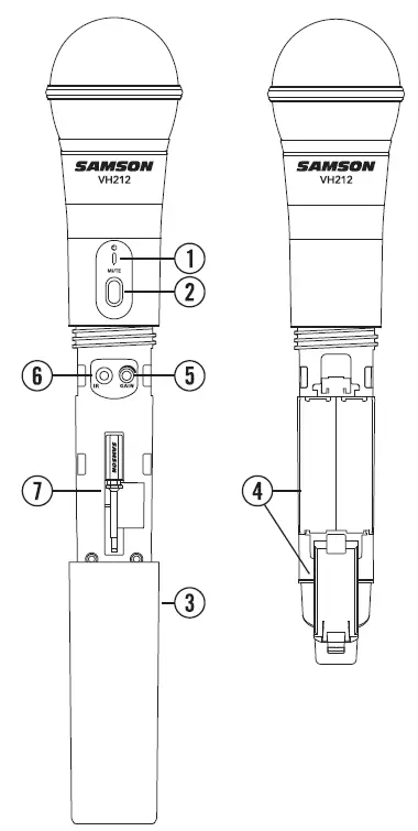
- Status Indicator – This LED displays the operation mode:
GREEN Normal Operation RED Mute Flashing GREEN Low Battery - Power/Mute Switch – Press and hold to turn the unit on or off. Press and release to mute or unmute the transmitter.
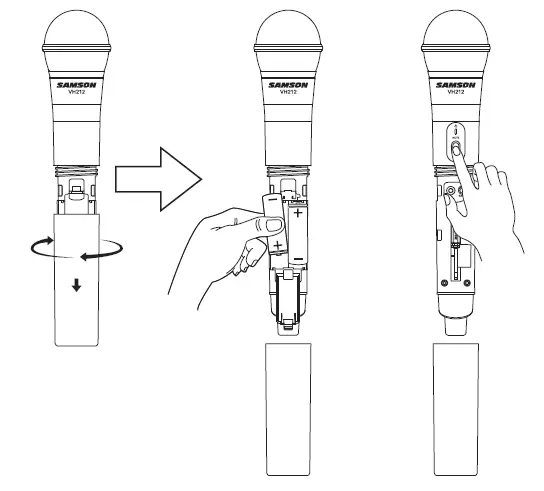
- Battery Cover – Unscrew the battery cover and slide down to open the VH212 battery compartment.
- Battery Holder – Open the battery holder by pressing the tab and lifting the cover. Insert two standard AA (LR6) batteries here, being sure to observe the plus and minus polarity markings shown.
WARNING: Do not insert the batteries back- wards; doing so can cause severe damage to the VH212 and will void your warranty.Input GAIN Control – This control adjusts the transmitter input sensitivity. For optimal performance, using the included screwdriver, set the input GAIN control to where you see the VH212 PEAK indicator start to light under high levels, then turn down until the PEAK light stops lighting. - IR Lens – This window is used to capture the infrared signal sent from the VH212 during the IR SET to channelize the transmitter. The battery cover must be open and the IR Lens facing towards the receiver to load the selected channel.
- Plastic Screwdriver – Designed for use in adjusting the VH212 input GAIN control (See #5 Input GAIN Control).
QUICK START
In order for your wireless system to work correctly, both the receiver and transmitter must be set to the same channel.
Follow this basic procedure for setting up and using your Stage 212 wireless system:
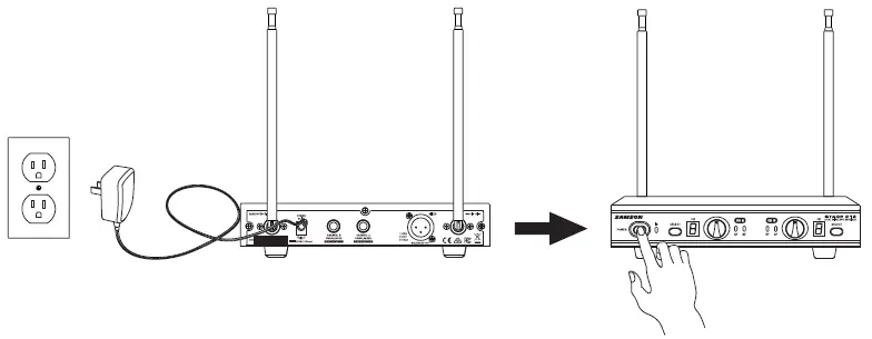
- Physically place the SR212 receiver where it will be used, and fully extend the antennas vertically. The general rule of thumb is to maintain “line of sight” between the receiver and transmitter so that the person using or wearing the transmitter can see the receiver.
- With the SR212 powered off, connect the included power adapter. Turn the SR212 on momentarily to confirm that the unit is receiving power. You’ll see the LED display light up. Then turn the SR212 power off.

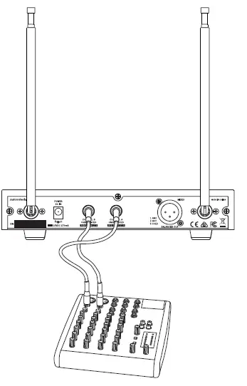
- With your amplifier or mixer off and volume control all the way down, connect the SR212 receiver 1/4” outputs (or XLR Mix Output) to the inputs of a mixer or amplifier. Turn the Level knob on the SR212 completely counterclockwise, then turn its power on.

- With the transmitter powered off, install two fresh AA batteries into VH212 handheld transmitter. Leave the battery compartment open.
- Turn on the power to the transmitter by pressing and holding Power switch; the indicator LED will light green.

- Press the CH A SELECT button on the front of the SR212 to choose an available channel for the CH A receiver. The channel number will increase by one digit, from 1–9 then A–C. Once the last channel has been reached, the count will cycle back to 1.

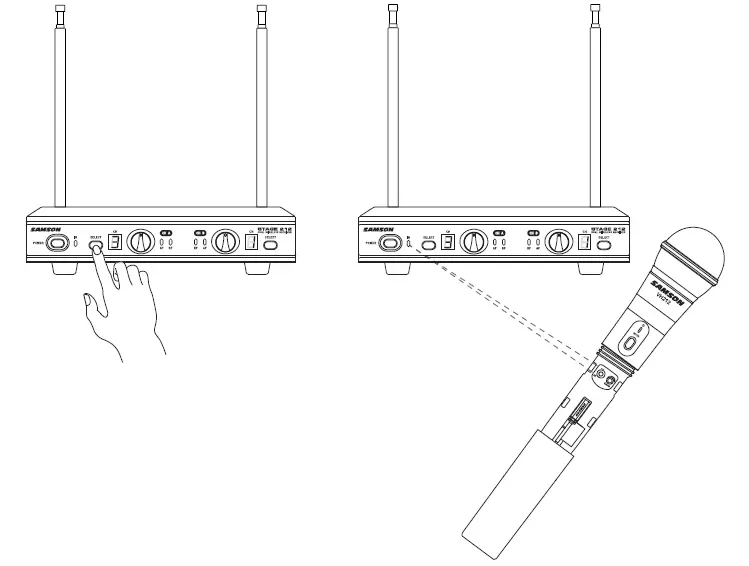
- Position the VH212 transmitter about 6-12″ (15-30 cm) from the front of the SR212 receiver with the transmitter’s IR window facing the IR transmitter on the front panel of the SR212 receiver.
- Press and hold the SR212 CH A SELECT button to set the transmitter to the same channel as the receiver via infrared transmission

- When the transmission is complete, the SR212 will receive RF signal and the tone key from the transmitter. The CH A READY indicator will light on the front panel of the SR212 receiver. Repeat these steps for the CH B transmitter and receiver. CH A and CH B available frequency channels do not overlap, so you can set the two receivers to the same channel number or letter.
- Turn on your connected amplifier or mixer, but keep the volume all the way down. Set the Volume knob on the SR212 fully clockwise (to its “10” setting). This is unity gain.
- Speak or sing into the microphone. Slowly raise the volume of your amplifier or mixer until the desired level is reached.
- If you find the system has noticeable dropouts, reduced overall working range, or unexpected noise bursts, change the operating channel of the system using the steps above.
- When using multiple systems in the same frequency band, each system must be set to a different operating channel.
SPECIFICATIONS
SYSTEM SPECIFICATIONS
- OPERATING FREQUENCY: VHF 173MHz to 198MHz
- NUMBER OF CHANNELS: 12 channels
- FREQUENCY STABILITY: ±0.005%
- MODULATION MODE: FM
- MAXIMUM DEVIATION: ±30 kHz
- OPERATING RANGE: 50 meter
- OPERATING TEMPERATURE RANGE: 40° to 43°
- WORKING HUMIDITY: 65±20%RH
- FREQUENCY RESPONSE: 80 Hz to 15kHz
- TONE KEY FREQUENCY:00kHz
SR212 RECEIVER SPECIFICATIONS:
- IMAGE REJECTION: 35 dB
- DYNAMIC RANGE: 100 dB
- MAXIMUM OUTPUT:37V
- SENSITIVITY: -100dBm@30dB SINAD
- OUTPUT CONNECTORS: Two 6.3mm unbalanced, One XLR balanced
- AUDIO OUTPUT LEVELS: -12dB
- POWER SUPPLY: 100-240V, 50/60Hz, 0.4A, Output: DC 15V, 800mA
- DIMENSIONS: 210 x 145 x 36 (mm)
- NET WEIGHT:6kg
VH212 TRANSMITTER SPECIFICATIONS
- RF POWER OUTPUT: 10mW
- MICROPHONE ELEMENT: Dynamic
- TYPICAL BATTERY LIFE: 10 hours
- CURRENT CONSUMPTION: 120 mA typical
- DIMENSIONS: Ö55 mm x 255 mm
- NET WEIGHT:22kg
TROUBLESHOOTING
| Issue | Solutions |
|
No Audio | Turn on the VH212 transmitter using the Power/Mute switch. |
| Ensure the VH212 transmitter’s batteries are installed correctly. | |
| Confirm that the SR212 adaptor is correctly connected and plugged into an electrical outlet. | |
| Turn on the SR212 receiver. | |
| Make sure the SR212 output and audio input connections are securely connected. | |
| Ensure that the SR212 receiver and VH212 transmitters are in line of sight with one another. | |
| Check the receiver and audio input device level controls. | |
|
Distorted Audio | Check the receiver output level and audio input device level. |
| Check the VH212’s batteries and replace if low. | |
| Another transmitter may be broadcasting on the same channel. Turn off transmitter that may be causing interference. | |
| Audio Dropout | The transmitter may be too far away from the receiver. Move closer to the receiver, or reposition the antennas. |
| Remove any sources that may cause RF interference, such as cell phones, cordless phones, lighting equipment, computers, etc. | |
| Transmitters and Receiver on Different Channels | Contact your Samson reseller or distributor for assistance. |
FAQs
Can two wireless mics be used simultaneously?
No. When setting up wireless microphone systems, a specific receiver is required for each microphone that will be used. To communicate with one another, the receiver and the microphone need to be on the same frequency.
Can many wireless mics be used simultaneously?
One active microphone transmitter at a time can only have its signal demodulated by a wireless receiver. However, as long as only one transmitter is turned on at any given time, you are free to utilize either on
What occurs if two microphones are using the same frequency?
Due to the receiver’s inability to discriminate between different signals, if two microphones are utilized simultaneously on the same frequency, they will interfere with one another.
Can two wireless mics be used simultaneously?
No. When setting up wireless microphone systems, a specific receiver is required for each microphone that will be used. To communicate with one another, the receiver and the microphone need to be on the same frequency.
Can many wireless mics be used simultaneously?
One active microphone transmitter at a time can only have its signal demodulated by a wireless receiver. However, as long as only one transmitter is turned on at any given time, you are free to utilize either one.
What occurs if two microphones are using the same frequency?
Due to the receiver’s inability to discriminate between different signals, if two microphones are utilized simultaneously on the same frequency, they will interfere with one another.
What is the range of a wireless microphone?
The typical range for systems of the kind detailed here (10-50 mW, VHF or UHF) can range from 100 feet to 1000 feet.
How much energy is consumed by a wireless microphone?
In contrast to wireless microphone systems, which typically have an output power of only 50 mW (fifty one thousandths of one watt! ), television transmitters can operate at power levels up to one million watts.
Can any receiver be used with a wireless microphone?
No, as wireless microphones may employ incompatible frequencies, exclusive noise reduction circuits, and safe 128- or 256-bit encryption, they will NOT function with any receiver.
Can two microphones be connected to a single input?
It is not advised to use a Y cable to connect two sources, such as microphones, to a single input due to inappropriate impedance matching.
Can you plug two microphones into the input?
It is not advised to plug multiple microphones into a single mixer input when using them in simultaneously for music, recording, or conference purposes.
What occurs if you use an unauthorized frequency?
If you use wireless microphones or other equipment in the 600 and 700 MHz airwaves illegally, the FCC may punish you or take other legal action.
Why does phase cancellation occur?
When two signals at the same frequency are out of phase with one another, phase cancellation occurs, which results in a net decrease in the combined signal’s overall intensity.
How can phase cancellation be stopped?
The best technique to prevent phase cancellation in a mix is to move your microphones while you’re recording.
Why use two microphones when singing?
For noise cancellation, use two microphones. The ambient noise from each will be partially cancelled if the outputs of the two devices are combined at equal strengths but with opposing polarity.


