 Samson CH288 Wireless Handheld Microphone
 Samson CH288 Wireless Handheld Microphone
INTRODUCTION
Any dual-user application can benefit from the CH288 Handheld Transmitter with Q6 Dynamic Microphone capsule, especially duet performances, audience involvement activities, and interview settings. The transmitter is meticulously developed to deliver the best sound reproduction and can run for up to eight hours on two AA batteries.
SYSTEM FEATURES
- Professional wireless system for use in both live sound and sound contracting applications
- True diversity technology maximizes active range (up to 300 feet) and reduces potential interference
- 16 available channels per receiver operating in the UHF band designed for maxi- mum system compatibility in the same location without interference
- The CR288 receiver is a half-rack unit that can be used freestanding or can be mounted in any standard 19″ rack using the included rack kit, making it easy to integrate into any traveling or fixed installation audio system
- Tone-key and auto-mute ensures clear, interruption-free performance allowing only the transmitter’s audio to pass through the receiver, and mutes the output if there is any interference
- Up to 300-foot range (line-of-sight)
- Up to eight hours of battery life, using two standard AA batteries
SYSTEM COMPONENTS
ALL SYSTEMS
CR288 receiver Power Supply
¼” to ¼” audio cable Rack mount accessories Owner’s Manual
DUAL HANDHELD SYSTEM
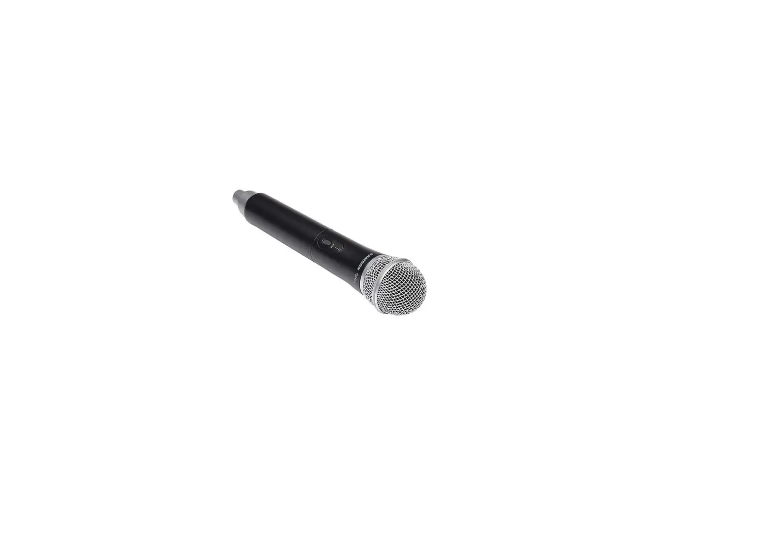
CH288 handheld transmitter with Q6 dynamic microphone capsule
PRO COMBO SYSTEM SYSTEM
CH288 handheld transmitter with Q6 dynamic microphone capsule CB288 belt pack transmitter
SE10 earset microphone with mini-XLR connector
ALL-IN-ONE COMBO SYSTEM SYSTEM
CH288 handheld transmitter with Q6 dynamic microphone capsule CB288 belt pack transmitter
Two LM5 lavalier microphone with mini-XLR connector Two HS5 headset microphone with mini-XLR connector
PRESENTATION SYSTEM
Two CB288 belt pack transmitters
Two LM5 lavalier microphone with mini-XLR connector Two HS5 headset microphone with mini-XLR connector
CR288 RECEIVER CALLOUTS
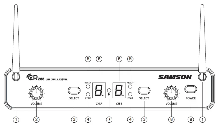
- ANTENNAS – The antenna mountings allow full rotation for optimum placement. In normal operation, both antennas should be placed in a vertical position. Both antennas can be folded inward for convenience when transporting the CR288.
- VOLUME CONTROL (CH A) – This knob sets the level of the audio signal being output through the CH A output jacks on the rear panel. Reference level is obtained when the knob is turned fully clockwise (to its “10” setting).
- SELECT BUTTON – Press this button to cycle through each receiver’s operating channels. Press and hold this button to send the channel information to the transmitter via infrared transmission.
- PEAK INDICATOR – This indicator lights red when the corresponding transmitted audio signal is overloaded.
- READY INDICATOR – This indicator lights green when the corresponding receiver channel is receiving RF signal and the system is ready to use.
- LED DISPLAY – The 7-segment LED display shows each receiver’s current operating channel. The channels are indicated by 0-9 and A-F.
- IR TRANSMITTER – During “IR SET” an infrared light is used to set the transmitter channel.
- VOLUME CONTROL (CH B) – This knob sets the level of the audio signal being output through the CH B output jacks on the rear panel. Reference level is obtained when the knob is turned fully clockwise (to its “10” setting).
- POWER SWITCH – Use this to turn the CR288 power on and off.
CR288 RECEIVER CALLOUTS
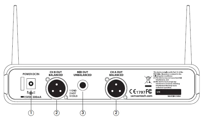
- DC INPUT – Connect the supplied power adapter here, using the strain relief as shown in the illustration below. WARNING: Do not substitute any other kind of power adapter. Doing so can cause severe damage to the CR288 and will void your warranty.
- BALANCED OUTPUT – Use this electronically balanced low impedance (600 Ohm) XLR jack when connecting the CR288 to professional (+4dBu) audio equipment. Pin wiring is as follows: Pin 1 ground, Pin 2 high (hot), and Pin 3 low (cold).
- MIX OUT UNBALANCED – Use this unbalanced high impedance (5K Ohm) ¼” jack when connecting the CR288 to consumer (-10dBV) audio equipment. The jack will carry the combined signal from receiver CH A and B. Wiring is as follows: tip hot, sleeve ground.

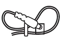
USING THE STRAIN RELIEF: Gather up a loop of wire and pass it through the strain relief, then pass the adapter plug through the loop in order to create a knot.
CB288 BELT PACK TRANSMITTER
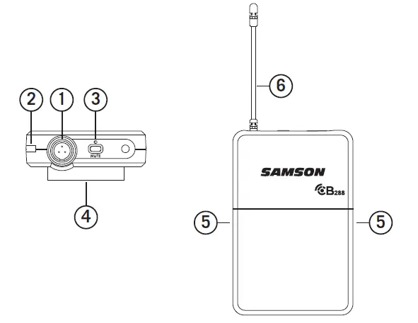
- INPUT CONNECTOR – Connect the input device via the mini-XLR connector. The CB288 is supplied with either a lavalier, headset microphone or ¼” instrument cable.
- STATUS INDICATOR – This LED displays the operation mode:
GREEN Normal Operation RED Mute Flashing GREEN Low Battery - POWER/MUTE SWITCH – Press and hold to turn the unit on or off. Press and release to mute or unmute the transmitter
- BELT CLIP – Use this clip to fasten the CB288 transmitter to a belt or guitar strap
- BATTERY COVER RELEASE – Push in both sides and pull back to open the CB288 battery cover
- ANTENNA – This permanently attached transmitter antenna should be fully extended during normal operation.
CB288 BELT PACK TRANSMITTER
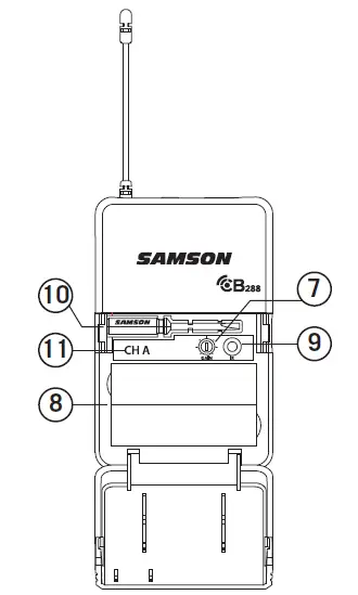
- Input GAIN Control – This control adjusts the transmitter input sensitivity to work with microphone and instruments inputs. For optimal performance, using the included screwdriver, set the input GAIN control to where you see the CR288 PEAK indicator start to light under high levels, then turn down slowly until the PEAK light stops lighting.
- Battery Holder – Insert two standard AA (LR6) batteries here, being sure to observe the plus and minus polarity markings shown. Although rechargeable Ni-Cad batteries can be used, they do not supply adequate current for more than four hours. WARNING: Do not insert the batteries backwards; doing so can cause severe damage to the CB288 and will void your warranty.
- IR LENS – This window is used to capture the infrared signal sent from the CR288 during the IR SET to channelize the transmitter.
- SCREWDRIVER – Designed for use in adjusting the CB288 input GAIN control (See #7 Input GAIN Control).
- CHANNEL DESIGNATION – Identifies the receiver channel that the belt pack syncs and transmits with.
CH288 HANDHELD TRANSMITTER
- STATUS INDICATOR – This LED displays the operation mode:
GREEN Normal Operation RED Mute Flashing GREEN Low Battery 
- POWER/MUTE SWITCH – Press and hold to turn the unit on or off. Press and release to mute or unmute the transmitter.
- BATTERY COVER – Unscrew the battery cover and slide down to open the CH288 battery compartment.
- BATTERY HOLDER – Open the battery holder by pressing the tab and lifting the cover. Insert two standard AA (LR6) batteries here, being sure to observe the plus and minus polarity markings shown. Although rechargeable Ni-Cad batteries can be used, they do not supply adequate current for more than four hours.
WARNING: Do not insert the batteries backwards; doing so can cause severe damage to the CH288 and will void your warranty. - INPUT GAIN CONTROL – This control adjusts the transmitter input sensitivity. For optimal performance, using the included screwdriver, set the input GAIN control to where you see the CR288 PEAK indicator start to light under high levels, then turn down until the PEAK light stops lighting.
- IR LENS – This window is used to capture the infrared signal sent from the CR288 during the IR SET to channelize the transmitter. The battery cover must be open and the IR Lens facing towards the receiver to load the selected channel.
- PLASTIC SCREWDRIVER – Designed for use in adjusting the CB288 input GAIN control (See #5 Input GAIN Control HH).
NOTE: The CH288 antenna cover and grill band have been color coded to easily identify its corresponding receiver channel:
CH A – Black antenna cover and black grill band CH B – Silver antenna cover and silver grill band
QUICK START
In order for your wireless system to work correctly, both the receiver and transmitter must be set to the same channel.
Follow this basic procedure for setting up and using your Concert 288 wireless system:
Physically place the CR288 receiver where it will be used, and extend the antennas vertically. The general rule of thumb is to maintain “line of sight” between the receiver and transmitter so that the person using or wearing the transmitter can see the receiver.
With the CR288 powered off, connect the included power adapter. Turn the CR288 on momentarily to confirm that the unit is receiving power. You’ll see the LED display light up. Then turn the CR288 power off.![]()
With your amplifier or mixer off and volume control all the way down, connect the CR288 receiver mix output jack to the line level input of a mixer or amplifier. Turn the Level knob on the CR288 completely counterclockwise, then turn its power on.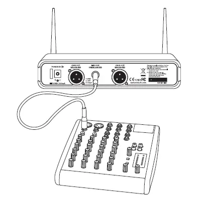
With the transmitter powered off, install two fresh AA batteries into the CB288 belt pack or CH288 handheld transmitter. Leave the battery compartment open.![]()
Turn on the power to the transmitter by pressing and holding Power switch; the indicator LED will light green.![]()
Press the CH A SELECT button on the front of the CR288 to choose an available channel for the CH A receiver. The channel number will increase by one digit, from 0-9 then A-F. Once the last channel has been reached, the count will cycle back to 0.![]()
Position the transmitter about 6-12″ (15-30 cm) from the front of the CR288 with the transmitter’s IR window facing the IR transmitter on the front panel of the CR288 receiver.![]()
Press and hold the CR288 CH A SELECT button to set the transmitter to the same channel as the receiver via infrared transmission![]()
When the transmission is complete, the CR288 will receive RF signal and the tone key from the transmitter. The CH A READY indicator will light on the front panel of the CR288 receiver. Repeat these steps for the CH![]() B transmitter and receiver. CH A and CH B available frequency channels do not overlap, so you can set the two receivers to the same channel number or letter.
B transmitter and receiver. CH A and CH B available frequency channels do not overlap, so you can set the two receivers to the same channel number or letter.
Turn on your connected amplifier or mixer, but keep the volume all the way down. Set the Volume knob on the CR288 fully clockwise (to its “10” setting). This is unity gain.![]()
Speak or sing into the microphone. Slowly raise the volume of your amplifier or mixer until the desired level is reached.
If you find the system has noticeable dropouts, reduced overall working range, or unexpected noise bursts, change the operating channel of the system using the steps above.
When using multiple systems in the same frequency band, each system must be set to a different operating channel. (See “Concert 288 Channel Plans” on page 18).
RACK MOUNTING
The CR288 receiver can be installed into a standard 19” rack for transport or permanent installation using the included rack ears. Follow the simple steps below to mount the CR288:![]()
- Attach the included rack ears by sliding each rack ear into the groove on either side of the CR288 until they lock into place, and the receiver flush with the front panel.

Position the CR288 receiver into an available rack space and slide in until the rack ears are touching the rails of the rack case and are aligned with the rack rail holes.
Mount the receiver into the rack using the appropriate size rack screws (not included). To ensure equal tension and balance when installing the receiver, you should secure screws in a crisscross pattern of opposite corners: top left -> bottom right -> top right -> bottom left - In order to mount two CR288 receivers in one rack space, the system includes a center connection piece. Slide the center connection piece into the groove of each receiver, secure using the included screws, and attach the short rack ears to each receiver. Mount the receivers into the rack using the crisscross pattern described above.

CONCERT 288 CHANNEL PLANS
| Group H 470–518 MHz | Group I 518 –566 MHz | ||||||
| CH A | Freq | CH B | Freq | CH A | Freq | CH B | Freq |
| 0 | 470.125 | 0 | 494.125 | 0 | 518.125 | 0 | 542.125 |
| 1 | 471.625 | 1 | 495.625 | 1 | 519.625 | 1 | 543.625 |
| 2 | 473.050 | 2 | 497.050 | 2 | 521.050 | 2 | 545.050 |
| 3 | 474.425 | 3 | 498.425 | 3 | 522.425 | 3 | 546.425 |
| 4 | 474.900 | 4 | 498.900 | 4 | 522.900 | 4 | 546.900 |
| 5 | 477.525 | 5 | 501.525 | 5 | 525.525 | 5 | 549.525 |
| 6 | 479.100 | 6 | 503.100 | 6 | 527.100 | 6 | 551.100 |
| 7 | 480.475 | 7 | 504.475 | 7 | 528.475 | 7 | 552.475 |
| 8 | 482.000 | 8 | 506.000 | 8 | 530.000 | 8 | 554.000 |
| 9 | 484.075 | 9 | 508.075 | 9 | 532.075 | 9 | 556.075 |
| A | 486.975 | A | 510.975 | A | 534.975 | A | 558.975 |
| B | 487.975 | B | 511.975 | B | 535.975 | B | 559.975 |
| C | 489.050 | C | 513.050 | C | 537.050 | C | 561.050 |
| D | 490.975 | D | 514.975 | D | 538.975 | D | 562.975 |
| E | 492.425 | E | 516.425 | E | 540.425 | E | 564.425 |
| F | 493.975 | F | 517.975 | F | 541.975 | F | 565.975 |
CONCERT 288 CHANNEL PLANS
| Group J* 606–654 MHz | |||
| CH A | Freq | CH B | Freq |
| 0 | 606.125 | 0 | 630.125 |
| 1 | 607.625 | 1 | 631.625 |
| 2 | 609.050 | 2 | 633.050 |
| 3 | 610.425 | 3 | 634.425 |
| 4 | 610.900 | 4 | 634.900 |
| 5 | 613.525 | 5 | 637.525 |
| 6 | 615.100 | 6 | 639.100 |
| 7 | 616.475 | 7 | 640.475 |
| 8 | 618.000 | 8 | 642.000 |
| 9 | 620.075 | 9 | 644.075 |
| A | 622.975 | A | 646.975 |
| B | 623.975 | B | 647.975 |
| C | 625.050 | C | 649.050 |
| D | 626.975 | D | 650.975 |
| E | 628.425 | E | 652.425 |
| F | 629.975 | F | 653.975 |
FAQs
A wireless microphone can broadcast how far?
The typical range for systems of the kind detailed here (10-50 mW, VHF or UHF) can range from 100 feet to 1000 feet.
Are transmitters required for wireless microphones?
The conventional “wired” microphone uses a cable to transmit its signal to the mic input and includes a male XLR output connection. Unlike a wireless microphone, which uses a radio transmitter to broadcast its output signal to a receiver before being routed to a mic input, a wireless microphone uses a receiver.
What is the operation of a wireless microphone transmitter?
In a wireless system, the audio signal entered at the microphone is converted into a radio signal that may be transferred over the air to the receiver and then turning it back into an audio signal that can be output to the rest of the sound system.
What is the purpose of a wireless transmitter?
A transmitter transmits a data signal stream wirelessly. The data is acquired by a receiver, which transmits it to your TV. It really is that simple. The wireless HDMI transmitter connects to the video or audio source device as the transmitter.
Can any receiver be used with a wireless microphone?
No, as wireless microphones may employ incompatible frequencies, exclusive noise reduction circuits, and safe 128- or 256-bit encryption, they will NOT function with any receiver.
What parts make up a system for a wireless microphone?
An input source, a transmitter, and a receiver are the key components of a professional wireless microphone system. The transmitter receives an audio signal from the input source.
What causes my wireless transmitter to malfunction?
Although it may seem elementary, make sure your batteries are new or that your devices are plugged in. Unexpectedly often, batteries fail or are inadequate.
What function does a transmitter serve?
A transmitter is an electrical component used in telecommunications to generate radio waves that are then utilized by an antenna to broadcast or transfer data. The antenna receives an application of radio frequency alternating current from the transmitter, which radiates it as radio waves.
What makes the transmitter so crucial?
All radio-communicating electronic devices, including cell phones, walkie-talkies, wireless computer networks, radio and television transmitting stations, require transmitters as essential component parts.
Why do we need a transmitter?
In several process sectors, transmitters are used to measure media flow, pressure, level, and temperature. The readings that these transmitters offer are used by the plant operators to optimize their procedures.
What strengthens a signal?
Go to a higher location. Signals can frequently be disrupted by mountains, hills, trees, and other barriers. You have a better chance of connecting with a mobile tower and getting a stronger signal by ascending higher land. Find the location of the nearest cell tower.
How can the signal quality be enhanced?
Sometimes a booster is exactly what you need. Although signal boosters come in a variety of sizes and designs, they are all intended to strengthen your signal by transmitting it through another device.


