Installation Instruction
![]()
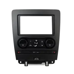
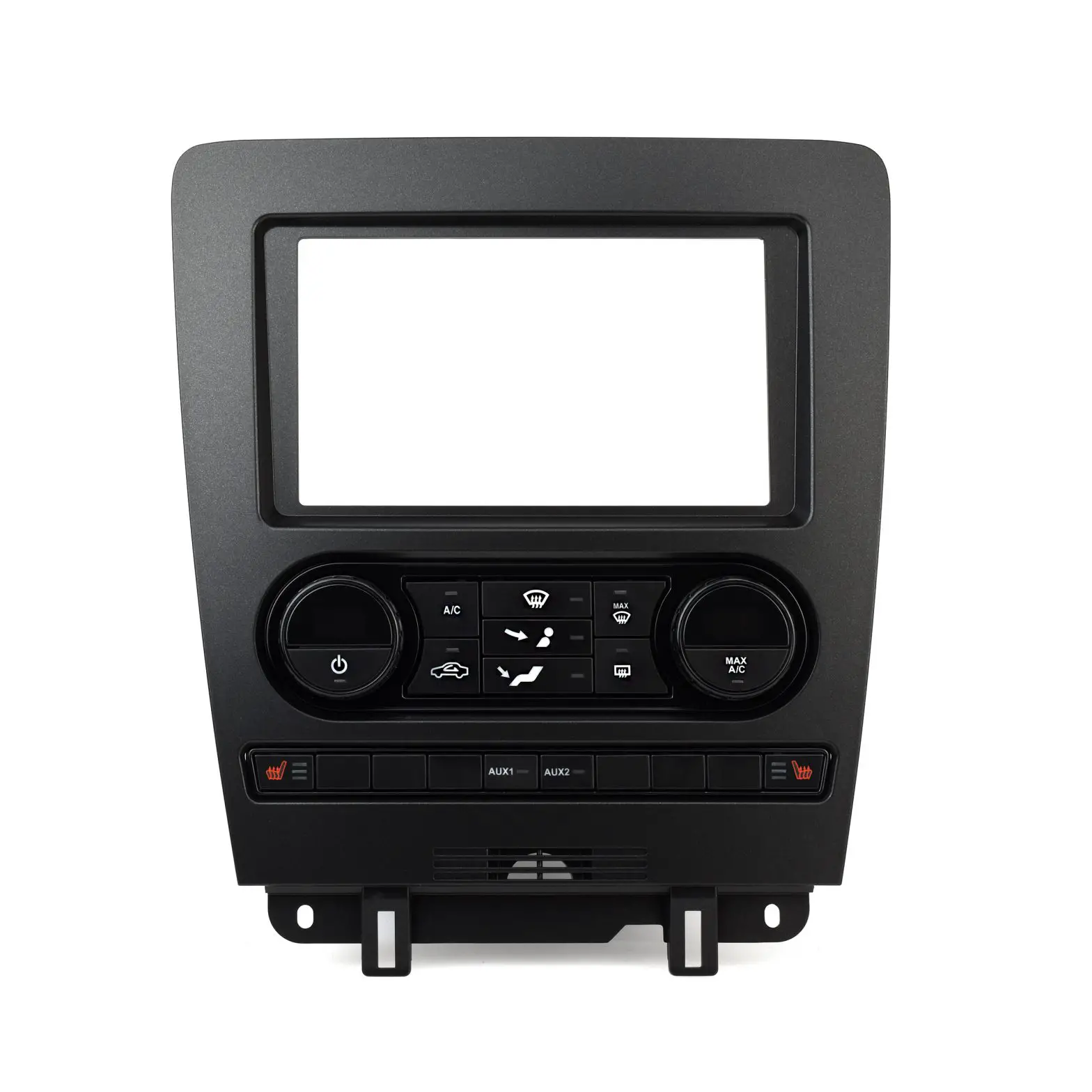
Metra 99*5853CH
Ford Mustang (†) 2010-2014
With single zone, manual climate control
Visit MetraOnline.com for more detailed information about the product and up-to-date vehicle
specific applications
KIT FEATURES
- ISO DIN radio provision with pocket
- ISO DDIN radio provision
- Included interface for climate and steering wheel functions
- Painted charcoal with a matte black center
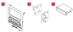
KIT COMPONENTS
- A) Radio trim panel
- B) Radio brackets
- C) Pocket
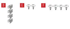
- D) (4) Panel clips
- E) (2) #8 x 3/8” Phillips pan-head screws
- F) (4) #8 x 3/8” Phillips truss-head screws
- G) Wiring harness (not shown)
- H) Antenna adapter (not shown)
WIRING & ANTENNA CONNECTIONS
Wiring Harness: Axxess interface built into kit
Antenna Adapter: Included with kit
Steering wheel control interface: Included with kit
TOOLS REQUIRED
- Panel removal tool
- Phillips screwdriver
- 9/32” socket wrench
Attention! Let the vehicle sit with the key out of the ignition for a few minutes before removing the factory radio. When testing the aftermarket equipment, ensure that all factory equipment is connected before cycling the key to ignition.
DASH DISASSEMBLY
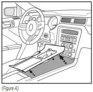
- Unclip and remove the trim panel surrounding the shifter, including the cup holders. (Figure A)

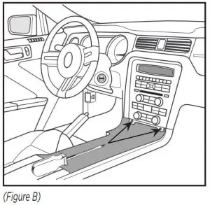
- Remove (2) 9/32” screws from the bottom of the radio/climate control panel, then unclip and remove the panel. (Figure B)

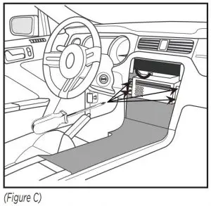
- Remove (4) Phillips screws securing the radio chassis to the vehicle. Slide the chassis out, then unplug and remove. (Figure C)
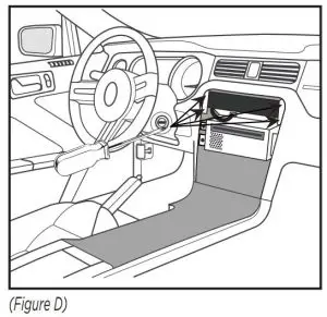
- Remove (4) Phillips screws securing the radio display to the vehicle. Slide the display out, then unplug and remove. (Figure D)
Continue to Kit Assembly
KIT ASSEMBLY
ISO DIN radio provision with pocket
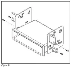
- Attach the pocket to the radio brackets using (4) #8 x 3/8” Phillips truss-head screws provided. (Figure A)

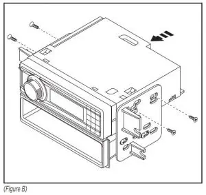
- Remove the metal DIN sleeve and trim ring from the aftermarket radio.
- Slide the radio into the bracket/pocket assembly, then secure it using screws supplied with the radio. (Figure B)
ISO DDIN radio provision
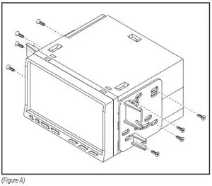
- Attach the radio brackets to the radio using screws supplied with the radio. (Figure A)
AXXESS INTERFACE INSTALLATION
INTERFACE FEATURES
- Provides accessory power (12-volt 10-amp)
- Retains R.A.P. (retained accessory power)
- Provides illumination, parking brake, reverse, and speed sense outputs
- Retains audio controls on the steering wheel
- Can be used in both amplified and non-amplified models
- Retains balance and fade
- Micro-B USB updatable
INTERFACE COMPONENTS
- Axxess interface (built into kit)
- 5853 harness
- 16-pin harness
- 3.5mm adapter
TOOLS REQUIRED
- Crimping tool and connectors, or solder gun, solder, and heat shrink
- Tape
- Wire cutter
- Zip ties
CONNECTIONS
From the 16-pin harness to the aftermarket radio, connect the:
- Red wire to the accessory wire.
- Blue/White wire to the amp turn on wire, if the vehicle is equipped with a Shaker/Shaker-Pro sound system.
- Orange/White to the illumination wire (if applicable).
- Gray wire to the right front positive speaker output.
- Gray/Black wire to the right front negative speaker output.
- White wire to the left front positive speaker output.
- White/Black wire to the left front negative speaker output.
The following (3) wires are only for multimedia/navigation radios that require these wires.
- Blue/Pink wire to the VSS/speed sense wire.
- Green/Purple wire to the reverse wire.
- Light Green wire to the parking brake wire
- Tape off and disregard the following (5) wires, they will not be used in this application: Brown, Green, Green/Black, Purple, Purple/Black
From the 5853 harness to the aftermarket radio, connect the:
- Black wire to the ground wire.
- Yellow wire to the battery wire.
- Green wire to the left rear positive speaker output.
- Green/Black wire to the left rear negative speaker output.
- Purple wire to the right rear positive speaker output.
- Purple/Black wire to the right rear negative output.
- Disregard the Red and White RCA jacks labeled “RSE/SYNC®/SAT”, they will not be used in this application.
- Disregard the Red and White RCA jacks labeled “FROM 3.5”, they will not be used in this
application. - Tape off and disregard the following (3) wires, they will not be used in this application:
Blue, Blue/White, Red. - Disregard the DIN jack, it will not be used in this application.
For models with a Shaker system:
- Connect the White RCA jack labeled “SUBWOOFER”, to the subwoofer out jack.
- Disregard the Red RCA jack labeled “CENTER CHANNEL”, it will not be used in this
application.
For models with a Shaker Pro system:
- Connect the Red RCA jack labeled “CENTER CHANNEL”, to the subwoofer out jack.
- Disregard the White RCA jack labeled “SUBWOOFER”, it will not be used in this
application.
3.5mm jack – steering wheel control retention:
The 3.5mm jack is to be used to retain audio controls on the steering wheel control.
For the radios listed below: Connect the 3.5mm adapter, to the male 3.5mm SWC jack from the 5853 harness. Any remaining wires tape off and disregard.
- Eclipse: Connect the steering wheel control wire, normally Brown, to the Brown/White wire of the connector. Then connect the remaining steering wheel control wire, normally Brown/White, to the Brown wire of the connector.
- Metra OE: Connect the steering wheel control Key 1 wire (Gray) to the Brown wire.
- Kenwood or select JVC with a steering wheel control wire: Connect the Blue/Yellow wire to the Brown wire.
Note: If your Kenwood radio auto detects as a JVC, manually set the radio type to Kenwood. See the instructions under changing radio type. - XITE: Connect the steering wheel control SWC-2 wire from the radio to the Brown wire.
- Parrot Asteroid Smart or Tablet: Connect the 3.5mm jack into the AX-SWC-PARROT (sold separately), and then connect the 4-pin connector from the AX-SWC-PARROT into the radio.
Note: The radio must be updated to rev. 2.1.4 or higher software. - Universal “2 or 3 wire” radio: Connect the steering wheel control wire, referred to as Key-A or SWC-1, to the Brown wire of the connector. Then connect the remaining steering wheel control wire, referred to as Key-B or SWC-2, to the Brown/White wire of the connector. If the radio comes with a third wire for ground, disregard this wire.
Note: After the interface has been programmed to the vehicle, refer to the manual provided with the radio for assigning the SWC buttons. Contact the radio manufacturer for more information.
For all other radios: Connect the 3.5mm jack into the port on the radio designated for an external steering wheel control interface. Refer to the manual provided with the radio if in doubt as to where the 3.5mm jack goes to.
INSTALLATION
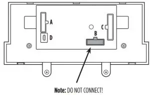
- Connect the 16-pin harness into port A.
- Disregard port B, it will not be used in this application..
- Connect the 5853 harness into port C, and then to the wiring harnesses in the vehicle.
- Port D is a Micro-B USB input for updating the interface.
PROGRAMMING
- Open the driver’s door, and keep open during the programming process.
- Cycle the ignition on and wait until the climate control lights turn blue.
Note: If the lights don’t turn blue, unplug port C from the touchscreen for a few seconds,
then try again. - Test all functions of the installation for proper operation, before reassembling the dash.
FINAL ASSEMBLY
- Slide the radio into the dash. Before doing so, remove a module from the sub-dash prohibiting the radio from sliding in, then relocate it downward. The mounting brackets
attached to the module will need to be bent outward to make room for the radio. - Secure the completed assembly to the dash using the factory screws, then reassemble the dash in reverse order of disassembly using the 99-5853CH radio trim panel.
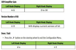
The buttons on the steering wheel will be used to enter, navigate, and make changes to the menu. The display on the climate knobs will be used to view the menu.
- With the driver’s door open, press and hold the button, then cycle the key on.
- Press the Track Up and Track Down buttons to toggle through the menu options available.
Refer to the Menu Options table for a list of options, and description of each option. - Press the Volume Up and Volume Down buttons to toggle through the sub-menu options
available. Refer to the appropriate Sub-Menu Options table for the item in interest. - Once an item has been chosen to change, press the
 button.
 - Navigate to “d o”, then press the button to exit the Configuration Menu.
- If no activity after 10-seconds the Configuration Menu will close.
Menu Options
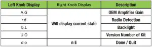
Sub-Menu Options
Radio Detection
- Press the button on the steering wheel to start the auto detection process.
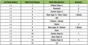
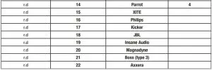
- If the steering wheel controls don’t work, change the radio type to the opposite radio type.
- If the display shows 5 (JVC), change the radio type to 2 (Kenwood).
- If the display shows Alpine, but an Alpine radio isn’t installed, make sure the 3.5mm jack is plugged in.
- AX-SWC-PARROT required (sold separately). The software in the radio must be rev. 2.1.4 or higher.
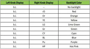
Backlight
If you are having difficulties with the installation of this product, contact our Tech Support line either by phone at 1-800-253-TECH, or email at [email protected]. Before doing so, look over the instruction booklet a second time and ensure that the installation was performed exactly as the instruction booklet is stated. Have the vehicle apart and ready to perform troubleshooting steps before contacting Metra/Axxess Tech Support.
![]() KNOWLEDGE IS POWER
KNOWLEDGE IS POWER
Enhance your installation and fabrication skills by enrolling in the most recognized and respected mobile electronics school in our industry.
Log onto www.installerinstitute.com or call 800-354-6782 for more information and take steps toward a better tomorrow.

Metra recommends MECP certified technicians
Read More About This Manual & Download PDF:
Metra 99*5853CH Installation Instruction – Download [optimized]
Metra 99*5853CH Installation Instruction – Download
Questions about your Manual? Post in the comments!


