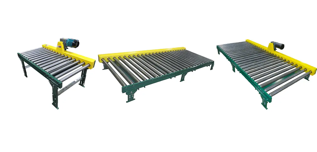
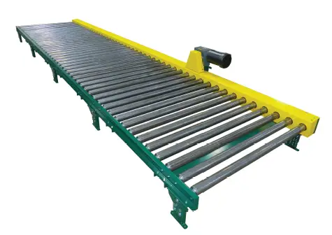
ASHLAND CDLR16F-17F Chain Driven Live Rollers
WARNING LABELS
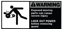
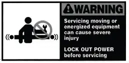
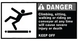
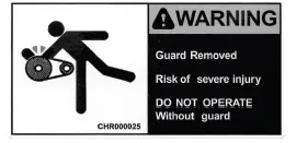
In an effort to reduce injury, warning labels have been placed at various lo cations on the conveyor. Please check for and note all labels. Make sure personnel are alerted to and follow warning labels.
- Placed on removable chain guard.

- Placed at a maximum of 20 feet both sides.

- Placed at a maximum of 20 feet both sides.

- Placed on inside of chain guard.

Receiving & Uncrating
- Examine the condition of the equipment for any damage which may have occurred during shipment or for any missing parts. Notify the carrier immediately concerning damaged or missing parts.
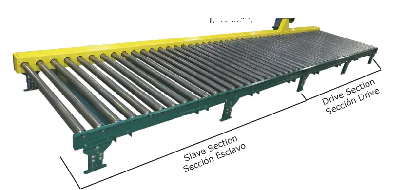
- This product is normally shipped as:
- One section if 10 feet or less
- Two or more sections if longer than 10 feet
- Drive section
- Slave sections if re quired
- All product is normally supplied on one skid
- Unpack product at area of assem bly.
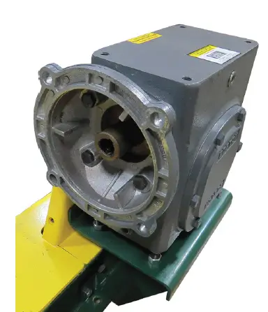
Important: The gear box (reducer) is shipped with the vent plug uninstalled. The vent plug is included with the gear box documentation and conveyor manual. Remove the solid plug and in-stall the plastic vent plug in the location shown (see lubrication section).
Installation Safety
If this product is interfaced with other conveyors, machinery, or equipment, precautions must be taken. Placing this conveyor close to other conveyors or equipment may cause a hazardous pinch point.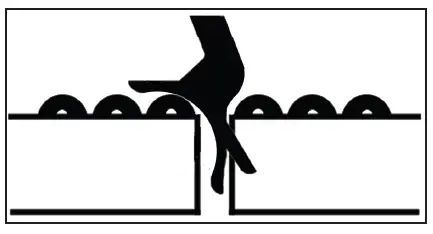
This type of installation requires a pop-out roller and bracket assembly. This helps to protect personnel from entangling limbs between the power conveyor and other pieces of equipment.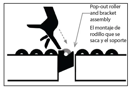
Contact an Ashland Conveyor Products’ representative to select the correct pop-out roller and bracket assembly.
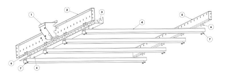
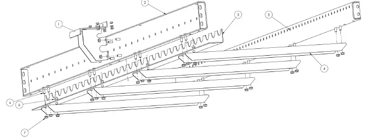
Assembly
- The drive section must be placed as close to the center of the conveyor run as possible. For example, if there are two slave sections the drive section must be placed in between the two slave sections.
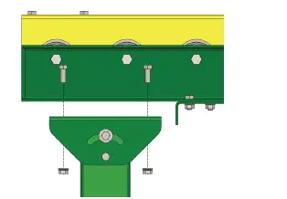
- Preassemble floor supports to the correct heights.
- Attach floor supports to both ends of conveyor drive section, and at one end of any slave sections if required. Additional supports may be required at the center of each conveyor section if live loads dictate additional supports. Tighten bolts. One support is used to span the mating ends of a drive and slave section.
- If attaching slave sections remove chain guards and remove chain end guards between sections so rollers can be chained together.
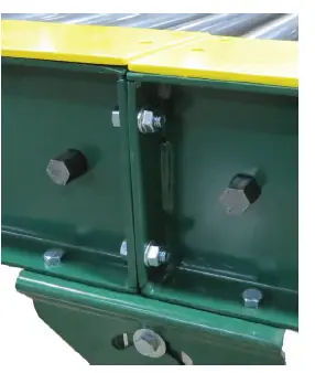
- Attach butt plates together with included hardware if the con veyor system has multiple sections.
- Adjust floor support height if necessary.

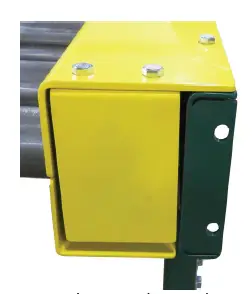
- End Support Attachment Fin

- Chain End Guard

- Slave Support Attachment

- Chain End Guard Removed

- Butt Plate Connection


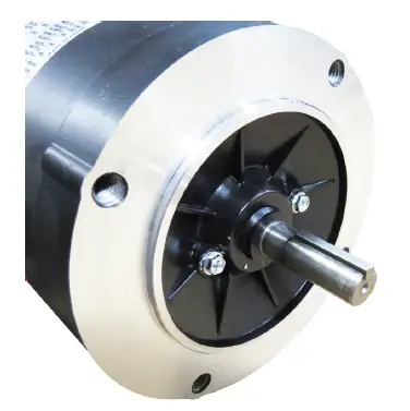
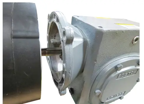
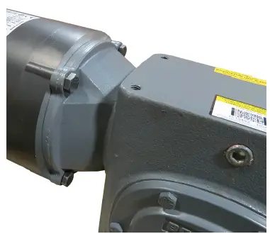
- The motor has been shipped separate from the reducer. You will find the motor in its original box. The motor was shipped separate to reduce the possibility of shipping damage. Remove the motor from the box, along with the shaft key, attaching bolts, and never-seize lubricant.
- Rub the never-seize in the reduce bore where the motor shaft will be inserted. This is to keep the motor shaft from “sticking” to the reducer incase it ever needs to be removed.
- Insert the motor key into the motor keyway, align motor shaft to reduce and slide the motor onto the reducer. Line-up the mounted holes, insert bolts, and tighten.
- Motor rotation is determined when wired. The electrician will be able to reverse the motor rotation if necessary.
- Reducer as Shipped Without Motor Attached

- Motor Shaft with Key Placed in Keyway

- Aligning Motor to Reducer

- Motor Bolted to Reducer

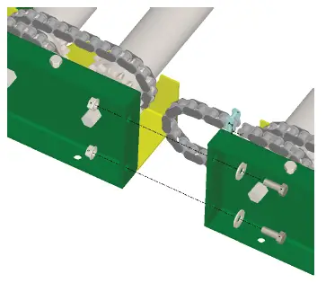
Connecting Sections
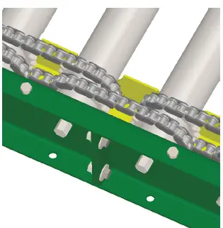
- With the chain guards removed, loop the roller chain provided with the slave section around the roller sprockets of the connecting sections.
- Connect the ends of the chain loop with the provided master link.
- Reinstall all chain guards. An chain end guard should be present at the beginning and end of the CDLR run.
- Connect Slave Section

- Loop Roller Chain Around Sprockets – Connect Master Link Loop Roller

- Installing Roller Chain Connecting Slave Section

Before Start-Up
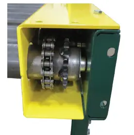
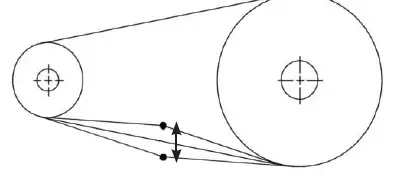
- Check the drive roller chain for proper tension. The total drive chain slackness should be about 3/8″ to 1/2″. Check sprocket alignment by placing a straight edge along face of sprock-ets, adjust if necessary by loosening set screws.
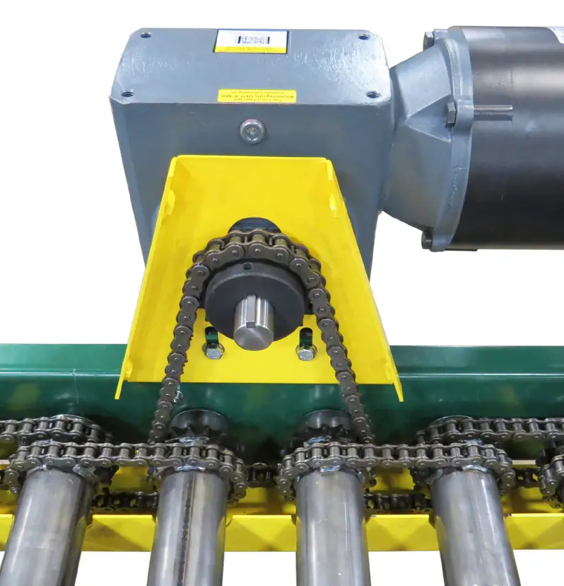
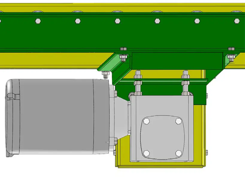
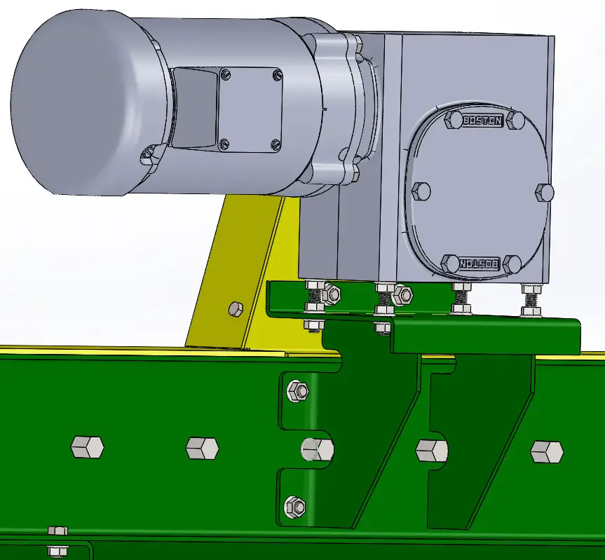
- Adjust drive chain tension using the four reducer base adjusting stand-offs. Loosen the two nuts and adjust accordingly to loosen or tighten the drive chain. Be sure all stand-offs are adjusted evenly. Tighten nuts when finished. Reinstall chain guard(s).
- Measuring Total Chain Slackness

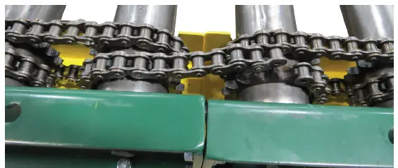
- View of Drive Chain (guard removed)

- Adjusting Drive Chain – Underslung Drive

- Adjusting Drive Chain – Overhead Drive

- Measuring Total Chain Slackness
- Check that the conveyor run is level & straight. Use surveyor’s line (string) to check straightness.
- Tighten all connector plates and floor supports. Lag supports to floor using 3/8″ lags.
- Check lubrication as noted in the Lubrication Section.
- Install electrical controls. Note voltage and phase of motor. Wiring and controls shall conform to National Electric Code and any appli-cable OSHA re quirements.
- After power supply has been connected make sure all power has been disconnected and locked out according to OSHA guidelines when further adjustments or maintenance is required.
Lubrication
Bearings
Bearings are supplied sealed and lubricated. No futher lubrication is required.
Chain
Overall, clean high-quality, non-detergent, petroleum-based or synthetic oil is best. Lube that is too viscous (such as grease) cannot penetrate the critical pin-bushing joint. Properly lubricated chains minimize corrosion due to exposure and maximize chain life by avoiding direct metal-to-metal contact. Roller chain should never be dry to the touch. See table for recommended oil weight.
- Ambient Temperature : 15o-35oF 35o-105oF 105o-120oF
- Oil Weight : SAE10 SAE20 SAE30
Reducer
The reducer is shipped pre lubricated with the vent plug uninstalled. Remove the solid plug and install the plastic vent plug as shown. Not installing the vent plug will void the reducer warranty.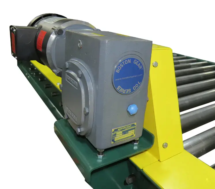
Remove solid plug and install plastic vent plug after conveyor is set-up and before operating.
The vent location is the same for underslung drives.
Planned Maintenance
| Component | Suggested Action | Frequency |
| Reducer | Check Oil Level | Refer to manufacturer’s recom- mendation |
| Change Oil | ||
| Drive Roller Chain | Check Tension | Quarterly |
| All Roller Chains | Lubricate | Monthly |
| Check for Wear | Quarterly | |
| Sprockets | Check for Wear | Quarterly |
| Check Set Screws & Keys of Reducer Sprocket | Quarterly | |
| Check Drive Sprocket Alignment | Quarterly | |
| Sprocketed Rollers | Replace Bent or Dented Rollers | Monthly |
| Structural | General Check: Tighten all Loose Bolts | Monthly |
Note: Check drive chain tension and sprocket set screws for tightness after the first 24 hours of operation
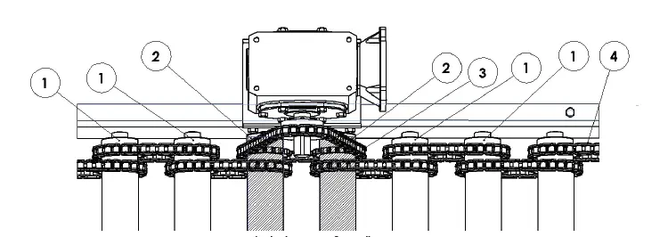
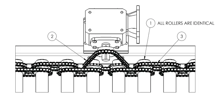
Spare Parts for 16F CDLR Standard Construction
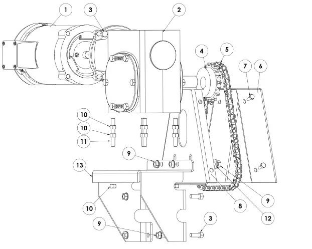
| Item | Part Number | Description | Qty |
| 1 | 60635 | MTR1HPID230/46056C1800 | 1 |
| 2 | 49772 | RED 40:1 F726 40 KT B5 G 1 | 1 |
| 3 | 10616 | BOLTHEX3/8-16X1ZG5 | 10 |
| 4 | 10406 | SPKT 50BS18 1.125 | 1 |
| 5 | 49766 | ROLLER CHAIN NO 50 53P | 1 |
| 6 | 49757 | DG CDLR FRT CVR P | 1 |
| 7 | 10595 | BOLT HEX 1/4-20 .75 Z | 4 |
| 8 | 49747 | DG CDLR BCK PLT WN P | 1 |
| 9 | 10631 | NUTHEX3/8-16FLGLKZ | 6 |
| 10 | 37467 | NUT 3/8-16 HEX Z | 12 |
| 11 | 49746 | SCR SET CUP PNT 3/8-16 2.75Z | 4 |
| 12 | 10669 | WASHER3/8FLATZ | 2 |
| 13 | 54053 | CDLR RED MNT BRKT F715-F726 | 1 |
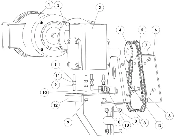
| Item | Part Number | Description | Qty |
| 1 | 60635 | MTR1HPID230/46056C1800 | 1 |
| 2 | 25992 | RED 30:1 F724 30 KT B5 G 3 | 1 |
| 3 | 10616 | BOLTHEX3/8-16X1ZG5 | 10 |
| 4 | 60452 | SPKT 40BS19 1.125 | 1 |
| 5 | 60362 | ROLLER CHAIN NO 40 58P | 1 |
| 6 | 60446 | DG CDLR FRT CVR 1.9 4C6C P | 1 |
| 7 | 10595 | BOLT HEX 1/4-20 .75 Z | 4 |
| 8 | 60382 | DG CDLR BCK PLT WN 1.9 4C6C | 1 |
| 9 | 37467 | NUT 3/8-16 HEX Z | 12 |
| 10 | 10631 | NUTHEX3/8-16FLGLKZ | 6 |
| 11 | 49746 | SCR SET CUP PNT 3/8-16 2.75Z | 4 |
| 12 | 50970 | CDLR RED MNT 17F F721 F724 | 1 |
| 13 | 10669 | WASHER3/8FLATZ | 2 |
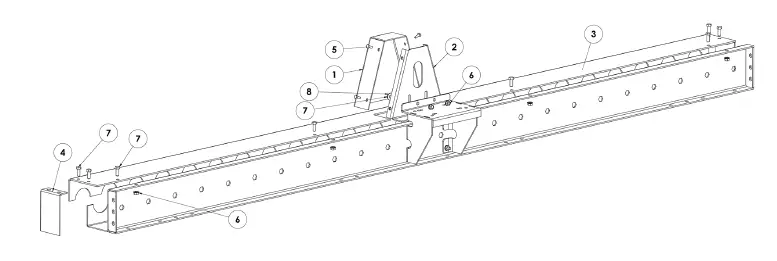
| Item | Part Number | Description | Qty |
| 1 | 54053 | CDLR RED MNT BRKT F715-F726 | 1 |
| 2 | 49753 | C 6X1.5 8GA11/16X05 120 BP P | 1 |
| 3 | 49756 | CD CG 5C 2.5R 120 B P | 1 |
| 4 | CD CB 1-1/2X5 8GA BF P | 4 | |
| 5 | 49754 | C 4X1.5 8GA11/16X05 120 BP P | 1 |
| 6 | 10616 | BOLTHEX3/8-16X1ZG5 | 18 |
| 7 | 10631 | NUTHEX3/8-16FLGLKZ | 18 |
Parts for 60″ Frame
| Item | Part Number | Description | Qty |
| 2 | 49753 | C 6X1.5 8GA11/16X05 60 BP P | 1 |
| 3 | 49998 | C 4X1.5 8GA11/16X05 60 BP P | 1 |
| 5 | 49997 | CD CG 5C 2.5R 60 B P | 1 |
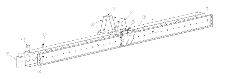
| Item | Part Number | Description | Qty |
| 1 | 50970 | CDLR RED MNT 17F F721 F724 | 1 |
| 2 | 60375 | C 5.5X1.5 8GA7/16X04 120 BP P | 1 |
| 3 | 60449 | CD CG 4C 1.9R 120 T DR P | 1 |
| 4 | CD CB 1-1/2X5 8GA BF1.9P | 4 | |
| 5 | 60377 | C 3.5X1.5 8GA7/16X04 120 BP P | 1 |
| 6 | 10616 | BOLTHEX3/8-16X1ZG5 | 20 |
| 7 | 10631 | NUTHEX3/8-16FLGLKZ | 20 |
Parts for 60″ Frame
| Item | Part Number | Description | Qty |
| 2 | 60363 | C 5.5X1.5 8GA7/16X04 60BP P | 1 |
| 3 | 60454 | CD CG 04C 1.9R 60 B P | 1 |
| 5 | 60365 | C 3.5X1.5 8GA7/16X04 60BP P | 1 |
| Item | Part Number | Description | Qty |
| 1 | 49757 | DG CDLR FRT CVR P | 1 |
| 2 | 49747 | DG CDLR BCK PLT WN P | 1 |
| 3 | 49755 | CD CG 5C 2.5R 120 T DR P | 1 |
| 4 | 49726 | CD CG END CAP P | 2 |
| 5 | 10595 | BOLT HEX 1/4-20 .75 Z | 4 |
| 6 | 10631 | NUTHEX3/8-16FLGLKZ | 6 |
| 7 | 10616 | BOLTHEX3/8-16X1ZG5 | 10 |
| 8 | 10669 | WASHER3/8FLATZ | 2 |
Parts for 120″ Non Drive Guards
| Item | Part Number | Description | Qty |
| 3 | 49759 | CD CG 5C 2.5R 120 T ND P | 1 |
Parts for 60″ Drive Guards
| Item | Part Number | Description | Qty |
| 3 | 50007 | CD CG 5C 2.5R 60 T DR P | 1 |
| 6 | 10631 | NUTHEX3/8-16FLGLKZ | 4 |
| 7 | 10616 | BOLTHEX3/8-16X1ZG5 | 8 |
Parts for 60″ Non Drive Guards
| Item | Part Number | Description | Qty |
| 3 | 50079 | CD CG 5C 2.5R 60 T ND P | 1 |
| Item | Part Number | Description | Qty |
| 1 | 60446 | DG CDLR FRT CVR 1.9 4C6C P | 1 |
| 2 | 60382 | DG CDLR BCK PLT WN 1.9 4C6C | 1 |
| 3 | 60449 | CD CG 4C 1.9R 120 T DR P | 1 |
| 4 | 50634 | CD CG 3 END CAP P | 2 |
| 5 | 10595 | BOLT HEX 1/4-20 .75 Z | 4 |
| 6 | 10631 | NUTHEX3/8-16FLGLKZ | 6 |
| 7 | 10616 | BOLTHEX3/8-16X1ZG5 | 10 |
| 8 | 10669 | WASHER3/8FLATZ | 2 |
Parts for 120″ Non Drive Guards
| Item | Part Number | Description | Qty |
| 3 | 60456 | CD CG 4C 1.9R 120 T ND P | 1 |
Parts for 60″ Drive Guards
| Item | Part Number | Description | Qty |
| 3 | 60453 | CD CG 4C 1.9R 60 T DR P | 1 |
| 6 | 10631 | NUTHEX3/8-16FLGLKZ | 4 |
| 7 | 10616 | BOLTHEX3/8-16X1ZG5 | 8 |
Parts for 60″ Non Drive Guards
| Item | Part Number | Description | Qty |
| 3 | 60455 | CD CG 4C 1.9R 60 T ND P | 1 |
| Item | Part Number | Description | Qty |
| 1 | S_ _ CO GP FTS 2-50A17 * | ||
| 2 | S_ _ AB1 2-50A17 * | 2 | |
| 3 | 49766 | ROLLER CHAIN NO 50 53P | 1 |
| 4 | 49749 | ROLLER CHAIN NO 50 33P |
- Dependent on BF of frame
| Item | Part Number | Description | Qty |
| 1 | KD CO GP TS 2 40A18* | ||
| 2 | 60362 | ROLLER CHAIN NO 40 58P | 1 |
| 3 | 60331 | ROLLER CHAIN NO 40 34P |
- Dependent on BF of frame
Trouble Shooting
Trouble: Cause: Solution
- Conveyor will not start.
- Motor overloaded
- Check for overloading of conveyor.
- Motor overloaded
- Drive chain & sprockets wear excessively.
- Lack of lubrication.
- Poor alignment.
- Loose chain.
- Replace chain and sprockets, provide lubrication.
- Align sprockets.
- Tighten chain correctly.
- Motor or reducer over-heating.
- Conveyor overloaded.
- Low voltage to motor.
- Low lubricant in reducer.
- Reduce load.
- Have electrician check as necessary.
- Lubricate per manufacturers rec ommen-dations.
Phone 800-587-0045
Fax 419-281-1096
F.O.B. Ashland, Ohio 44805
www.ashlandconveyor.com


