
ALLEGRO APM81911 Evaluation Board Module

Product Information
The APM81911 Evaluation Board is an electronic device designed to help system designers evaluate the operation and performance of the APM81911 synchronous buck regulator ClearPower module. It allows for the configuration of output voltage with a jumper for either 5 V or 3.3 V. The evaluation board has six configuration jumpers that enable different operating modes of the APM81911.
Features
- Input Operating Voltage: 3.5 V to 36 V
- Output Current*: 0 A to 3 A
- Switching Frequency and SYNCIN Frequency: 1 MHz to 2.15 MHz
- Output voltage selectable with jumper for either 5 V or 3.3 V
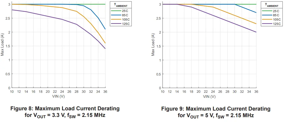
*Note: Maximum output current may be lower due to thermal limitations of the APM81911 and the APM81911 Evaluation Board at certain operating conditions.
Product Usage Instructions
To use the APM81911 Evaluation Board, follow the steps below:
- Connect a power supply using banana cables to the VIN and GND through hole banana jack or with test leads to the VIN and GND test points for power input.
- Install all configuration jumpers prior to power-on, unless using an external EN signal or SYNCIN signal where jumper J1 or J5 must be uninstalled, respectively. Refer to Table 3 for jumper descriptions.
- The APM81911 datasheet contains detailed information on the use and functionality of each pin and should be consulted for more detailed information than is contained in this user guide.
- To select the output voltage, install the jumper at 5V for 5 V output or uninstall/install at 3.3V for 3.3 V output.
Note: For more detailed information on the connections and configuration options of the APM81911 Evaluation Board, refer to Figure 2 and Table 4 for test point descriptions in the user manual.
DESCRIPTION
The APM81911 Evaluation Board is designed to help system designers evaluate the operation and performance of the APM81911 synchronous buck regulator ClearPower module. The APM81911 evaluation board output voltage can be configured with a jumper for 5 V or 3.3 V.
FEATURES
- APM81911 buck converter power module
- User-selectable output voltage, switching frequency, lowpower mode, soft-start time, clock source, and output clock state
- Banana jacks for input and output power
APM81911 Evaluation Board Configurations
Table 1: APM81911 Evaluation Board Configurations
| Configuration Name | Part Number | Output Voltage |
| APM81911 | APEK81911KNB-01 | Selectable (3.3 V or 5 V) |
Table 2: General Specifications
| Specification | Min. | Nom. | Max. | Units |
| Input Operating Voltage | 3.5 | – | 36 | V |
| Output Current* | 0 | – | 3 | A |
| Switching Frequency and SYNCIN Frequency | 1 | – | 2.15 | MHz |
*Maximum output current may be lower due to thermal limitations of the APM81911 and the APM81911 Evaluation Board at certain
operating conditions.
USING THE EVALUATION BOARD
This section provides an overview of the connections and configuration options of the APM81911 Evaluation Board. Each group of
connections highlighted in Figure 2 has a detail section below. The default jumper positions are highlighted in green. The APM81911
datasheet contains detailed information on the use and functionality of each pin and should be consulted for more detailed information
than is contained in this user guide.
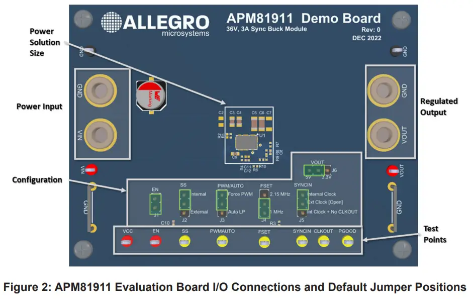
Power Input
Connect a power supply using banana cables to the VIN and GND through hole banana jack or with test leads to the VIN and GND
test points.
Device Configuration
There are six configuration jumpers on the evaluation board to exercise different operating modes of the APM81911. All configuration jumpers must be installed prior to power-on, unless using an external EN signal or SYNCIN signal where jumper J1 or J5 must be
uninstalled, respectively.
Table 3: Jumper Descriptions
| Jumper | Name | Description |
| J1 | EN | Install to tie EN to VIN and enable the APM81911 when VIN is above UVLO. Uninstall to control EN through an external signal at the EN test point. |
| J2 | SS | Soft-start select. Install at “Internal” to use internal soft-start or “External” to use the external 47 nF soft-start capacitor. |
| J3 | PWM/AUTO | Low-power mode select. Install at “Auto LP” to allow the part to enter low-power mode under light loads. Install at “Force PWM” to always stay in PWM switching mode. |
| J4 | FSET | Frequency Set select. Install at “2.15 MHz” or “1 MHz”. The “2.15 MHz” option ties FSET to VCC and the “1 MHz” option ties FSET to GND through a resistor. |
| J5 | SYNCIN | Clock synchronization input. Install from center pin to top “Internal Clock” pin to use the internal clock and enable the CLKOUT pin. Install from center pin to the bottom “Int Clock + No CLKOUT” to use the internal clock and disable the CLKOUT signal. Leave the jumper open to apply a synchronization clock at the SYNCIN test point. |
| J6 | VOUT | Output voltage select. Install at “5V” for 5 V output. Uninstall or install at “3.3V” for 3.3 V output. |
Table 4: Test Point Descriptions
| Test Point | Description |
| VIN | Positive terminal for input voltage connection or sensing. |
| VOUT | Positive terminal for output voltage connection or sensing. |
| GND | Negative terminal for voltage input/output or sensing. |
| VCC | VCC pin voltage monitor test point. |
| EN | EN pin voltage monitor or external logic input. Uninstall J1 to use an external enable signal on the EN test point. |
| SS | Soft-start pin voltage monitor test point. |
| FSET | FSET voltage monitor test point. |
| PWMAUTO | PWM/AUTO voltage monitor test point. |
| SYNCIN | SYNCIN test point for connecting external PWM signal for clock synchronization. |
| CLKOUT | Clock monitor test point for CLKOUT signal if SYNCIN jumper is configured to enable CLKOUT. |
| PGOOD | PGOOD monitor test point. This pin is pulled up to VCC and asserts low to indicate the output is out of regulation. |
PERFORMANCE DATA
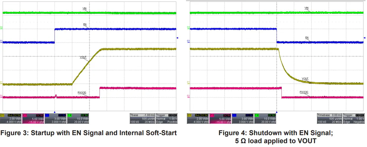
Startup and Shutdown
Load Transient Response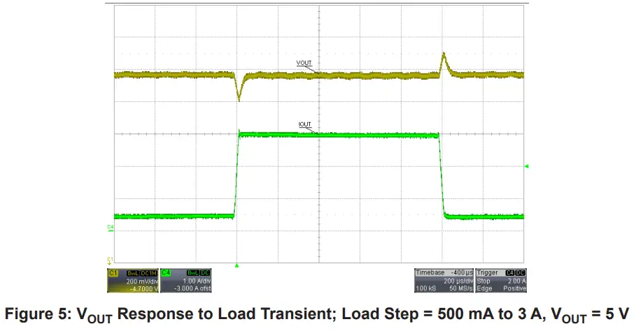
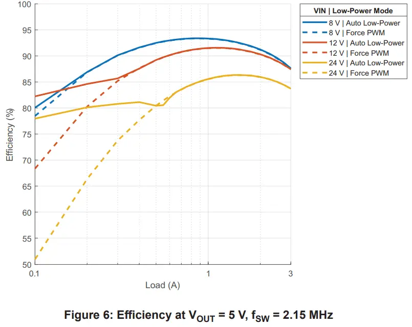
Efficiency
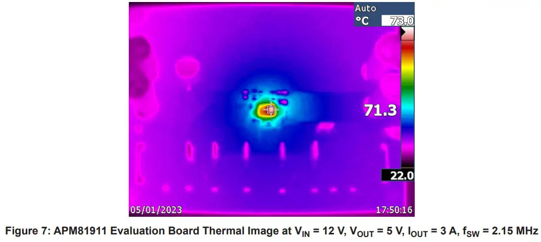
Thermal Performance
The following figure shows the thermal performance of the APM81911 Evaluation Board after five minutes of continuous operation
with ambient temperature near 25°C.
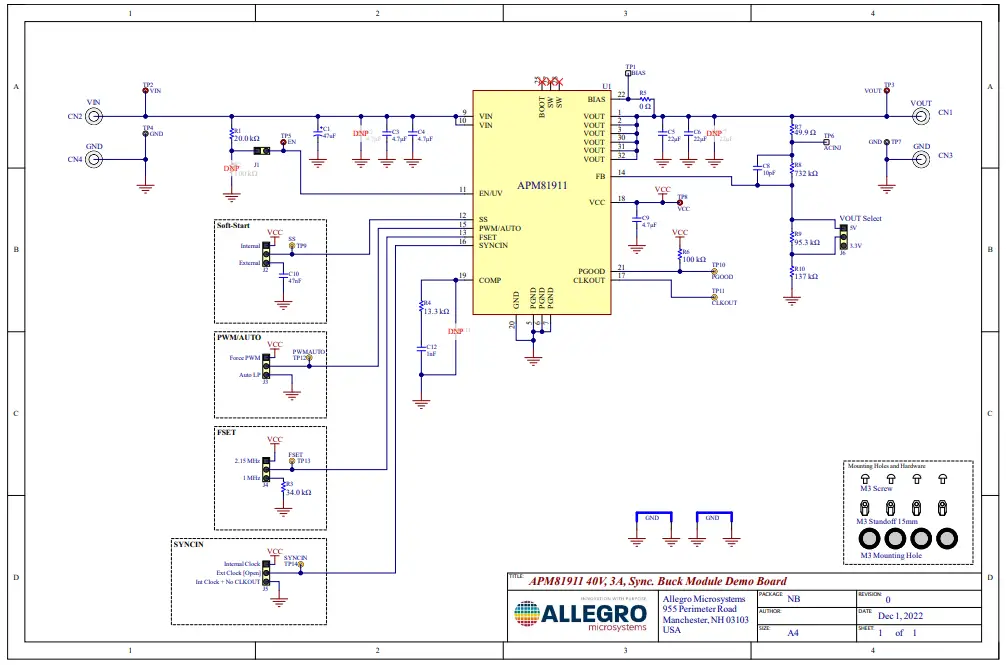
SCHEMATIC
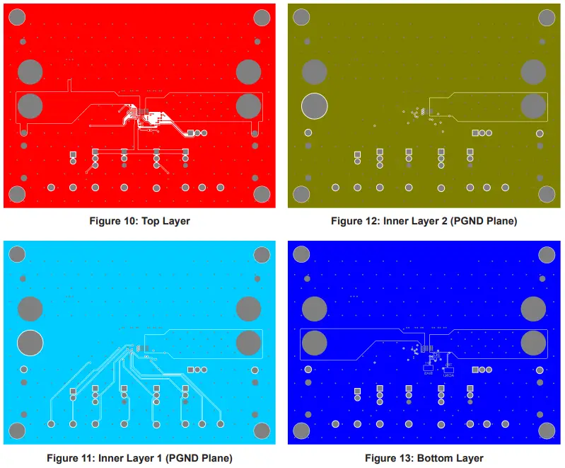
PCB LAYOUT
BILL OF MATERIALS
Table 5: APEK81911 Bill of Materials
| Designator | Description | Quan- tity | Manufacturer | Manufacturer Part Number |
| Electrical | ||||
| C1 | Capacitor, Electrolytic, 47 µF, 50 V, 8 mm | 1 | Nichicon | UUX1H470MNL6GS |
| C3, C4 | CAP CER 4.7 µF, 50 V, X7S 0805 | 2 | Murata | GRM21BC71H475KE11L |
| C5, C6 | CAP CER 22 µF, 25 V, X5R 1206 | 2 | TDK | C3216X5R1E226M160AB |
| C8 | CAP CER 10 pF, 50 V, NP0 0402 | 1 | TDK | C1005NP01H100D050BA |
| C9 | CAP CER 4.7 µF, 10 V, X5R 0603 | 1 | KEMET | C0603C475M8PACTU |
| C10 | CAP CER 0.047 µF, 16 V, X7R 0402 | 1 | Murata | GRM155R71C473KA01D |
| C12 | CAP CER 1000 pF, 50 V, NP0 0402 | 1 | Murata | GRM1555C1H102GA01D |
| R1 | Resistor, 20.0 kΩ,1/16 W, 1%, 0402 | 1 | Yageo | RC0402FR-0720KL |
| R3 | Resistor, 34.0 kΩ,1/16 W, 1%, 0402 | 1 | Yageo | RC0402FR-0734KL |
| R4 | Resistor, 13.3 kΩ,1/16 W, 1%, 0402 | 1 | Yageo | RC0402FR-0713K3L |
| R5 | Resistor, 0 Ω,1/10 W, Jumper, 0603 | 1 | Yageo | RC0603JR-070RL |
| R6 | Resistor, 100 kΩ,1/16 W, 1%, 0402 | 1 | Yageo | RC0402FR-07100KL |
| R7 | Resistor, 49.9 Ω,1/16 W, 1%, 0402 | 1 | Yageo | RT0402FRE0749R9L |
| R8 | Resistor, 732 kΩ,1/16 W, 1%, 0402 | 1 | Yageo | RC0402FR-07732KL |
| R9 | Resistor, 95.3 kΩ,1/16 W, 1%, 0402 | 1 | Yageo | RC0402FR-0795K3L |
| R10 | Resistor, 137 kΩ,1/16 W, 1%, 0402 | 1 | Yageo | RC0402FR-07137KL |
| U1 | APM81911 in QFN 4 mm × 6 mm | 1 | Allegro MicroSystems | APM81911KNBATR |
| Mechanical | ||||
| CN1, CN2, CN3, CN4 | Banana Jack- Non-Insulated 0.218″ Length | 4 | Keystone Electronics | 575-4 |
| J1 | CONN HEADER VERT 2 POS 2.54 mm | 1 | Wurth Electronics | 61300211121 |
| J2, J3, J4, J5, J6 | CONN HEADER VERT 3 POS 2.54 mm | 5 | Wurth Electronics | 61300311121 |
| MS1, MS2, MS3, MS4 | PAN HEAD SCREW_M 3 × 8 mm CROSS SL | 4 | Wurth Electronics | 97790803111 |
| STND1, STND2, STND3, STND4 | Standoffs & Spacers 5.0 HEX 15.0 mm NYLON | 4 | Keystone Electronics | 25512 |
| BIAS, ACINJ | Test Point, SMT, 105 mil × 40 mil | 2 | Keystone Electronics | 5015 |
| VIN, VOUT, EN, VCC | Test Point, Red, Through Hole Mount, 1.6 mm | 4 | Keystone Electronics | 5010 |
| GND | Test Point, Black, Through Hole Mount, 1.6 mm | 2 | Keystone Electronics | 5011 |
| SS, PGOOD, CLKOUT, PWMAUTO, FSET, SYNCIN | Test Point, Yellow, Through Hole Mount, 1.6 mm | 6 | Keystone Electronics | 5014 |
| Not Fitted | ||||
| C2 | CAP CER 4.7 µF, 50 V, X7S 0805 | 0 | Murata | GRM21BC71H475KE11L |
| C7 | CAP CER 22 µF, 25 V, X5R 1206 | 0 | TDK | C3216X5R1E226M160AB |
| C11 | CAP CER 0.1 pF, 25 V, NP0 0402 | 0 | Murata | GRM1555C1ER10WA01D |
| R2 | Resistor,100 kΩ, 1/16 W, 1%, 0402 | 0 | Yageo | RC0402FR-07100KL |
- Product page: https://www.allegromicro.com/en/products/regulate/clearpower-modules/regulator-modules/apm81911
- Datasheet: https://www.allegromicro.com/-/media/files/datasheets/apm81911-datasheet.pdf
Copyright 2023, Allegro MicroSystems.
- Allegro MicroSystems reserves the right to make, from time to time, such departures from the detail specifications as may be required to permit improvements in the performance, reliability, or manufacturability of its products. Before placing an order, the user is cautioned to verify that the information being relied upon is current.
- Allegro’s products are not to be used in any devices or systems, including but not limited to life support devices or systems, in which a failure of Allegro’s product can reasonably be expected to cause bodily harm.
- The information included herein is believed to be accurate and reliable. However, Allegro MicroSystems assumes no responsibility for its use; nor for any infringement of patents or other rights of third parties which may result from its use.
- Copies of this document are considered uncontrolled documents.
ABOUT COMPANY
- Allegro MicroSystems
- 955 Perimeter Road
- Manchester, NH 03103-3353 U.S.A.
- www.allegromicro.com


