ALLEGRO APEK81800-1 Evaluation Board User Manual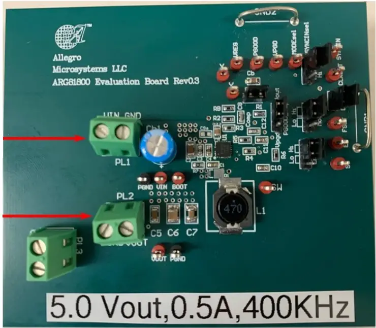
GENERAL SPECIFICATIONS
| Specification | Min | Nom. | Max. | Units |
| Absolute Maximum Input Voltage | –0.3 | − | 40 | V |
| Operating Input Voltage Range | 3.5 | 12 | 36 | V |
| VIN START Threshold, VIN rising | 3.35 | 3.55 | 3.80 | V |
| VIN STOP Threshold, VIN falling | 3.10 | 3.30 | 3.50 | V |
| Output Voltage (FB: 732k/140k, ±1%) | 4.85 | 4.98 | 5.11 | V |
| Steady-State Output Current (12 VIN) | − | 0.5 | 0.6 | A |
| Pulse-by-Pulse Current Limit @ tON(MIN) | 0.85 | 1.0 | 1.15 | A |
OPERATING INSTRUCTIONS
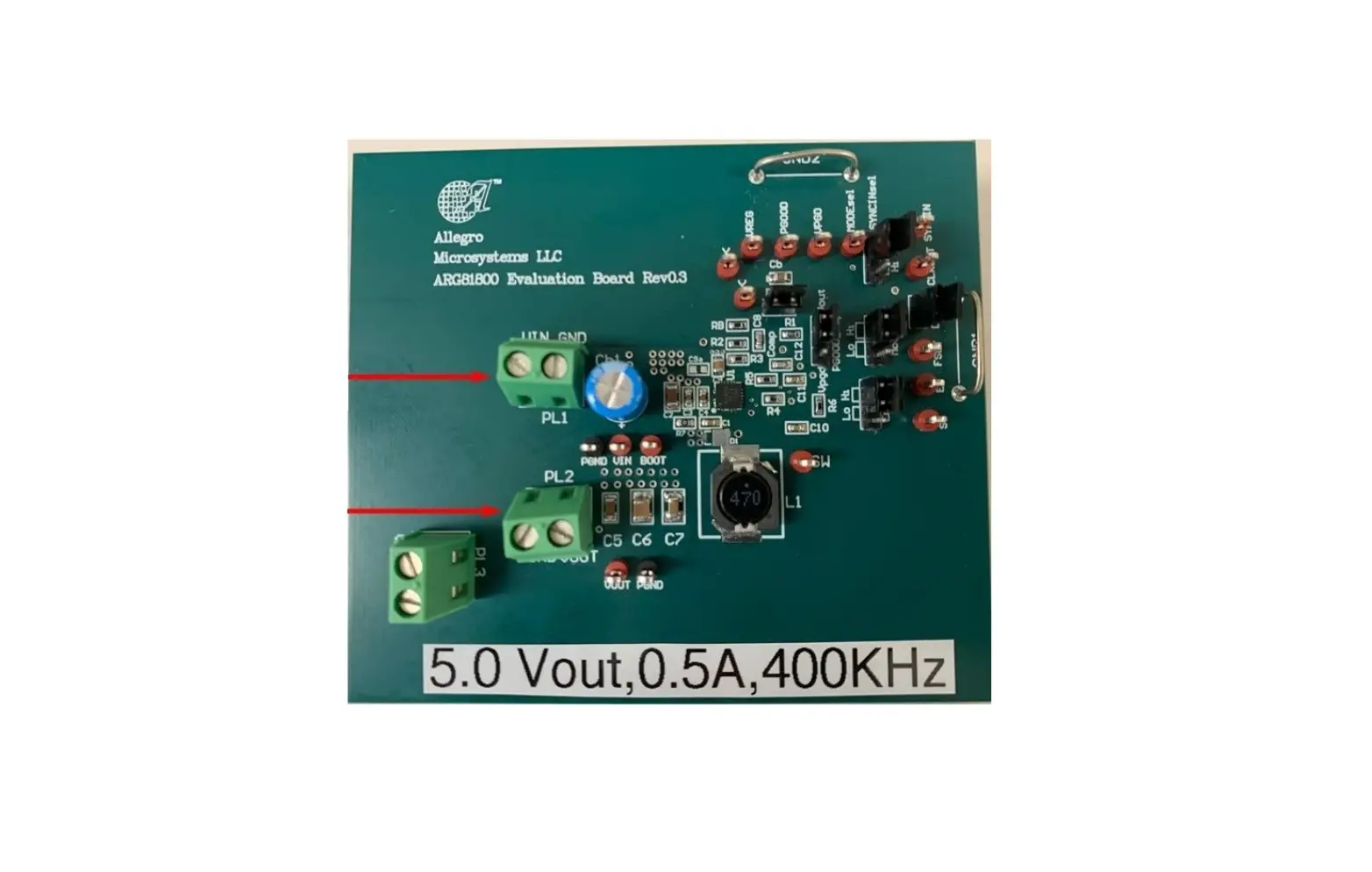
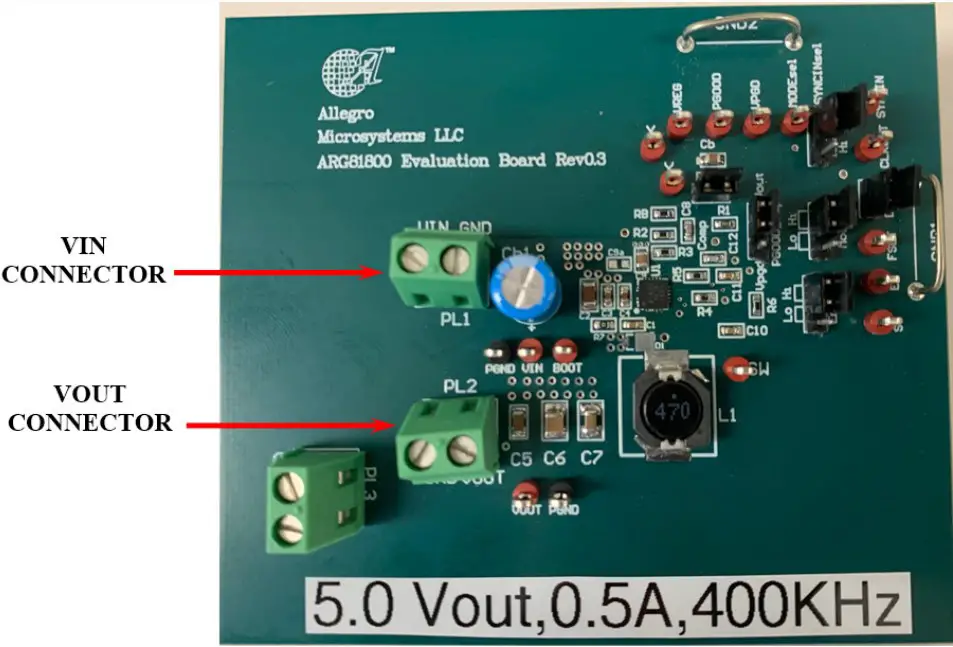
Input Power Connection:
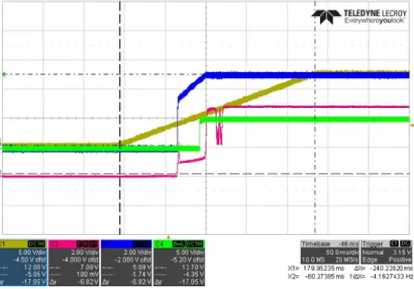
Connect a 12 V power supply from VIN to GND that is capable of at least 1 A. Once operational, VIN can fall as low as 3.55 VTYP (3.8 VMAX) before the ARG81800-1 is reset.
Output Load Connections:
Connect a load from VOUT to GND. The steady-state load current can be as high as 0.5 A. Pulse-by-pulse current limit and/or thermal shutdown will occur if the load is greater than 0.6 A.
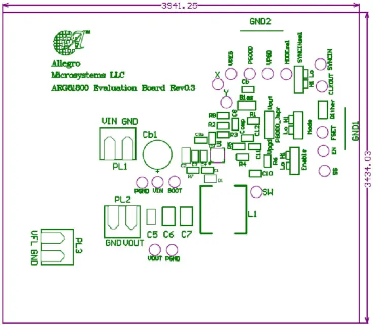
EVALUATION BOARD SCHEMATIC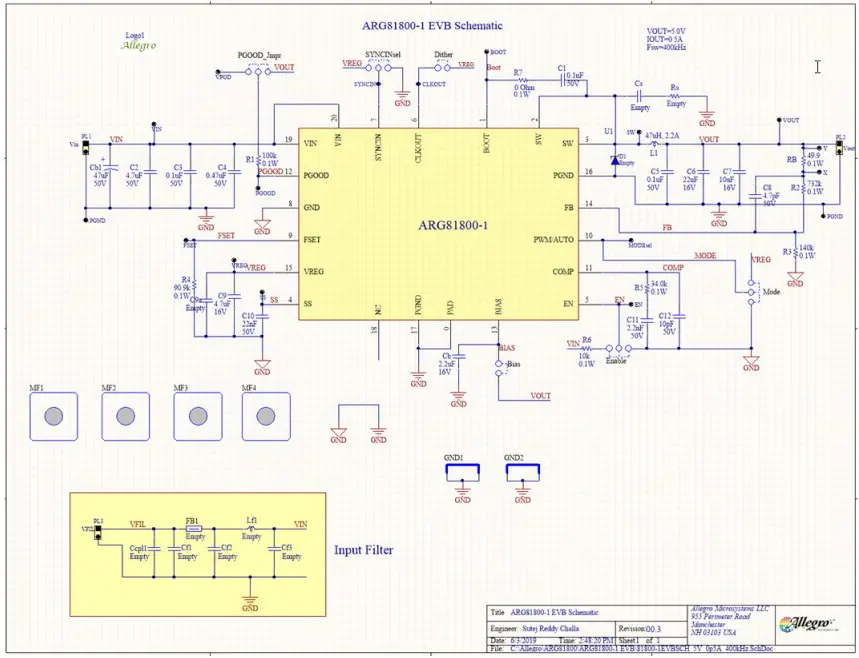
BILL OF MATERIALS
| Designator | Description | Value | Footprint | Quantity | Manufacturer | Manufacturer P/N | Source | Purchase P/N |
| C1 | Capacitor, X7R | 0.1 µF, 50 V | 0603 | 1 | Murata | GCM188R71H104KA57D | Digikey | 490-4779-2-ND |
| C2 | Capacitor, X7R | 4.7 µF, 50 V | 1206 | 1 | Murata | GRJ31CR71H475KE11L | Digikey | 490-10944-1-ND |
| C3 | Capacitor, X7R | 0.1 µF, 50 V | 0603 | 1 | Murata | GCM188R71H104KA57D | Digikey | 490-4779-2-ND |
| Cs | Capacitor, C0G (NP0) | DNP | 0603 | 0 | ||||
| Cb | Capacitor, X7R | 2.2 µF, 16 V | 0603 | 1 | Taiyo Yuden | EMK107BB7225KA-T | Digikey | 587-5835-1-ND |
| C4 | Capacitor, X7R | 0.47 µF, 50 V | 0603 | 1 | Taiyo Yuden | UMK107B7474KA-TR | Digikey | 587-3170-1-ND |
| C5 | Capacitor, X7R | 0.1 µF, 50 V | 1206 | 1 | Murata | GCM319R71H104KA37J | Digikey | 490-14745-2-ND |
| C6 | Capacitor, X7R | 22 µF, 16 V | 1210 | 1 | Murata | GRM32ER71C226MEA8L | Digikey | 490-14539-1-ND |
| C7 | Capacitor, X7R | 10 µF, 16 V | 1210 | 1 | Murata | GRM32DR71C106KA01L | Digikey | 490-1875-2-ND |
| C8 | Capacitor, C0G (NP0) | 4.7 pF, 50 V | 0603 | 1 | Murata | GCM1885C1H4R7BA16D | Digikey | 490-14430-2-ND |
| C9 | Capacitor, X7R | 4.7 µF, 16 V | 0805 | 1 | Murata | GCJ21BR71C475KA01L | Digikey | 490-10557-1-ND |
| C9a | Capacitor, X7R | DNP | 0603 | 0 | ||||
| C10 | Capacitor,X7R | 22 nF, 50 V | 0603 | 1 | Murata | GRM188R71H223KA01D | Digikey | 490-5851-1-ND |
| C11 | Capacitor, X7R | 2.2 nF, 50 V | 0603 | 1 | Murata | GCM188R71H222KA37D | Digikey | 490-4931-2-ND |
| C12 | Capacitor, C0G (NP0) | 10 pF, 50 V | 0603 | 1 | Kemet | C0603C100J5GACTU | Digikey | 399-1049-1-ND |
| Cb1 | Capacitor : Alu Electrolytic SMT | 47 µF, 50 V | 6 mm or 8 mm | 1 | Nichicon | UBT1H470MPD1TD | Digikey | 493-4507-1-ND |
| Ccpl1 | Capacitor, X7R | DNP | 0805 | 0 | ||||
| Cf1 | Capacitor, X7R | DNP | 1210 | 0 | ||||
| Cf2, Cf3 | Capacitor, X7R | DNP | 1210 | 0 | ||||
| Bias, Dither, Enable | Jumper Header : Male 2-pin | 0.1″ pitch | 3 | Omron | XJ8B-0211 | Mouser | 653-XJ8B-0211 | |
| Mode, PGOOD_Jmpr, SYNCINsel | Jumper Header : Male 3-pin | 0.1″ pitch | 3 | Molex | 22-28-5030 | Mouser | 653-XJ8B-0211 | |
| Bias, Dither, Enable, Mode, PGOOD_Jmpr, SYNCINsel | Jumper Shunt: 2 positions | 0.1″ pitch | 6 | TE Connectivity | 382811-6 | Mouser | 571-382811-6 | |
| BOOT, CLKOUT, EN, FSET, MODEsel, PGOOD, SS, SW, SYNCIN, VIN, VOUT, VPGD, VREG, X, Y | Test Points – Red | 0.063″, diameter | 15 | Keystone Electronics | 5010 | Digikey | 36-5010-ND | |
| PGND | Test Points – Black | 0.063″, diameter | 2 | Keystone Electronics | 5011 | Digikey | 36-5011-ND | |
| FB1 | Ferrite Bead : Chip Impeder | DNP | 0805 | 0 | ||||
| GND1, GND2 | Ground Bar : Tinned Copper Wire | GROUNDBAR_ 15MMP_20SWG | 2 | |||||
| L1 | Inductor | 47 µH, 2.2 A | 10 mm × 10 mm | 1 | Wurth Electronics | 7447714470 | Digikey | 732-2994-1-ND |
| Lf1 | Inductor | DNP | 8.2 mm × 8.2 mm | 0 | ||||
| MF1, MF2, MF3, MF4 | Mount Foot : Adhesive Rubber | Clear | 4 | 3M | SJ-5303 (CLEAR) | Digikey | SJ5303-7-ND | |
| PL1, PL2, PL3 | Terminal Block | 5.08 mm pitch, Vertical, 2 position | 3 | Phoenix Contact | 1715721 | Digikey | 277-1263-ND | |
| R1 | Resistor, 1%,1/10 W | 10 kΩ | 0603 | 1 | Panasonic | ERJ-3EKF1002V | Digikey | P10.0KHCT-ND |
| R2 | Resistor, 1%,1/10 W | 732 kΩ | 0603 | 1 | Panasonic | ERJ-3EKF7323V | Digikey | P732KHCT-ND |
| R3 | Resistor, 1%,1/10 W | 140 kΩ | 0603 | 1 | Panasonic | ERJ-3EKF1403V | Digikey | P140KHCT-ND |
| R4 | Resistor, 1%,1/10 W | 90.9 kΩ | 0603 | 1 | Panasonic | ERJ-3EKF7152V | Digikey | P71.5KHCT-ND |
| R5 | Resistor, 1%,1/10 W | 34.0 kΩ | 0603 | 1 | Panasonic | ERJ-3EKF3402V | Digikey | P34.0KHCT-ND |
| R6 | Resistor, 1%,1/10 W | 10 kΩ | 0603 | 1 | Panasonic | ERJ-3EKF1002V | Digikey | P10.0KHCT-ND |
| R7 | Resistor, 1%,1/10 W | 0 Ω | 0603 | 1 | Panasonic | ERJ-3GEY0R00V | Digikey | P0.0GCT-ND |
| RB | Resistor, 1%,1/10 W | 49.9 Ω | 0603 | 1 | Panasonic | ERJ-3EKF49R9V | Digikey | P49.9HCT-ND |
| Rs | Resistor, 1%, 0.25 W | DNP | 1206 | 0 | ||||
| U1 | Allegro IC | ARG81800-1 | QFN20 4×4 | 1 | Allegro | ARG81800KESJSR-1 | ||
| Label: | 5.0 Vout, 0.5 A, 400 kHz | |||||||
| DNP – Do Not Populate | ||||||||
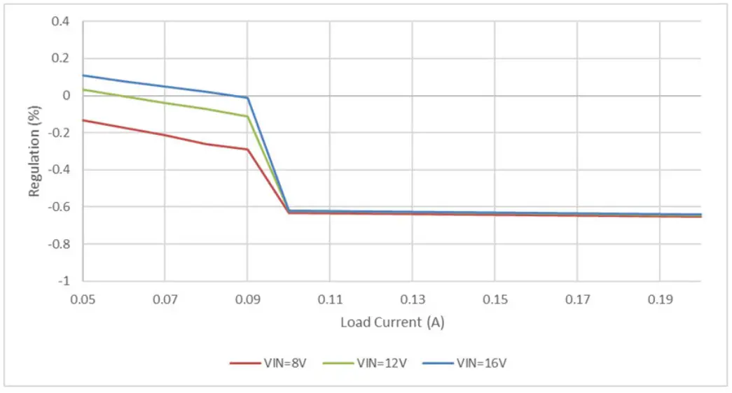
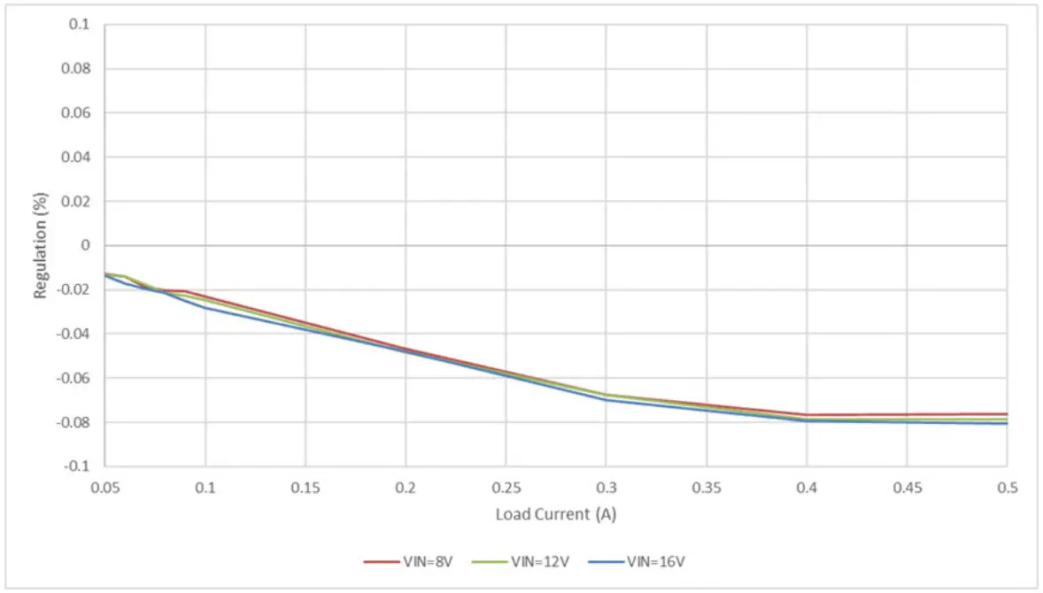
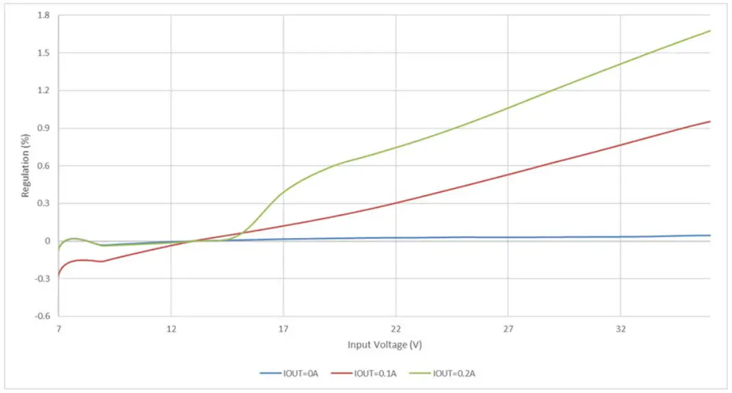
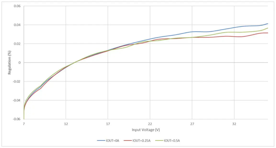
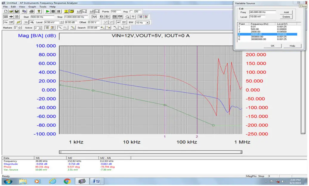
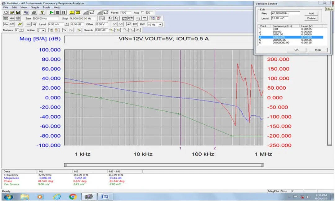
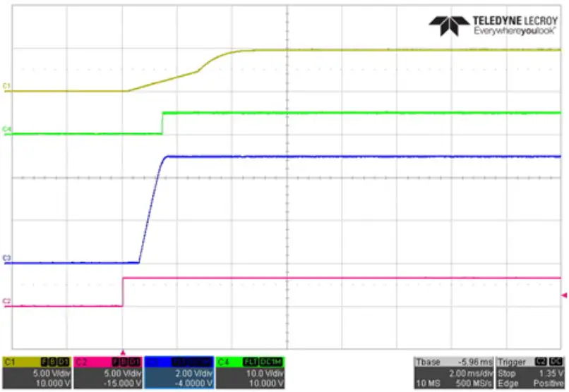
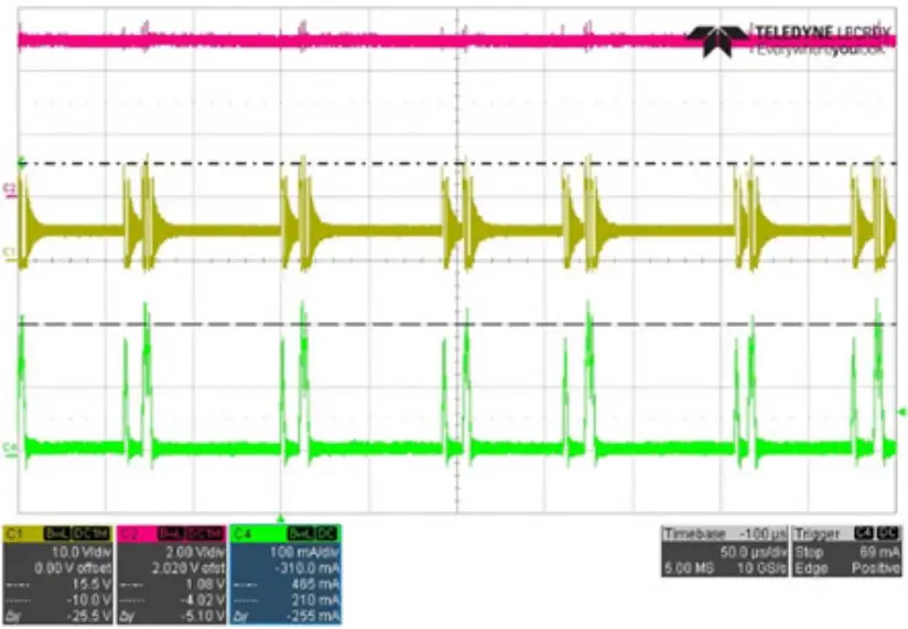
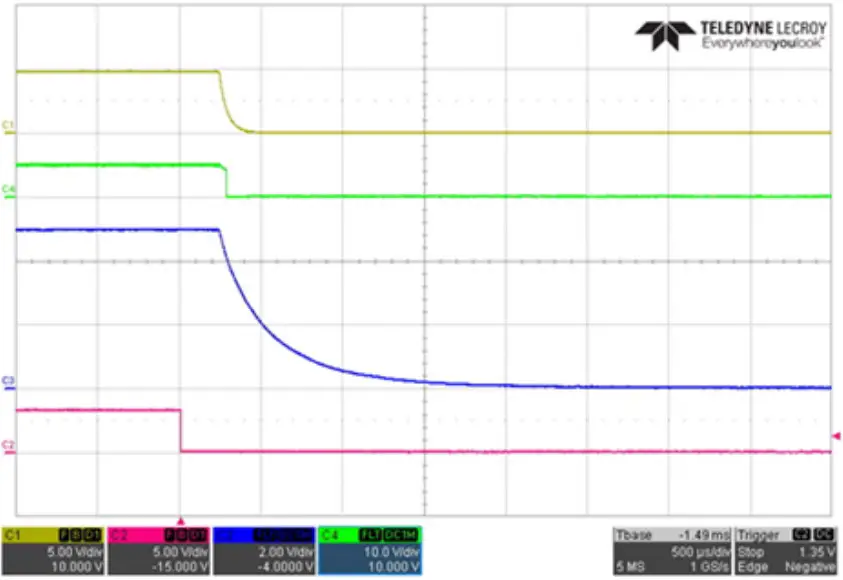
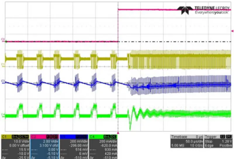
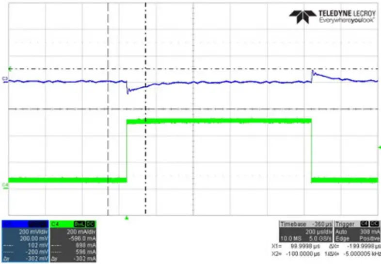
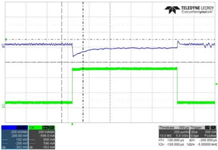
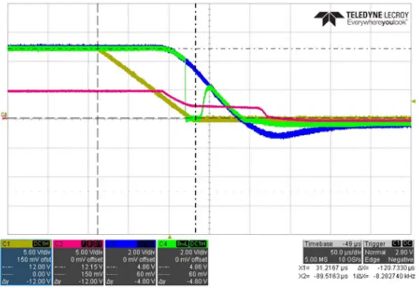
EVALUATION BOARD PERFORMANCE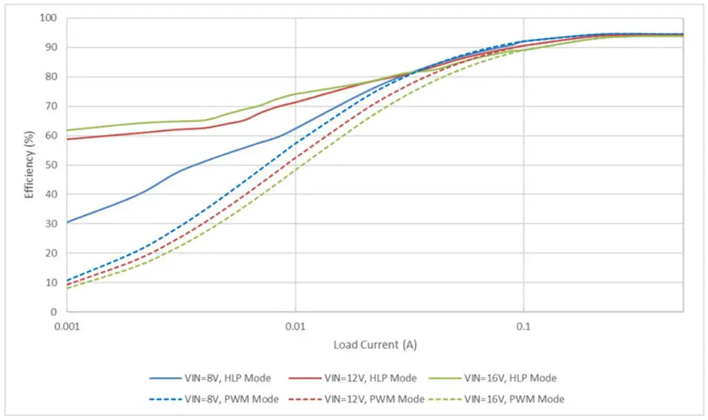
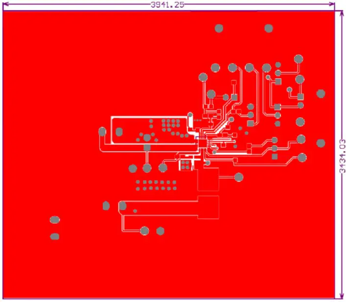
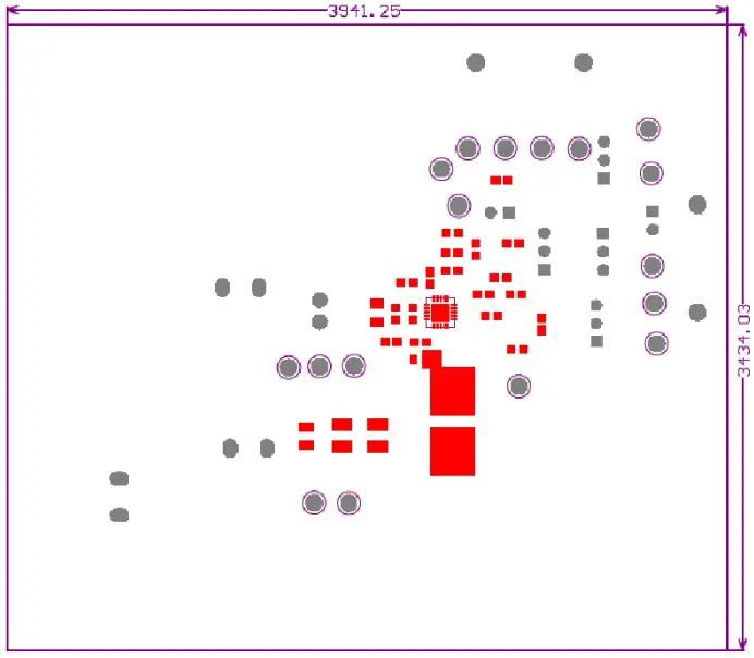
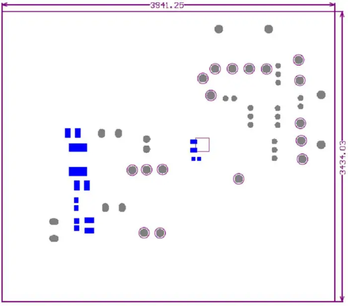
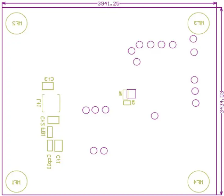
PCB LAYOUT
Revision History
| Number | Date | Description |
| – | December 16, 2019 | Initial Release |
| 1 | December 2, 2022 | Minor editorial updates |
For the latest version of this document, visit our website:
www.allegromicro.com


