![]() ASEK37002 Evaluation Board
ASEK37002 Evaluation Board
User Guide
DESCRIPTION
This user guide documents the features, operation, and use of the ACS37002 current sensor with the ASEK37002 demo board. This evaluation kit provides users with a simple means of evaluating the ACS37002 current sensor in a lab environment without the need of a custom-designed evaluation board.
FEATURES
The ACS37002 is a fully integrated Hall-effect current sensor in a SOIC16 package with 0.85 mΩ integrated conductor. The sensor is factory-trimmed to provide high accuracy over the entire operating range. A fast overcurrent alert fault output has a user-configurable threshold via an analog input pin, providing short-circuit detection and enhanced system protection. The sensor also has four programmable gain settings.
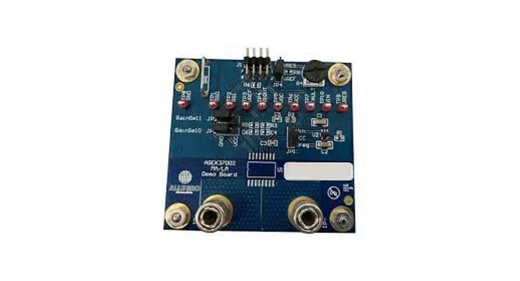
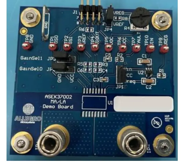 Figure 1: ASEK37002 Evaluation Board
EVALUATION BOARD CONTENTS
- ASEK37002 evaluation board
Table 1: ACS37002 Evaluation Board Configurations
| Configuration Name | Part Number | Current Sensing Range, IPR (A) | Sensitivity (mV/A) | Supply Voltage (V) |
| ASEK37002LMA-BB-3B | ACS37002LMA-BB-3B | – | – | 3.3 |
| ASEK37002LMA-BB-5B | ACS37002LMA-BB-5B | – | – | 5 |
| ASEK37002LMC-050B5 | ACS37002LMC-050B5 | ±33.3, ±40, ±50, ±66.7 | 60, 50, 40, 30 | 5 |
USING THE EVALUATION BOARD
- Prior to applying power to the ACS37002, configure the JP2 (GAIN_SEL0) and JP3 (GAIN_SEL1) shunts for the desired gain of the ACS37002.
- Apply power to the board. VCC of the ACS37002 device can be supplied directly or via an on board regulator. In either case, the user will provide power to the evaluation board through the TPVin test point. A. Powering the ACS37002 with the on-board regulator: With the JP1 shunt placed in the “Vreg” position, power is supplied to the device by the on-board regulator. To allow for the dropout voltage of the regulator, it is recommended that the voltage supplied to the TPVin test point is equal to VCC + 1 V. For example, using the 5 V on board regulator to supply a 5 V version of the ACS37002 would require a voltage of >6 V supplied to the TPVin test point. B. Powering the ACS37002 directly: with the JP1 shunt placed in the “Vin” position, power is supplied to the ACS37002 directly via the TPVin test point. In this case, the user would provide a 5 V supply to a 5 V version of the device, or a 3.3 V supply to a 3.3 V version.
- Configure JP4 to apply a voltage to the VOC pin of the ACS37002. The voltage applied to VOC selects the Overcurrent Fault trip point by applying a voltage to the VOC pin of the ACS37002. JP4 can be configured to ground VOC, apply a voltage from a resistive divider derived from Vref and the R4 potentiometer, or a directly driven voltage on the TPin test point.
- Apply a current source to the IP+ and IP- banana jacks.
- The ACS37002 output is monitored via the TPViout test point.
- The Overcurrent Fault output is monitored via the TPFLT test point.
Refer to the ACS37002 datasheet for electrical and performance specifications as well as detailed functional operation guidelines.
SCHEMATIC
The schematic for the ASEK37002 is shown in Figure 2. Boards will vary based on the version of the ACS37002 populated in the board and which a regulator is required to supply power to the ACS37002 (3.3 V or 5 V). These differences are reflected in the BOM (bill of materials).
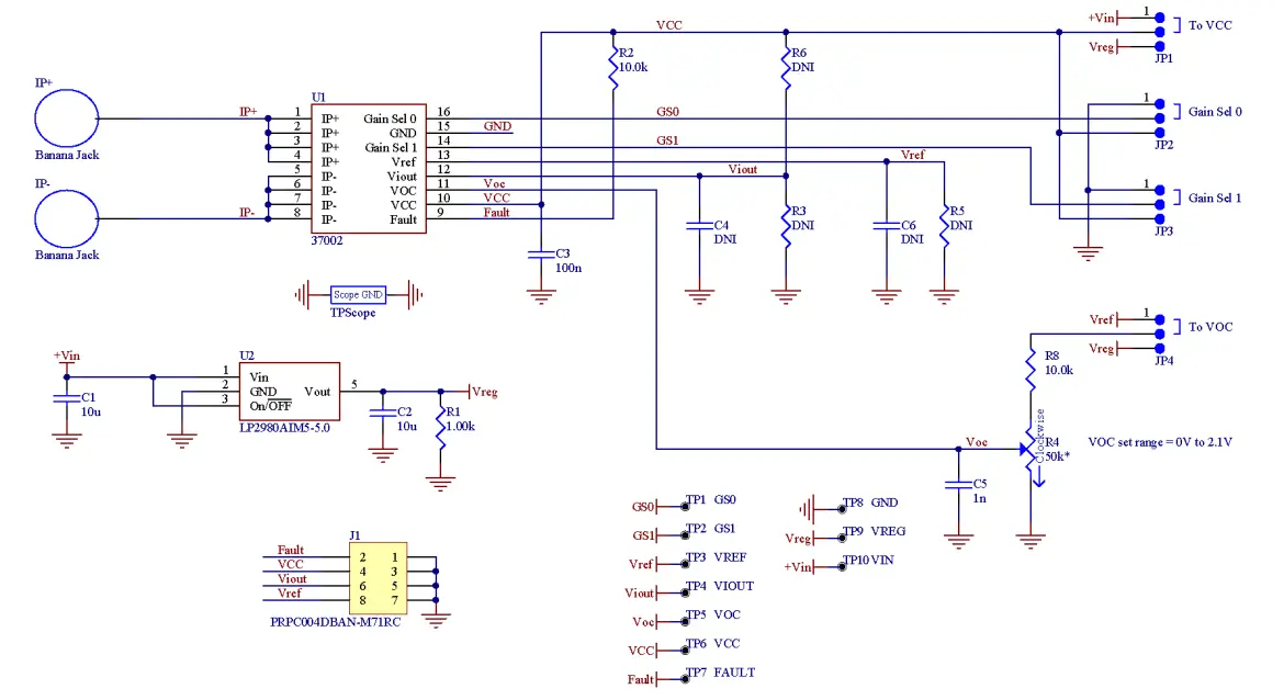
Figure 2: ASEK37002 Schematic
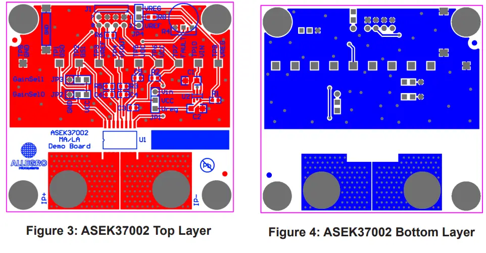
LAYOUT
The ASEK37002 demo board consists of two layers. Top and bottom layers are shown in Figure 3 and Figure 4, respectively.
Bill of Materials
Table 2: ASEK37002 Bill of Materials
| Reference Designator | Description |
| U1 | ACS37002 |
| U2 | IC, LP2980AIM5, SOT-23-5, 3.3 V or 5 V regulator depending on ACS37002 version |
| C1, C2 | Capacitor, 1206, X5R, 50 V, 10 µF |
| C3 | Capacitor, 0603, X7R, 50 V, 100 nF |
| C5 | Capacitor, 0603, C0G, 50 V, 1 nF |
| R1 | Resistor, 0603, 1 kΩ |
| R2 | Resistor, 0603, 10 kΩ |
| R4 | Potentiometer, 50 kΩ |
| R5 | Do Not Install |
| C4, R3, R6 | Do Not Install |
| IP+, IP- | Banana jack |
| JP1, JP2, JP3, JP4 | 3 pin jumper to be used with 2-pin shunts |
| TPFLT, TPGND, TPGS0, TPGS1, TPIn, TPVCC, TPVin, TPViout, TPVOC, TPVref, TPVreg | Test points |
| TPScope | 18ga wire jumper used as connection to PCB ground |
RELATED LINKS
The ACS37002 product datasheet is available for download on the Allegro website. In addition, several application notes and related information is available. This information is listed in the table below.
Table 3: Related Documentation and Application Notes
| Documentation | Summary | Location |
| ACS37002 | Product datasheet defining common electrical characteristics and performance characteristics | https://www.allegromicro.com/-/media/files/ datasheets/acs37002-datasheet.ashx |
| ACS37002 Purchasing | Purchasing homepage | https://www.allegromicro.com/en/products/ sense/current-sensor-ics/zero-to-fifty-amp- integrated-conductor-sensor-ics/acs37002 |
| An Effective Method for Characterizing System Bandwidth in Complex Current Sensor Applications | Application note describing methods used by Allegro to measure and quantify system bandwidth | https://allegromicro.com/en/insights-and- innovations/technical-documents/hall-effect- sensor-ic-publications/an-effective-method-for- characterizing-system-bandwidth-an296169 |
| DC and Transient Current Capability/Fuse Characteristics of Surface Mount Current Sensor ICs | DC and Transient Current Capability/Fuse Characteristics of Surface Mount Current Sensor ICs | https://www.allegromicro.com/en/Insights-and- Innovations/Technical-Documents/Hall-Effect- Sensor-IC-Publications/DC-and-Transient- Current-Capability-Fuse-Characteristics.aspx |
| ACS37002 Gerber Files | Schematic files containing demo board layers | https://www.allegromicro.com/-/media/allegro/ allegromicro/files/gerber-files/asek37002_ gerber_files.ashx |
| High-Current Measurement with Allegro Current Sensor IC and Ferromagnetic Core: Impact of Eddy Currents | Application note focusing on the effects of alternating current on current measurement | https://allegromicro.com/en/insights-and- innovations/technical-documents/hall-effect- sensor-ic-publications/an296162_a1367_ current-sensor-eddy-current-core |
| Secrets of Measuring Currents Above 50 Amps | Application note regarding current measurement greater than 50 A | https://allegromicro.com/en/insights-and- innovations/technical-documents/hall-effect- sensor-ic-publications/an296141-secrets-of- measuring-currents-above-50-amps |
| Allegro Hall-Effect Sensor ICs | Application note describing Hall-effect principles | https://allegromicro.com/en/insights-and- innovations/technical-documents/hall-effect- sensor-ic-publications/allegro-hall-effect-sensor- ics |
| Hall-Effect Current Sensing in Electric and Hybrid Vehicles | Application note providing a greater understanding of hybrid electric vehicles and the contribution of Hall-effect sensing technology | https://allegromicro.com/en/insights-and- innovations/technical-documents/hall-effect- sensor-ic-publications/hall-effect-current- sensing-in-electric-and-hybrid-vehicles |
| Hall-Effect Current Sensing in Hybrid Electric Vehicle (HEV) Applications | Application note providing a greater understanding of hybrid electric vehicles and the contribution of Hall-effect sensing technology | https://allegromicro.com/en/insights- and-innovations/technical-documents/ hall-effect-sensor-ic-publications/hall-effect- current-sensing-in-hybrid-electric-vehicle-hev- applications |
| Achieving Closed-Loop Accuracy in Open-Loop Current Sensors | Application note regarding current sensor IC solutions that achieve near closed-loop accuracy using open-loop topology | https://allegromicro.com/en/insights-and- innovations/technical-documents/hall-effect- sensor-ic-publications/achieving-closed-loop- accuracy-in-open-loop-current-sensors |
| Allegro Current Sensor ICs Can Take the Heat! Unique Packaging Options for Every Thermal Budget | Application note regarding current sensors and package selection based on thermal capabilities | https://allegromicro.com/-/media/allegro/ allegromicro/files/application-notes/an296190- current-sensor-thermals.ashx |
Revision History
| Number | Date | Description |
| – | June 25, 2020 | Initial Release |
| 1 | August 31, 2020 | Updated links in Table 2 |
| 2 | December 11, 2020 | Updated Table 2 |
| 3 | April 21, 2022 | Updated Figure 1-4; minor editorial updates |
| 4 | April 18, 2023 | Minor editorial updates |
Copyright 2023, Allegro MicroSystems.
The information contained in this document does not constitute any representation, warranty, assurance, guaranty, or inducement by Allegro to the customer with respect to the subject matter of this document. The information being provided does not guarantee that a process based on this information will be reliable, or that Allegro has explored all of the possible failure modes. It is the customer’s responsibility to do sufficient qualification testing of the final product to ensure that it is reliable and meets all design requirements.
Copies of this document are considered uncontrolled documents.
For the latest version of this document, visit our website:
www.allegromicro.com
![]() Allegro Micro Systems
Allegro Micro Systems
955 Perimeter Road
Manchester, NH 03103-3353 U.S.A.
www.allegromicro.com
References
 Allegro MicroSystems | Innovation with Purpose
-
Open-Close-Loop-Accuracy-ACS720
-
Hall-Effect Sensors | Allegro MicroSystems
-
System Bandwidth in Complex Current Sensor Applications
-
Secrets of Measuring Currents Above 50 Amps
-
High-Current Measurement with Allegro Current Sensor
-
Hall Effect Current Sensing in Electric and Hybrid Vehicles
-
Hall Effect Current Sensing in Hybrid Electric Vehicle (HEV) Applications
-
allegromicro.com/-/media/files/datasheets/acs37002-datasheet.ashx
-
DC and Transient Current Capability/Fuse Characteristics of Surface Mount Current Sensor ICs
-
Semiconductors | Products | Allegro MicroSystems
-
ACS37002: 400 kHz, High Accuracy Current Sensor


