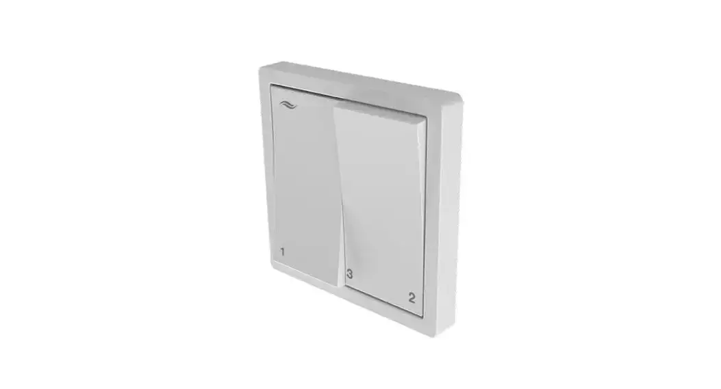
![]() Pure Ventilation control unit
Pure Ventilation control unit
Instruction Manual
Pure Ventilation control unit
Trademarks, copyrights, and property rights
inventor® is a registered trademark of inventor GmbH.
The copyright to this document remains with the manufacturer.
Rights to all content and images: © inventor GmbH 2022.
All trademarks used in this document are the property of their respective manufacturers and are hereby acknowledged.
Disclaimer
This documentation represents a translation of the original german operating instructions. The information on access to the operating instructions must be passed on to third parties when the system is handed over.
The content of this documentation has been checked for compliance with the described components. Nevertheless, deviations may still occur, therefore no guarantee of compliance can be provided.
This documentation describes the functionality of the standard scope.
For reasons of clarity, the documentation does not purport to cover all details on all types of products and cannot cover every conceivable scenario for commissioning, operation, cleaning, and care.
The illustrations in this document may differ slightly from the design of the product that you have purchased. The same functionality is ensured despite any design deviations.
This documentation is updated regularly. Necessary corrections and appropriate supplements are always included in subsequent editions. You can find the latest version at
www.inventer.de/downloads.
Company information
Publisher:
inventor GmbH
Ortsstraße 4a
07751 Löberschütz
Germany
Phone: +49 (0) 36427 211-0
Fax: +49 (0) 36427 211-113
E-mail: [email protected]
Web: www.inventer.de
CEO: Annett Wettig
VAT ID number: DE 815494982
Jena District Court HRB 510380
User and safety instructions
Thank you for purchasing this high-quality product from the inventor!
This section provides an overview of the basic safety precautions for the safe and proper operation of your control unit.
1.1 User information
Safety and warning instructions
The safety and warning instructions in these operating instructions have a uniform structure and are marked with a symbol on the left side of the instruction. A signal word in front of the text also indicates the hazard level. If several hazard levels exist, the highest level of safety instruction is always used.
The safety and warning instructions contain the following information:![]() SIGNAL WORD: Type and origin of the danger. Possible consequences of the danger! Measures to avoid the danger.
SIGNAL WORD: Type and origin of the danger. Possible consequences of the danger! Measures to avoid the danger.
The signal word indicates the severity of the potential danger unless preventive measures are taken:![]() WARNING means Possible danger of serious injury or death.
WARNING means Possible danger of serious injury or death.![]() CAUTION means Direct danger of minor/significant injury.
CAUTION means Direct danger of minor/significant injury.![]() NOTICE means: Direct or possible risk of property damage due to an adverse event/state.
NOTICE means: Direct or possible risk of property damage due to an adverse event/state.
If you see these signs, ensure you observe the described measures to prevent possible hazards and/or damage.
Other symbols used in this documentation
In addition to the safety instructions, the following symbols are used:![]() A TIP symbol indicates practical and useful tips for handling your control unit.
A TIP symbol indicates practical and useful tips for handling your control unit.![]() All illustrations show the interior wall.
All illustrations show the interior wall.
► Action required: This prompts the user to perform a specific action.
⇒ Check the results requires you to check the results of the action you have performed.![]() Action focus: To be taken into account in the corresponding step.
Action focus: To be taken into account in the corresponding step.
1.2 Safety instructions
The operating instructions are part of your Pure control unit and must be available at all times (see www.inventer.de/downloads). When handing the system to a third party, the information regarding access to the operating instructions must be handed over also.
Before performing any work on the equipment/system, read the operating instructions carefully and observe all notices in this section.
Also, note the safety instructions that precede the described handling instructions. Non-observance of safety instructions could result in injury and/or property damage.
Intended use
The Pure control unit (also referred to in the further text as “controller” or “Pure controller”) must only be used to control decentralized iV ventilation units with heat recovery from inventor GmbH.
Specifically, the following must be used:
- The Pure controller for controlling the inventor ventilation units with heat recovery integrated into the system.
- The sensor technology paired with the controller (HYG18 humidistat, HYG12 humidistat, CS1 CO2 sensor, or pressure monitor) for the delivery of temperature, humidity, and CO2 values to the Pure controller, which in turn uses these values to control the inventor ventilation units with heat recovery.
Requirements for intended use
- Use the units integrated into the ventilation system only in accordance with the applications that are described in this documentation and only in conjunction with the components that are recommended, approved, and named by inventor GmbH in this documentation.
Changes or modifications to the units are not permitted. - Your ventilation system is exclusively designed for use in ambient temperatures between -20 and 50°C.
- Proper operation and maintenance are required for the trouble-free and safe operation of the equipment/system.
- These operating instructions are only valid in conjunction with the installation instructions of the corresponding ventilation unit with heat recovery and supplement these.
All legal notices that are listed in the respective operating instructions also apply without restriction to this document.  CAUTION: The Pure controller must not be operated or cleaned by children and/or persons who are not able to do so safely due to their physical, sensory or mental abilities, inexperience, or lack of knowledge unless they are supervised by a person responsible for their safety or have received instructions from them on how to operate the system. Small children must be supervised to ensure that they do not play with the system’s devices.
 NOTICE: The unit has scratch-sensitive plastic surfaces. Do not touch the components with oily and/or dirty hands. Avoid contact with sharp or pointed objects, e.g. rings.
Any kind of use other than the intended use will exclude all liability claims.
Improper use
The Pure controller is intended exclusively for the control of the ventilation units specified in the section on the intended use. Any other use is strictly prohibited.
System overview: Pure controller
The Pure controller is an electronic programming unit for controlling inVENTer® ventilation units with heat recovery. It is available in two versions (standard or flat) with two further variants in each case:
- Pure p4 controller with an interface for connecting an external sensor;
- Pure p4 Fire controller with an interface for connecting a safety device.
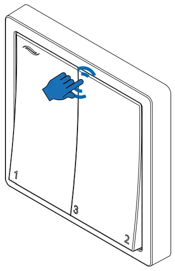
Operation is carried out by setting the rocker switch in various positions.
Integrated indicator lights mean that the switch acts simultaneously as a visual feedback/display for the user.
The Pure controller can be used either as a base control unit or with additional sensors connected.
An external interface allows the scope of functions to be expanded:
- p4: Demand-based ventilation via sensor technology (humidistat, CO2 sensor, VOC sensor¹),
or - p4 Fire: Integration of a safety device (e.g. pressure monitor) with simultaneous operation of the ventilation units with fireplaces.
Components
The Pure controller consists of a control module with connecting terminals that contain the electronics for controlling the connected ventilation units, two status LEDs for visual feedback for the user, as well as a switching power supply unit.
A serial or double switch is used as the operating and display interface.
Versions
The Pure controller is available in the standard and flat versions.
Flat version: The controller switches off the ventilation unit for 1 hour when in “Off” mode. Subsequently, the ventilation unit continues to work in heat recovery mode at ventilation level 1 (25 %).
The use of the Flat version is recommended in areas where it is desirable not to turn off the ventilation system in order to protect against moisture build-up.
Standard version: The Pure controller switches the ventilation unit off completely when in “Off” mode. For the ventilation unit to work again, a ventilation level must be selected.
¹) VOC = volatile organic compounds
2.1 Function
A Pure controller is a control unit for decentralized ventilation units with heat recovery from inventor GmbH. Where these are connected, the information determined at the controller via the sensor technology is incorporated into the control of the ventilation unit.
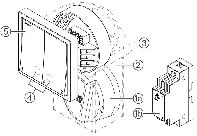
- a Flush-mounted switching power supply unit, or
b DIN rail switching power supply unit - Mounting box
- Control module
- Display LED (RGB LED)
LED red: Heat recovery
LED green: Ventilation - Switch, programming unit
If no sensor is connected (basic control unit), the operating mode and intensity of the airflow can be set on the Pure controller.
Possible operating modes:
- Heat recovery
- Ventilation
- Pause timer
- OFF (p4 and p4 Fire only)
There are three ventilation levels for the ventilation units which define the rotational speed of the fans and therefore the units’ airflow. These are fixed and cannot be changed:
- Ventilation level 1 – 25 %
- Ventilation level 2 – 50 %
- Ventilation level 3 – 100 %
If sensors are connected to the Pure controller, the range of the controller’s functions increases and this also allows demand-based ventilation alongside manual ventilation.
The sensor used must have a potential-free relay contact as its output.
The increase in functions depends on the variant of the controller:
| Controller variant | Sensor | Limit value exceeded | Limit value not reached |
| p4 p4 Flat | CO2 sensor | Switch all ventilation units connected to the controller to ventilation mode, output level 75 %. | Switch all ventilation units connected to the controller to the originally set operating mode and ventilation level. |
| VOC sensor | |||
| Humidistat | |||
| p4 Fire p4 Fire Flat | Pressure sensor (4 Pa) | Switch all ventilation units connected to the controller to OFF mode. |
Operation
3.1 General information
The heat recovery and ventilation operating modes can be changed by moving the left-hand rocker switch back and forth 2 times. The pause operating mode is switched on or off by moving the right-hand rocker switch back and forth 2 times. The ventilation unit can also be switched off completely (standard version only).
There are three ventilation levels for the ventilation units which define the rotational speed of the fans and therefore the intensity of the unit’s airflow.
The ventilation levels are adjusted by changing the switch positions
The display LED (RGB LED)
The display LED is located behind the rocker switches and shows the state of the controller in different colors. The following displays are possible:
| LED color | LED state | Status of the controller | Presentation | |
| RED | Lights up solid | Heat recovery mode is active. | 11 | |
| RED | Flashing | Safety device sensor triggered. | 14 | |
| GREEN | Solid | Ventilation mode is active. | 11 | |
| GREEN | Flashing | Connected external sensor, e.g. humidistat, triggered. | 14 | |
| RED / GREEN | Alternate flashing | Display filter change. | 13 |
The display LED lights up solid for 10 seconds after switching the double switch (of an input). The LED then goes out automatically.
If the LED is flashing, this indicates a state that must be actively resolved by the user or controlled by the sensor technology.
3.2 Setting the ventilation level
The intensity of the ventilation can be set in three stages by changing the switch positions. The ventilation levels are fixed and cannot be changed.
The following ventilation levels are defined:
- Ventilation level 1 – 25 %
- Ventilation level 2 – 50 %
- Ventilation level 3 – 100 %
The new setting takes effect immediately so that adjustments can be made purely by listening to changes in the sound level.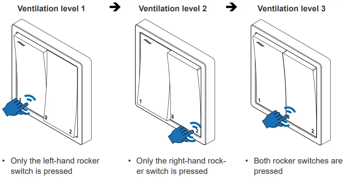
3.3 Switching off the ventilation
In this mode, the reversible fans on the ventilation device are switched off. The ventilation units do not work and there is no exchange of air. In this state, close the inner cover. Select “Off” if your ventilation unit is to remain switched off for a prolonged period, e.g. to clean the ventilation device or when the inner cover is closed.
OFF mode is set by changing the switch positions.
 | Switching off the ventilation unit ► Switch both rocker switches off. ⇒ All of the ventilation units connected to the controller are switched off. Switching the ventilation unit back on ► Select any of the ventilation levels 1 – 3. ⇒ All of the ventilation units connected to the controller restart at the selected ventilation level. |
![]() In individual cases, after the ventilation unit has been switched off for an hour, it restarts in heat recovery operating mode at ventilation level 1. This is not an error, but rather the flat version of the Pure controller.
In individual cases, after the ventilation unit has been switched off for an hour, it restarts in heat recovery operating mode at ventilation level 1. This is not an error, but rather the flat version of the Pure controller.
Complete switch-off of the ventilation unit is only possible with the standard version of the Pure controller.
3.4 Setting heat recovery/ventilation mode
The heat recovery and ventilation operating modes can be changed by moving the left-hand rocker switch back and forth 2 times.
The starting position of the rocker switches is not relevant here.
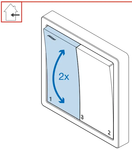 | ► Switch the left-hand rocker switch back and forth twice from its current position. ⇒ The operating mode is set/changed. ⇒ The display LED lights up.
► Select the ventilation level at which the ventilation unit is to operate. | |||||||||
![]() Heat recovery mode
Heat recovery mode ![]()
In this operating mode, the reversible fans of the ventilation units operated in pairs change their direction of rotation every 70 seconds. The integrated thermal accumulator charges itself with the heat energy from the room’s warm air as it flows to the outside (extract air). When the fan changes direction, it releases the stored heat energy into the incoming outdoor air (supply air).
Select “Heat recovery” as the default operating mode. During the heating periods, the outdoor temperature is cooler than the temperature of the air inside. The outdoor air flowing in is pre-warmed by being fed over the ceramic thermal accumulator before making its way indoors. On summer days, this is also recommended. The higher outdoor temperature compared to the indoor temperature means that the supply of heat is significantly reduced during ventilation.![]() Ventilation mode
Ventilation mode ![]()
In this mode, the reversible fans do not change their direction of rotation. This means that no heat recovery takes place.
Select “Ventilation” to cool the room on summer nights, or to quickly remove stale or humid indoor air.
3.5 Activating / deactivating the pause timer
With the pause timer, the ventilation unit’s reversible fans are switched off for 1 hour. This period is pre-set and cannot be changed.
The pause timer can be activated by switching the right-hand rocker switch back and forth twice.
The starting position of the rocker switches is not relevant here.
If the pause timer is active, it can be interrupted/deactivated at any time by switching the righthand rocker switch back and forth twice.
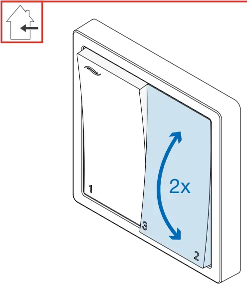 | ► Switch the right-hand rocker switch back and forth twice from its current position. All switching operations must be carried out within around 2 seconds (switch back and forth quickly). ⇒ The pause timer is activated/deactivated.
► Select the ventilation level at which the ventilation unit is to operate after the pause. |
![]() Pause timer
Pause timer
The reversible fans on the ventilation unit are temporarily switched off (for 1 hour). The ventilation units do not work and there is no exchange of air.
Following the temporary pause, the fans restart independently at the selected ventilation level and in the pre-set operating mode.
You should therefore leave the inner cover open.
Select the pause timer if your ventilation unit is to be temporarily switched off, for example before going to sleep.
3.6 Acknowledging a filter change
After 180 days (approx. 6 months), the required filter change is indicated by alternate flashing of the red and green LED.
Once the filter has been changed, this must be confirmed on the controller.
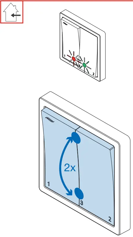 | Requirements: • The red and green LEDs are flashing alternately. ► Change the filters on the ventilation units (see the operating instructions for your particular ventilation unit). To do this, pause the ventilation unit. ► Move both rocker switches to the same position (OFF or ventilation level 3). ► Simultaneously switch both rocker switches back and forth twice from their current position. ⇒ Both LEDs go out. ⇒ The LED to indicate the current operating mode lights up solid for 10 seconds. ⇒ The filter change interval is reset to 180 days. ► Select the ventilation level at which the ventilation unit is to operate. |
3.7 Sensor technology activated
Depending on the sensor connected, the ventilation unit’s range of functions increases.
The triggering of a sensor is indicated by flashing the red (safety device) or green (external sensor) LED, and this cannot be switched off manually.
Connecting an external switching contact (p4 / p4 Flat versions)
If the pre-defined limit on the external sensor, e.g. CO2 sensor or humidistat, (which cannot be changed on the controller) is exceeded, the sensor relays this to the controller:
 The green LED on the Pure controller flashes.
- The controller switches all connected ventilation units to ventilation mode with a pre-defined air flow of 75%.
![]() Ventilation with an airflow of 75 % cannot be selected manually as it is only enabled when the sensor technology is triggered.
Ventilation with an airflow of 75 % cannot be selected manually as it is only enabled when the sensor technology is triggered.
The function remains active until the corresponding limit value falls below the pre-set limit value again:
 The green LED on the Pure controller goes out.
- All of the ventilation units connected to the controller restart in the original set operating mode and ventilation level.
Integrating a safety device (p4 Fire / p4 Fire Flat versions)
The external interface is used to integrate safety devices, e.g. a 4 Pa pressure sensor, into the ventilation system while simultaneously operating the ventilation system with fireplaces.![]() WARNING: For joint operations with fireplaces, safety measures must be taken to prevent negative pressure from developing in the building.
WARNING: For joint operations with fireplaces, safety measures must be taken to prevent negative pressure from developing in the building.
- The responsible chimney sweep and/or building planner decides which measures need to be carried out.
If this interface is used in conjunction with an external pressure sensor (4 Pa pressure sensor), the air pressure indoors is continuously monitored. As soon as this exceeds the safety-relevant limit, the sensor transmits this to the controller.
 The red LED on the Pure controller flashes.
- The controller switches all connected ventilation units off immediately
The function remains active until the corresponding limit value falls below the safety-relevant limit value again:
 The red LED on the Pure controller goes out.
- All of the ventilation units connected to the controller restart in the original set operating mode and ventilation level.
Cleaning and care
![]() CAUTION
CAUTION
Cleaning by children and persons with limited abilities.
Injury to persons and/or incorrect functioning of the ventilation system!
- No cleaning or maintenance activities may be performed on the ventilation system by children and/or persons who are not fully capable of safely doing so due to their physical, sensory, or mental capabilities, inexperience, or lack of knowledge.
The Pure p4 controller is virtually maintenance-free. Any servicing work required can be carried out by the user after brief instructions.![]() TIP:
TIP:
Disconnect the power supply for any cleaning or care work.
Detergents![]() NOTICE
NOTICE
Due to the controller’s scratch-sensitive plastic surface, damage may occur to the surface.
- To prevent damage to the surface, do not use sand, soda, acid, or chlorine-based cleaning agents.
A commercially available detergent in warm water can be used for cleaning.
The following tools may be used for cleaning:
- lint-free, soft cloth
- soft brush
Service recommendations
The servicing tasks and intervals listed here are recommended by inventor GmbH to maintain the functionality and performance of your controller.
Depending on requirements, your personal schedule may deviate from these recommendations.
| Interval | Module | Maintenance activity |
| Monthly | Pure controller | Clean the rocker switches and frame with a damp cloth. |
Accessories and spare parts
Contact your local distributor to order accessories for your ventilation system.
| Component | Item number |
| Programming unit | |
| Pure p4 controller series switch | 1004-0210 |
| Control module incl. LEDs1) | 2008-0013 (p4) |
| 2008-0015 (p4 Flat) | |
| 2008-0016 (p4 Fire) | |
| 2008-0017 (p4 Fire Flat) | |
| Sensor technology (optional) | |
| CO2 sensor CS1 | 1004-0145 |
| HYG18 humidistat | 1002-0044 |
| HYG12 humidistat | 1002-0015 |
| Switching power supply units | |
| Switching power supply unit NT17-s8 (for DIN rail installation) | 3002-0275 |
| Flush-mounted switching power supply unit NT17-Mz/s8 | 3002-0267 |
¹) The controller version required can be found on the control module’s type plate.
Troubleshooting and disposal
Troubleshooting
| Fault | Possible cause | Remedy |
| Control module not working | Pause timer set. | Cancel the pause timer: move the right-hand rocker switch back and forth twice. |
| LEDs do not light up/show the wrong operating mode. | Connection not correct/incorrect polarity. | Check the power supply. Check connection/contacts. |
| The control elements do not operate as described. | Connecting wires to the switch back to front. | Check the brown/white wires on the switch. |
| LED flashing red. Fans are not running. | External switching contact triggered. | Check the sensor/pressure sensor. Check the controller variant (information on type plate): p4 (Flat): Sensor p4 Fire (Flat): Pressure Monitor |
| LED flashing green. Fans at output level 75 %. | ||
| LED flashes alternately red and green. | Indicator for filter change | Clean/replace the filter. |
If you cannot eliminate the fault, please contact our technical customer service.
You can find information about doing so in section 11: Service.
Dismantling and disposal
Dismantle the controller before disposal.![]() Your Pure controller contains valuable materials that can be recovered and recycled. The separation of waste materials into different varieties facilitates recovery of the recyclable materials. Contact an electronic appliance disposal company to arrange environmentally friendly recycling and disposal of your old system. They will dispose of the product in compliance with the applicable national regulations. Ensure that the product’s packaging is sorted correctly for disposal.
Your Pure controller contains valuable materials that can be recovered and recycled. The separation of waste materials into different varieties facilitates recovery of the recyclable materials. Contact an electronic appliance disposal company to arrange environmentally friendly recycling and disposal of your old system. They will dispose of the product in compliance with the applicable national regulations. Ensure that the product’s packaging is sorted correctly for disposal.
The table below contains disposal recommendations.
| Product | Material | Disposal |
| Switch guard | Plastic recycling | |
| Pure control module | Electronics | The collection point for electrical appliances |
| Switching power supply unit |
Guarantee and warranty
Guarantee
Outside Germany, the national guarantee provisions of the country in which the system is sold apply. Please contact the distributor for your country.
The guarantee covers all defects that were present at the time of purchase. Failure to observe the intended use will invalidate all warranty claims.
Manufacturer Warranty
inventor GmbH provides a five-year warranty for electronic components. This covers premature product wear.
Further information about the warranty is available at www.inventer.de/garantie
Service
Claims
Check the delivery for completeness and transport damage upon receipt using the delivery note.
Report missing items immediately, and at the latest within 14 days to your supplier, distributor, or factory representative.
Warranty and guarantee claims
In the case of a warranty or guarantee claim, contact your local distributor or factory representative.
In all cases, please return the complete unit to the manufacturer.
The warranty is an additional offering by the manufacturer and in no way affects the applicable law.
Accessories and spare parts
To order components for your ventilation unit, contact your nearest distributor or our service staff.
Technical customer service
For technical support contact our service staff:![]() +49 (0) 36427 211-0
+49 (0) 36427 211-0![]() +49 (0) 36427 211-113
+49 (0) 36427 211-113![]() [email protected]
[email protected]![]() http://www.inventer.de
http://www.inventer.de
![]() inventor GmbH
inventor GmbH
Ortsstraße 4a
07751 Löberschütz
Germany
www.inventer.de
Subject to modifications.
We accept no liability for printing errors.
Item number: 5021-0021
Version: 1.0 – 02/2022![]()
References
 inVENTer-Downloads: Alles zu Ihren inVENTer-Produkten
-
inVENTer-Herstellergarantie - Vertrauen Sie auf Qualität
-
inVENTer-Herstellergarantie - Vertrauen Sie auf Qualität
-
Decentralized ventilation systems - invisible, energy-efficient, silent
-
Decentralized ventilation systems - invisible, energy-efficient, silent


