RCT power Storage DC 4.0 Photovoltaic and Battery Inverter
Power Storage DC 4.0 / 6.0
This setup manual contains a short instruction required for installing, wiring, commissioning and operating the inverters. For further instructions on installing or operating, please refer to the detailed user manual, which you can access via www.rct-power.com .
RCT Power GmbH reserves the right to make changes to specifications or documents without prior notice. RCT Power GmbH shall not be responsible for any damages resulting from use of this document. This document does not replace any applicable laws, regulations, standards or codes.
Warranty conditions come enclosed with the device. No warranties can be derived from this document.
Symbols Explanation
| Symbols Explanation
| Level of risk | ||
| high | medium | low | |
| Immediate of death & or serious injurie |
|
| |
| Immediate & danger of minor or moderate injury |
| ||
| Danger of equipment or property damage |
| ||
Intended Product Usage
 WARNING
To prevent personal injury or property ! damage, the inverter must only be installed, wired, connected, commissioned, maintained and serviced by qualified personnel:
- Trained in installing electrical devices.
- Familiar with all applicable laws, regulations, standards and codes for electrical devices.
- Familiar with safety requirements and safety-related guidelines for electrical devices.
- Familiar with work protection laws and regulations. Using the appropriate personal protective equipment.
Power Storage DC 4.0, 5.0 and 6.0 are stationary 3-phase string inverters with integrated battery charger. They convert direct current IDC) supplied by the PV array and the battery into alternating current [AC). which can be fed into the electricity grid.
They are not designed for any other application or connection to other devices.
Any use that differs from or goes beyond the intended usage is considered misuse. RCT Power GmbH shall not be liable for any damage resulting from misuse.
Any misuse will terminate warranty, guarantee and general liability of the manufacturer.
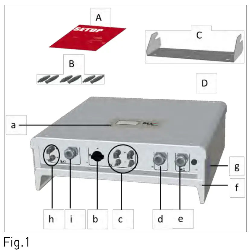
Scope of Delivery
| Item | Description |
| A | Setup manual |
| B | PV input- and battery connectors [Weidmuller PV-Stick] |
| C | Wall bracket |
| D | Inverter |
| a | LCD display for information on inverter operation |
| b | DC switch |
| c | DC PV plugs |
| d | Cable entries for communication ports |
| e | Cable entry for AC cable |
| f | Screw hole for additional protective grounding |
| g | Name plate with technical data, serial number, symbols |
| h | DC battery plugs |
| i | Cable entries for RJ45 connectors: Battery, Power Sensors and Power Switch |
 Look over user manual.
 Hot surface
 Wait 10 minutes after disconnection before touching inner parts.
CAUTION Electrical device: grounding necessary
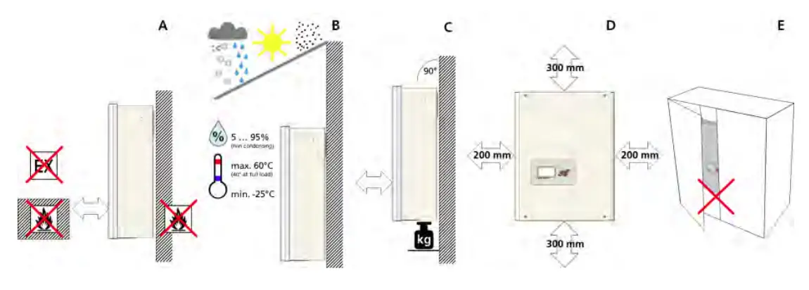
Inverter Mounting
| Item | Description |
| A | Select non-flammable, firm wall. Room may not contain highly flammable goods, liquids or gas. |
| B | Protect from snow, rain, direct sunlight and dust. Observe allowed ambient temperature [-25 … 60°C]. Maximum degree of pollution PD2. |
| C | Mount in upright position. Ensure enough space for easy access. Make sure wall supports inverter weight. |
| D | Minimum clearance: half of inverter width at both sides and half of height at top and bottom. |
| E | Do not place inverter in closed cabinet. |
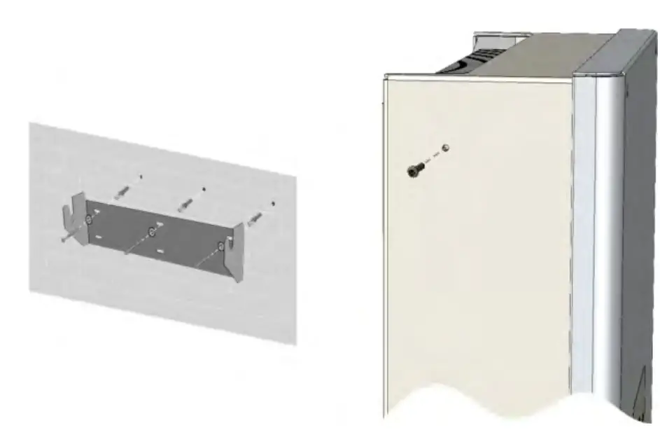
| Item | Description |
| 1 | Attach wall bracket firmly to wall with 3 to 6 screws [0 6 to 8 mm], matching wall plugs and washers [outer 0 min. 18 mm]. Material not included in delivery. |
| 2 | Take out locking screw of inverter at the top left and right sides. Hook inverter onto wall bracket and fix locking screw back. |
Electrical Connection
DANGER
Risk of death or injury due to electric shock! While the inverter is connected to grid [AC voltage source]. to PY array which is exposed to sunlight [DC voltage source] or to the battery [DC voltage source]. high voltage is present in cables and inner parts of inverter.
- Important: ALL voltage sources (DC/ PY-generator, DC / battery and AC/ utility grid) must be disabled before any electrical work.
To disable PY-generator DC voltage connection turn DC switch to 0-position and wait 10 minutes before continuing.
To disable AC voltage connection turn off AC switch, main breaker or fuse. Make sure, other persons don’t switch back. - Do not enable voltage connections until work is finished. To disable DC battery voltage connection both voltage sources (DC/ PY-generator and AC/ utility grid) must be disabled.
- During AC connection: Do not exchange L, N and PE wires!
- Make sure other persons keep away during electrical work.
WARNING
Risk of death or injury due to electric arc!
Disconnecting DC plugs under load can cause electric arcs.
![]() NOTICE
NOTICE
Risk of damage due to improper installation and operation or misuse.
- Contact Local utility company or grid operator before connecting inverter to grid.
- Provide for an AC disconnection device [typical miniature circuit breaker 3 pole 6kA, B-characteristic 16A].
- If required in country or installation, install a residual-current device [RCD]. or residual current circuit breaker [RCCB].
- Inverter contains no owner serviceable parts. Contact Local authorized personnel for service.
- Do not remove name plate.
- Only RCT Power certified batteries complying with the demands of the certain region are allowed to be used.
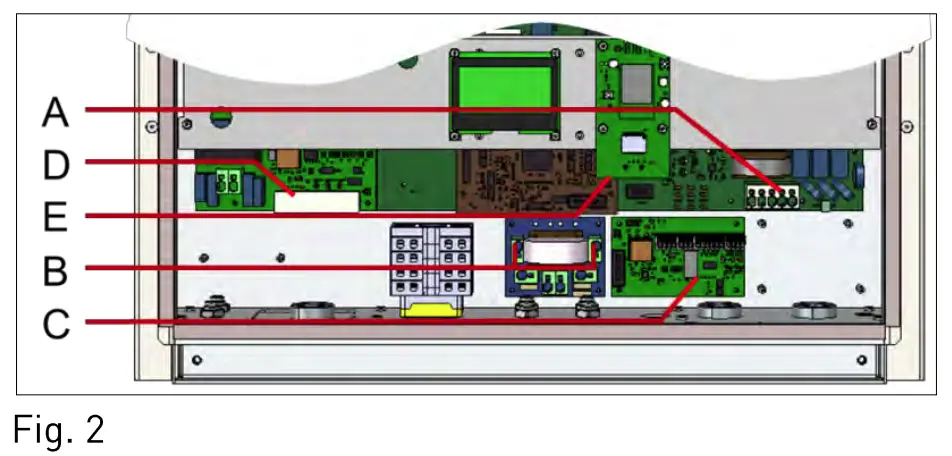
Overview Connection Parts
| Item | Description |
| A | AC terminal block for L 1, L2, L3, N and PE phases. |
| B | Clamps for parallel DC mode. |
| C | Communication board. |
| D | RJ45 Connectors for Battery, Power Sensor and Power Switch. |
| E | RJ45 socket for connection of the Ethernet interface. |
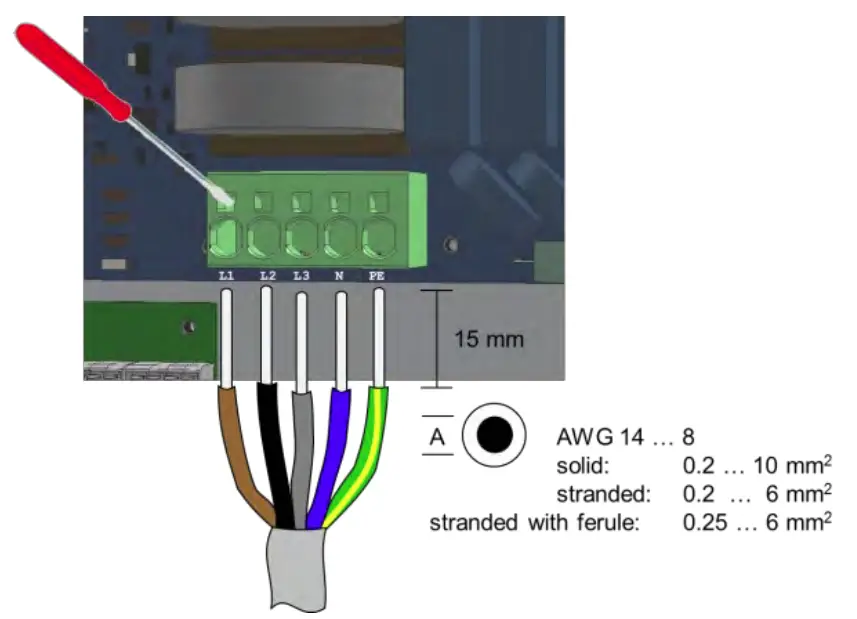
AC Connection
| Item | Description |
| 1 | Remove cover of inverter. Locate AC terminal block [Fig. 2, Al. |
| 2 | Feed cable through AC entry [Fig. 1, el. Push down clamps to insert L 1, L2, L3, N and PE . |
| 3 | Tighten swivel nut of cable entry. |
DC Connection
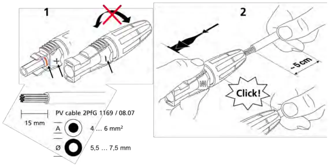
| Item | Description |
| 1 | Do not turn plug parts before inserting the cable. Select correct plugs for polarity of PV and battery strings. |
| 2 | Push cable into plugs straight until the spring clamp locks. |
| 3 | Turn lower part of plug shut. |
| 4 | Make sure DC switch is “0”. Plug corresponding plus and minus poles into adjacent PV plugs of inverter [Fig. 1, cl. |
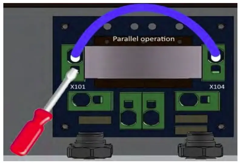
DC Parallel Mode
This section applies only, if several Strings with an equal amount of modules are to be connected in parallel and the maximum input current per input therefore exceeds 12A.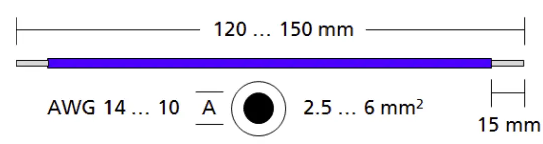
WARNING
To prevent personal injury or property damage, make sure that there is no PV-DC connector plugged and DC switch is “0” in during this installation.
| Item | Description |
| 1 | Remove cover of inverter. |
| 2 | Connect clamps X101 and X104. [Show Fig. 2, Bl. |
DC Battery Connection
Make sure the DC switch of the inverter is set to “0”, the battery ON/OFF switch set to “0” and AC through the main breaker or fuse is disconnected.
Plug the battery connectors to the inverter.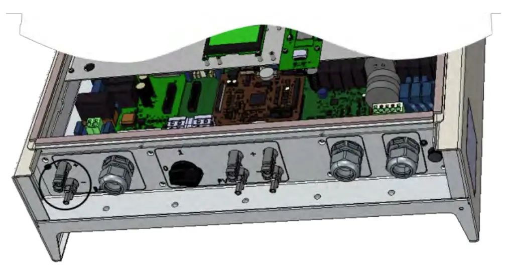
(The connection cables from the inverter to the battery is not included].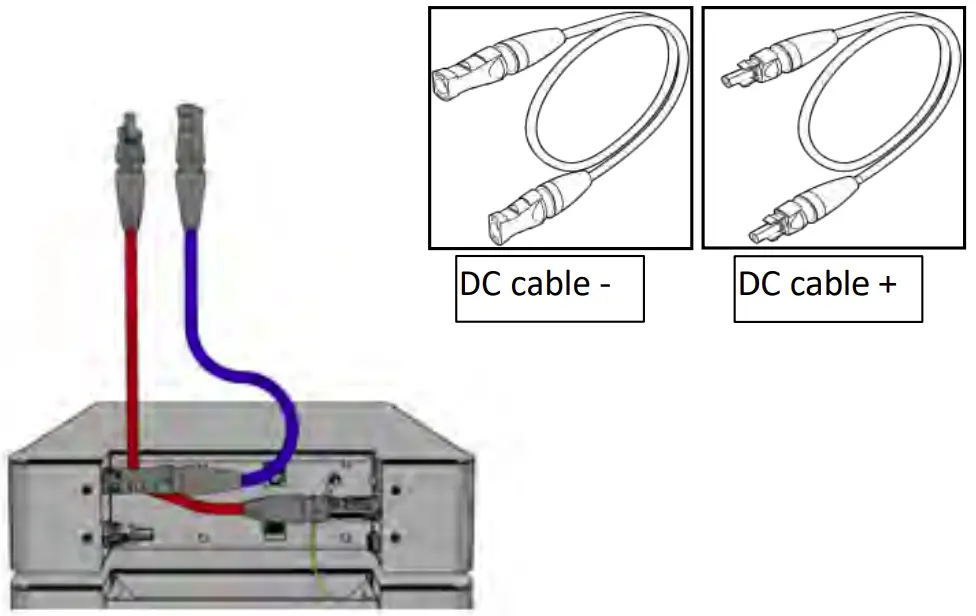
Second Protective Inverter Grounding
If required in the country of installation, attach a second protective earth connection to the housing.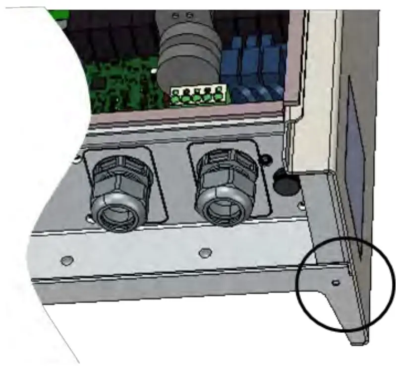
Material not included in delivery.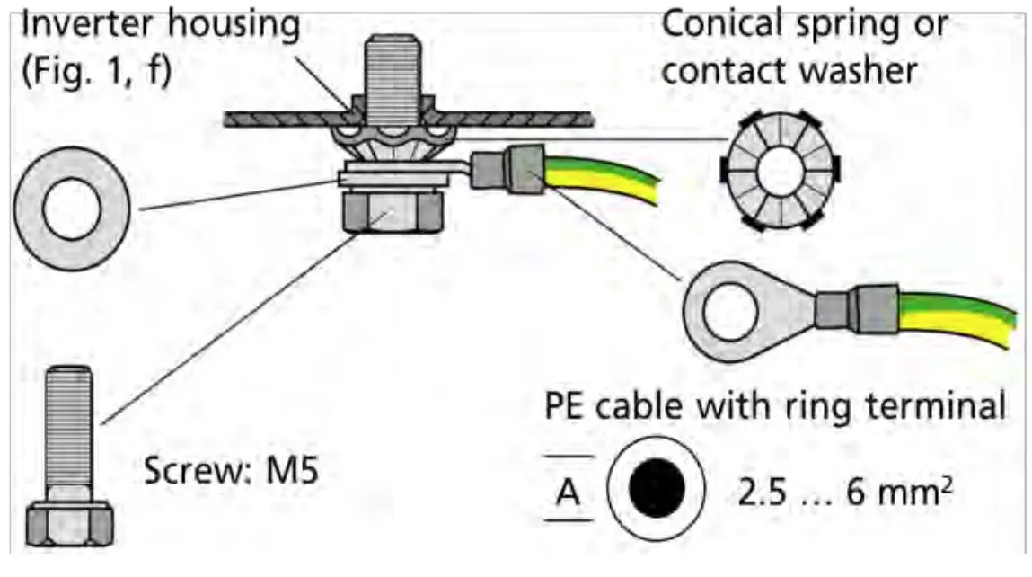
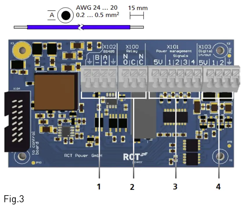
1/0-Board Communication Connection
| Item | Description |
| 1 | X102: serial RS485 interface. |
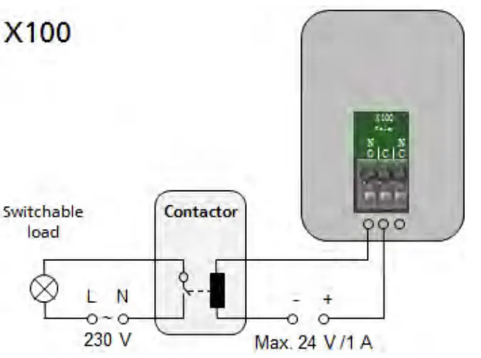
| 2 | X100: Multifunctional Relay, max. 24 V,1A. |
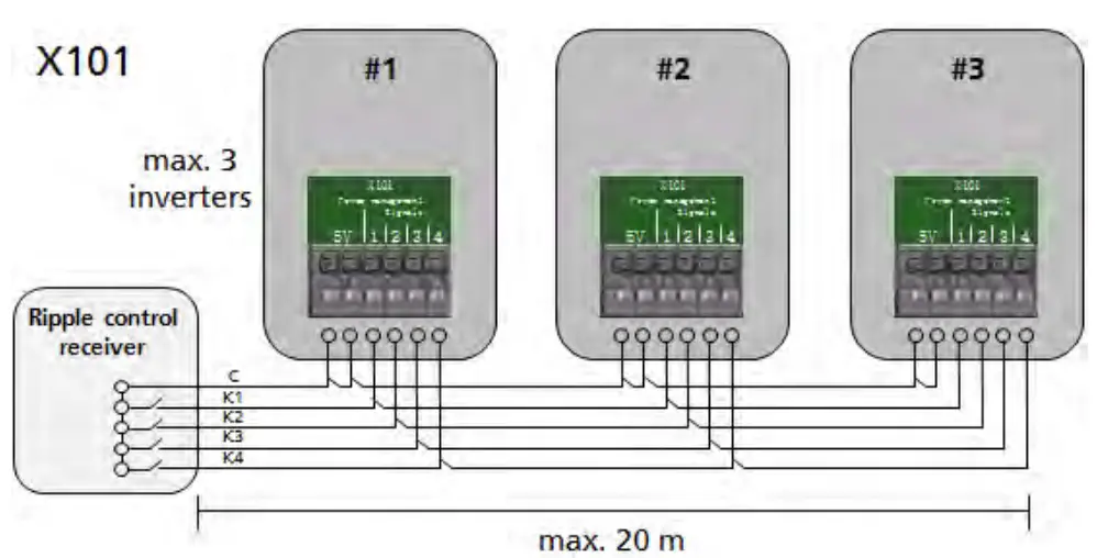
| 3 | X101, Power management: 4 digital inputs for potential free relay contacts. |
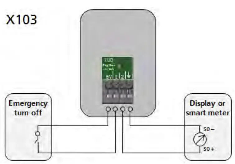
| 4 | X103: Digital in/out [SO-signals], max. Input 24 max output 5V 10 mA |
Connection of Communication Ports
| Item | Description |
| 1 | Use the feed cables for the corresponding cable entry [Fig. 1, d]. |
| 2 | Select correct port [see next section], press down spring clamp, insert cables and release. |
Wiring of Communication Ports
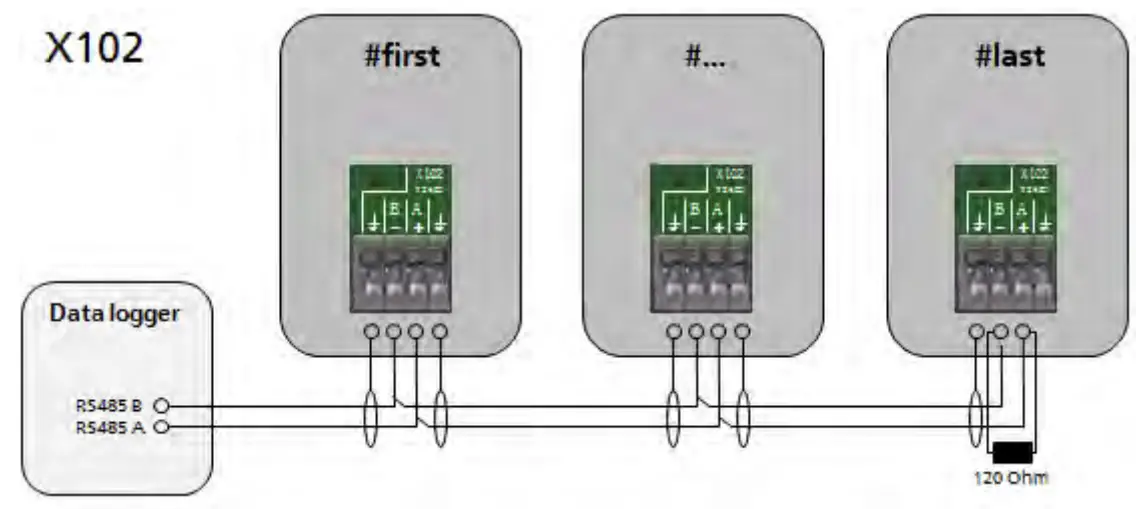
RJ45 Connectors for Power Battery, Power Sensor and Power Switch communication
The inverter communicates with the battery via the CAN-Bus.
If the inverter is delivered with an optional Power Sensor or Power Switch please refer to user manual of these items for further detailed commissioning information.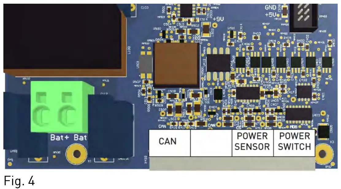
RJ45 – Communication Ports
Description
CAN:
Battery communication connector.
Power Sensor:
Current sensor communication connector.
Power Switch:
Power Switch communication connector.
Connection of RJ45 – Communication Ports
| Item | Description |
| 1 | Open cable entry [Fig. 1, i] and feed cables. |
| 2 | Select correct port [see Fig. 4 and next section]. insert cables in RJ45 connectors. |
Wiring of RJ45 – Communication Ports
Standard communication with Power Battery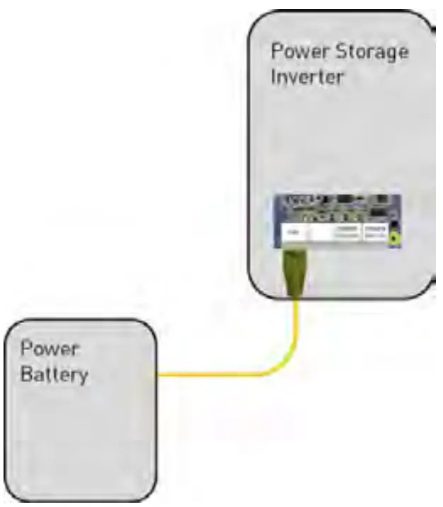
Additional Power Switch communication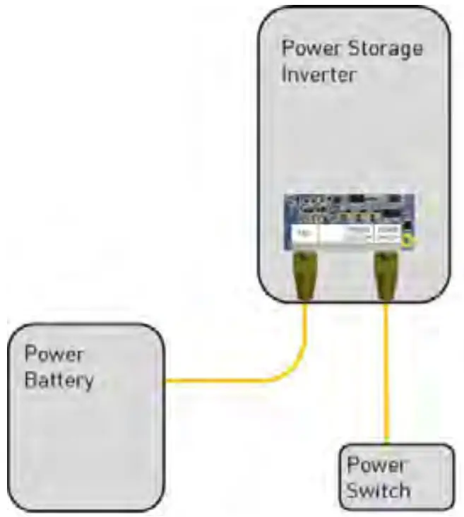
Additional Power Sensor communication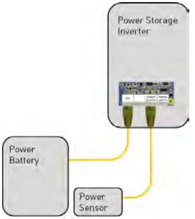
Additional Power Switch and Power Sensor communication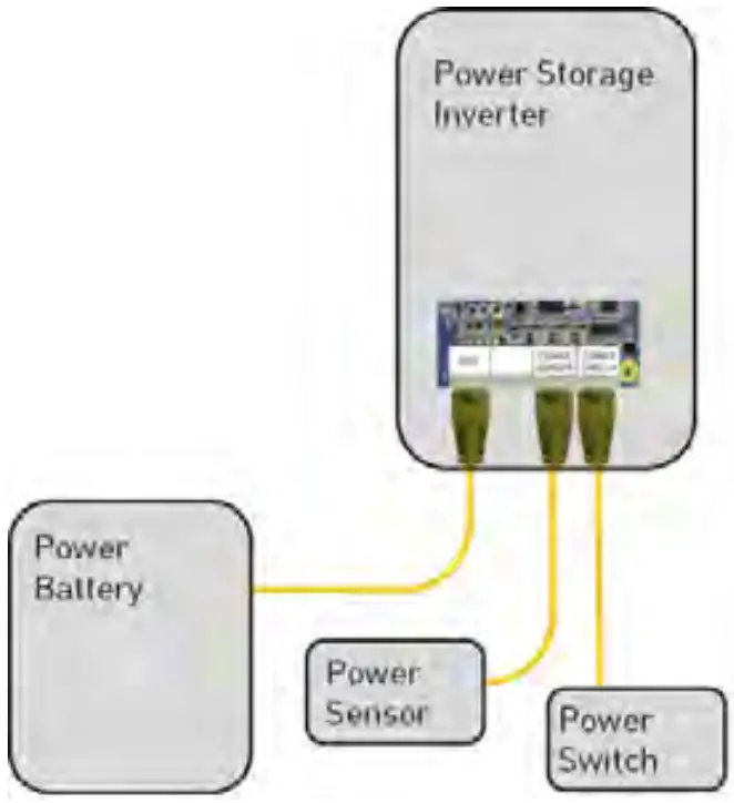
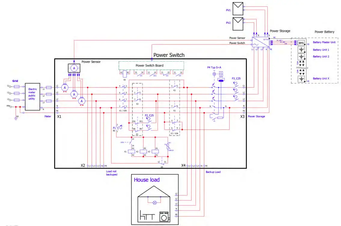
Connection – Power Switch
![]() NOTICE This Section applies only in use with a RCT Power Switch and battery system.
NOTICE This Section applies only in use with a RCT Power Switch and battery system.
![]() NOTICE Please note for a correct function of the Power Switch is only possible if the entire installation is as TN-C-S- or TN-S system!
NOTICE Please note for a correct function of the Power Switch is only possible if the entire installation is as TN-C-S- or TN-S system!
| Item | Description |
| 1 | Switch off the system [show section 9]. |
| 2 | Install the Power Switch in the service connection box or in the near. |
| 3 | Connect the Power Sensor and Power Switch via patch cable with the Power Storage DC at the RJ45 connector X403. |
| 4 | For further configurations please refer to user manual. |
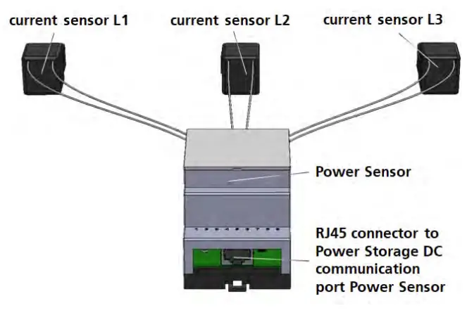
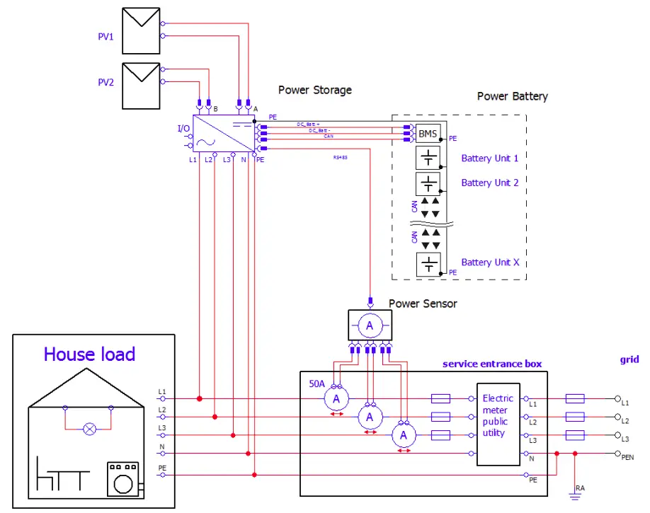
Connection – Power Sensor
![]() NOTICE The Power Storage DC system functionality depends on energy consumption measurement. This section applies only in use with a Power Sensor.
NOTICE The Power Storage DC system functionality depends on energy consumption measurement. This section applies only in use with a Power Sensor.
| Item | Description |
| 1 | Place the Power Sensor in the service entrance box. |
| 2 | Click the three current sensors around the phases L 1, L2 and L3 wires in the service entrance box. [The order and direction of installation is not important]. |
| 3 | Connect the Power Sensor via Patch cable to the Power Storage DC at the RJ45 connector X403 “Power Sensor” [see fig. 4]. |
| 4 | For further configurations please refer to user manual. |
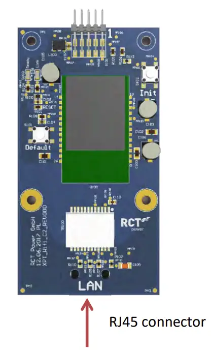
Connection – Ethernet-Interface
In addition to Wi-Fi-communication, the Power Storage DC offers the option to communicate via an Ethernet interface after initial start-up.
For this, a corresponding network cable [at least Cat5e] must be connected to the Power Storage DC and the corresponding terminal [preferably a router].
The configuration of this connection is made via the menu item “network settings” in the RCT Power App and is explained in the manual.
| Item | Description |
| 1 | Open cable entry [Fig. 1, d] and feed the cable. |
| 2 | Select correct port, insert cable in RJ45 connector. |
Commissioning
Ensure proper mechanical an electrical installation before commissioning the solar inverter. Check the cables to ensure, that they are in sound condition.
Always disconnect the mains connection first by switching off the corresponding mains fuse and before disconnecting the solar generator side by opening the DC load break switch.
The DC-connectors on the solar generator side must not be disconnected under load.
First turn the DC load break switch to position “0” and always switch off battery first! To ensure proper function of the DC system a RCT Power Sensor is required which transmits the grid feed-in power to the inverter.
If a storage system already exists this information can also be transmitted by networking via LAN / WLAN and thus dispenses with the RCT Power Sensor.
Further configuration inter alia for the networking of RCT Power devices via LAN/ WLAN can be found in the manual on our website www.rct-power.com.
Switch on Inverter
| Item | Description |
| 1 | Establish grid connection via the external circuit breaker. |
| 2 | Switch on the solar generator voltage by closing the DC load break switch [position 1l. The solar inverter starts operating, when the input voltage level and power is adequate. |
![]() NOTICE Please note that the inverter is powered by PY modules. Accordingly a start of the power supply and thus commissioning only with sufficient irradiation is possible.
NOTICE Please note that the inverter is powered by PY modules. Accordingly a start of the power supply and thus commissioning only with sufficient irradiation is possible.
Access to the inverter
![]() NOTICE The Solar Inverter is equipped with an internal Wi-Fi unit. To set up Solar inverter you need to access via Wi-Fi due to the suitable Android APP. The Android APP is the central user interface for commissioning. ensures easy data collection and troubleshooting.
NOTICE The Solar Inverter is equipped with an internal Wi-Fi unit. To set up Solar inverter you need to access via Wi-Fi due to the suitable Android APP. The Android APP is the central user interface for commissioning. ensures easy data collection and troubleshooting.
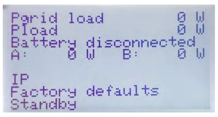
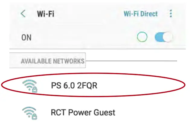
- Activate Wi-Fi on your smart phone [or tablet computer).
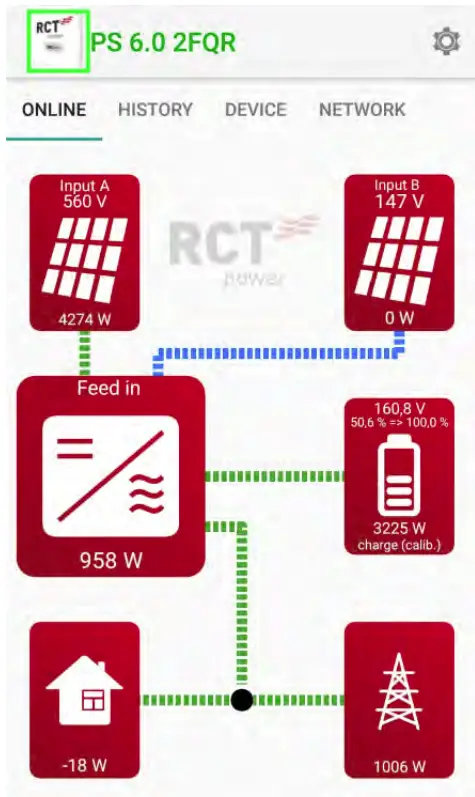
- Connect with SSID identical with the name of the Power Storage on inverter display via Wi-Fi. (e.g. PS 6.0 2FQR].
 If the Inverter is already in a network via Wi-Fi, connect to the network.
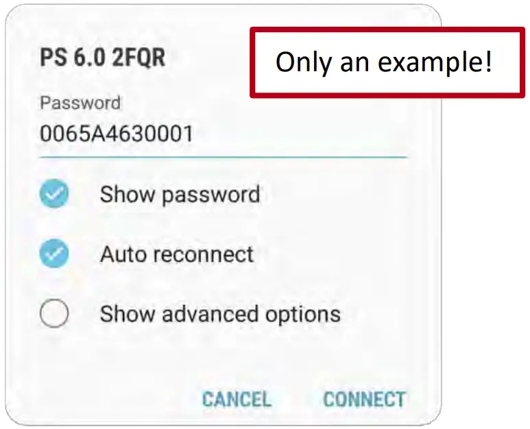
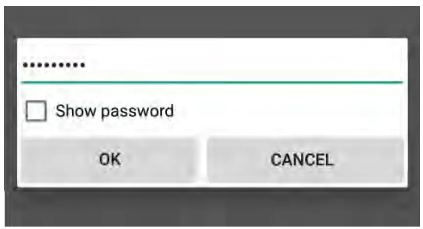
- If you connect the first time with a device to the inverter you need a password.
The password corresponds to the serial number of your device [see display or name plate).
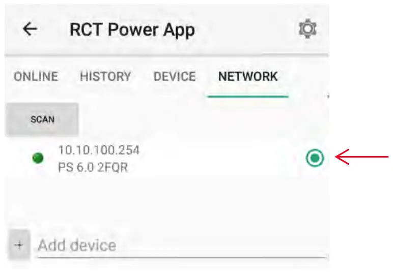
- Start “RCT Power APP”.

- Switch to tab ‘”Network” and press “Scan”.
- Activate “10.10.100.254” [or if you have renamed the device choose this] by choosing radio button.

- If the connection is made with an inverter, the name is displayed on the head and the icon is edged.


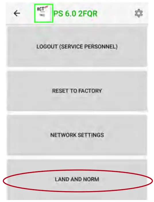
Configure inverter
- Press


- Enter setup procedure by “Login” with suitable password for installer-level

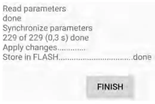
- Choose “Land and Norm”, select appropriate norm and “apply”.

- Wait during parameters are synchronizing and stored. When finished press “Finish”. Return to the main menu.


Configure plant peak power and power reduction
In order to obtain the maximum yield from the solar system, it is possible to configure a dynamic power reduction.
There is no additional equipment required for this configuration apart from the Power Sensor. The feed-in power is measured at the mains connection point and is only capped if the excess power exceeds the set value.
- Switch to .. Device” and tap on .. Settings” and in following on .. Device settings”.
- Enter your system peak power and the required limiting factor in the following screen. Please note that after entering the value you confirm it on the keyboard [depending on the device “Enter” or “Ok”].

The corresponding field then briefly turns red and white again.
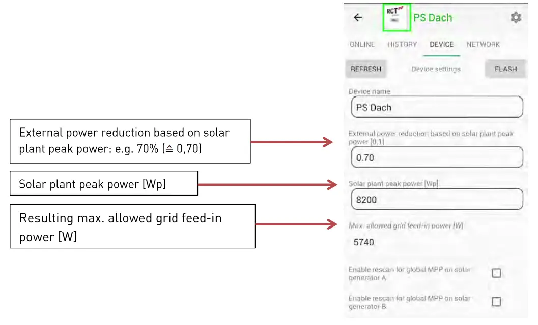
Please note: If your system contains several devices you must the enter peak power of the combined system.
Changes to settings are only saved permanently if they are flashed to the inverter’s memory! It is therefore essential to press “FLASH” to confirm your settings changes. They will otherwise be lost when the inverter is switched off.
Configure battery
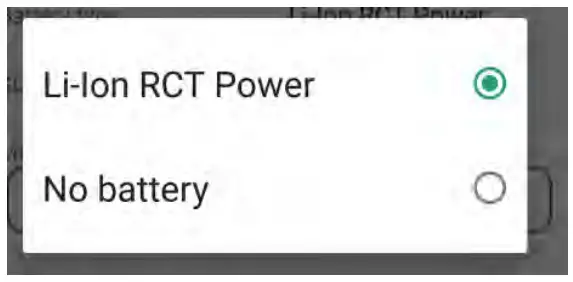
- Go to “Device” and click on “Settings”, then click “Battery”.
- Click on “Battery type” and select “Li-Ion RCT Power” or your corresponding battery type.

- Turn on the battery by setting the battery ON/ OFF switch to ”1″.
- The inverter now connects to the battery. After the inverter checked the specifications and connected to the battery, it starts to arrange the current sensor.
Once this is done, the inverter resets and flashes the settings.
After that he starts to calibrate the battery.
The battery will be charged to 100%, this may take several hours.
[When calibrating, power may be used out from the grid to speed up the process if the power is insufficient.]
When calibration is complete, the system automatically switches to compensation mode.
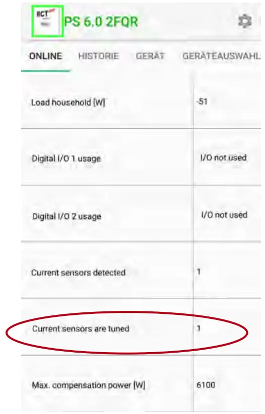
- Check if the Power Sensor has been arranged. Go to the homepage ··online” and press the
 symbol and check the display.
 Current sensors are tuned= 1
Note: For further information on installation and operation, please refer to the detailed user manual, which can be obtained from our website www.rct power.com.
How to switch off the system
- Locate DC switch [Fig. 1, bl and turn to “0” position and switch off the battery with the ON/OFF switch to “0”.
- Switch off circuit breaker, main breaker or fuse for disconnecting inverter from utility grid.
- Wait min. 10 minutes until capacitors have discharged.
- Remove the battery- and DC connectors[Fig. 1, c & h].
Press latches of male plug together to unlock and pull off DC plugs.
Technical Data
| Power Storage DC | 4.0 | 6.0 |
| Order Number | 110-0001 | 110-0002 |
| DC-INPUT | ||
| Max. recommended DC power | ||
| [South/ East-West]* | 5,4 kW/ 6 kW | 8,1kW / 9 kW |
| MPPT | 2 [paralleling possible] | |
| Input per MPPT | 1 | |
| Maximum DC current per MPPT | 12 A I 24 A in parallel mode] | |
| Rated DC voltage | 700 V | |
| DC start up voltage/ power | 150 V / 40 W | |
| DC voltage range | 140 V … 1000 V | |
| MPP voltage range | 265 V … 800 V | |
| Maximum voltage DC | 1000 V | |
| Connector type | Weid muller PV-Stick [MC4 compatible] * Depending on orientation, inclination and place of installation. | |
| BATTERY-INPUT | ||
| DC voltage range | 120 V … 600 V | |
| Maximum charge/ discharge current | 20 A/ 20 A | |
| Maximum charge/ discharge power | 9220 w / 4000 w | 9220 w / 6000 w |
| Connector type | Weid muller PV-Stick [MC4 compatible] | |
| AC-OUTPUT | ||
| Rated AC output power | 4000 W | 6000 W |
| Maximum active power | 4000 W | 6000 W |
| Maximum apparent power | 6000 W | 6000 W |
| Nominal AC current per phase | 5,8 A | |
| Maximum AC current per phase | 9,1 A | |
| Rated frequency | 50 Hz/ 60 Hz | |
| Frequency range | 45 Hz … 65 Hz | |
| Max. switch-on current | 9,1 A, 0,1ms | |
| Max. fault current [RMS] | 285 mA | |
| Rated AC voltage | 230V / 400 VIL 1, L2, L3, N, PE] | |
| AC voltage range | 180V … 290V | |
| Total harmonic distortion [THO] | < 2% at rated power | |
| Reactive power factor [cos phi] | 1 [adjustable range 0,8 cap …. 0,8 ind ] | |
| Anti-islanding operation | Yes | |
| Earth fault protection | RCD | |
| DC-current injection | < 0,5% In | |
| Required phases, grid connections | 3 [L1, L2, L3, N, PE] | |
| Number of feed-in phases | 3 | |
| Grid voltage monitoring | 3-phase | |
| Type of AC connection | Spring clamps | |
| PERFORMANCE | ||
| Stand-by consumption | < 4.0 W | |
| Maximum efficiency IPV – Grid] | 98, 16% | |
| European efficiency IPV – Grid] | 97,6% | |
| Maximum efficiency IPV – Battery – Grid] | 95,9% | |
| Topology | Transformer less | |
| OTHER | ||
| PV – DC-switch | Integrated | |
| DC overvoltage category | II | |
| AC overvoltage category | III | |
| Data interface | WIFI, LAN, RS485, Multifunctional dry contact, 4 x digital in, 2 x digital in/out | |
| Display | LCD dot matrix 128 x 64 with backlight | |
| Cooling | Convection | |
| IP degree of protection | IP 42 | |
| Max. operating altitude | 2000 m | |
| Max. relative humidity | 5 – 85% I non condensing] | |
| Typical noise | < 35 dB | |
| Operating temperature range | -25°C … 60°C 140° at full load] | |
| Type of installa tion | Wall mounting | |
| Dimensions I height x width x depth] | Wall mounting 570 x 585 x 200 mm | |
| Weight | 30 kg | |
| SAFETY/STANDARDS | ||
| Protection class | 1 | |
| Overload behavior | Working point adjustment | |
| Certificates | CE, VDE-AR-N 4105:2018-1 1, EN 50549 Further certificates : www.rct-power.com | |
| EMC | EN61000-6-2, EN61000-6-3, EN61000-3-2, EN61000-3-3 | |
| Safety | EN/IEC62109-1, EN/IEC62109-2 | |
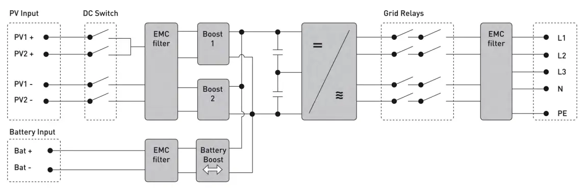
BLOCK DIAGRAM
RCT Power GmbH
Line Eid S t r. 1
78467 Konstanz, Deutschland
RCT~ Tel .: +49 [01 753199677- 0
Mail: info[at]rctpower.com
power
01/2021
Internet: www.rct-power.com