![]() FROM MAXEON SOLAR TECHNOLOGIES
FROM MAXEON SOLAR TECHNOLOGIES
QUICK INSTALLATION GUIDE
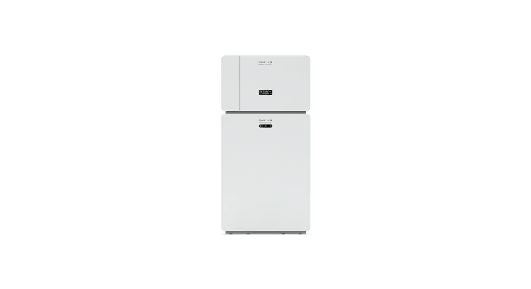
MODEL: RESERVE-INV-1-P5-L1-INT
548268 Rev. A
 Safety and Installation Instructions for SunPower Reserve
https://www.sunpower.maxeon.com/int/InstallGuideReserve
Product Overview
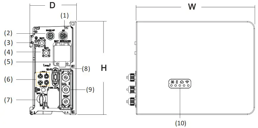
| (1) Grid connector (2) Backup connector (3) BAT + (4) BAT (5) Battery circuit breaker | (6) PV connectors (7) PV switch (8) Wi-Fi port (9) Communication ports (10) LED display |
Dimension: W×H×D=483×380×190mm
Confirmation of Accessories and Tools
- Scope of Delivery

- Additional Materials Required for Installation

- Installation Tools


Installing the Inverter
Before installing the inverter ensure that the battery is properly installed. For more details refer to Battery Quick Installation Manual or Safety and Installation Instructions.
![]() Electric Shock Hazard
Electric Shock Hazard
Before doing any electrical connection, ensure the PV switch, AC and BAT circuit breaker are switched OFF and cannot be reactivated.
Electrical Connections
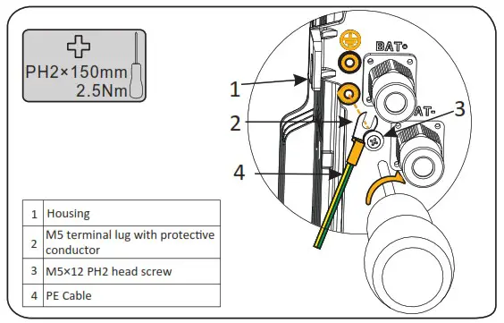
- Installing the PE cable
 DANGER
You must protect each inverter with an individual AC circuit breaker in order to ensure that the inverter can be disconnected safelyDescription Breaker Specification Grid side 32A/40A Backup side 32A  Warning
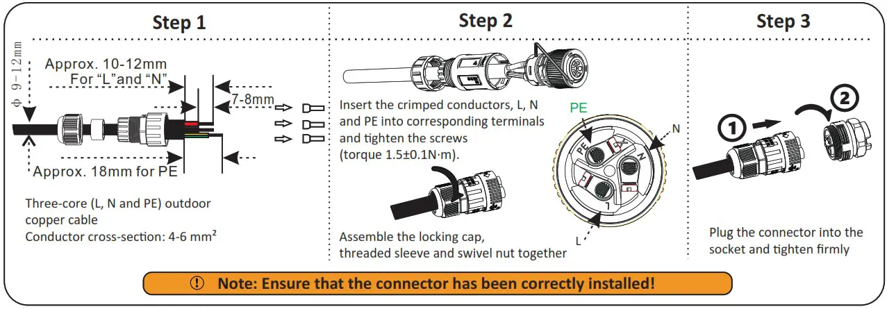
The max. allowable grid circuit breaker specification is 40A. At the same time, the cross section of the copper conductor for grid connection must be 6mm² (in some countries: 8mm²). You should use APP or Web monitoring to do the right setting, otherwise it would increase the danger of the circuit breaker tripping under normal operating conditions. - Connecting the Grid Power Cable

- Connecting the AC Backup Power Cable

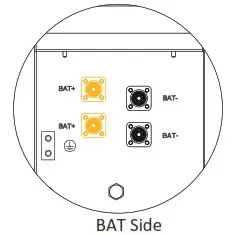
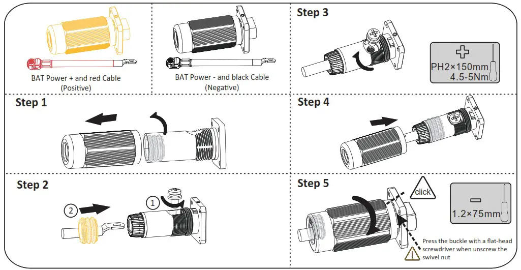
- Connecting the BAT Power Cable
 1. Switch OFF the battery breaker which is located on the right side of the battery
2. Connect the BAT – wire first (Black) then the BAT + wire (Red)
 DANGER
Danger to life due to short-circuiting of the battery
• Touching a shorted battery connection may result in lethal injuries due to electric shock and massive energy release.
• Switch off the battery breaker which is located on the lower lest of the inverter.
• Connect both ends of one battery power cable completely before connecting the next power cable to avoid short-circuiting of the positive and negative battery power cables.


Communication Connection
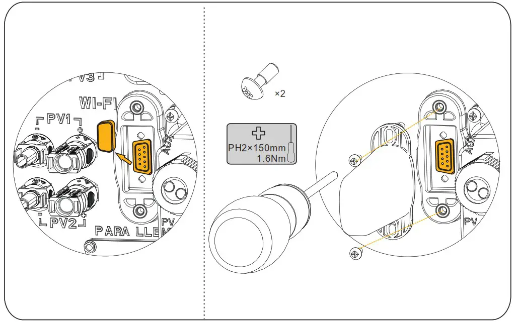
- Wi-Fi module Connection

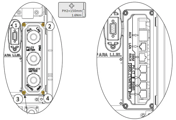
- AUX / LAN/PV-CT Meter/DRM/GRID-CT Meter/RS485/BMS Connection
Communication connection port as follows: Keep the screws on the cover (x4)
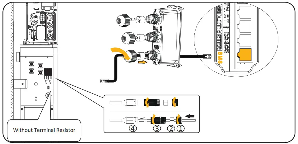
ITEM/NO 1 2 3 4 5 6 7 8 BMS NC RS485 A4 NC CAN1 H CAN1 L NC RS485 B4 NC RS485 12V NC GND RS485_B5 RS485_A5 NC NC NC GRID CT/METER GRID CT- GRID CT+ RS485_A7 NC NC RS485 B7 NC NC PV CT PV CT- PV_CT+ RS485_A7 NC NC RS485 B7 NC NC DRM DRED1/5 DRED2/6 DRED3/7 DRED4/8 REFGEN/O COMLOAD/O AUX DO1 NO D01 COM Doi NC DI NEGATIVE DI POSITIVE GND - Wiring the Communication Cables between Inverter and Battery(EMS)

 Keep the screws on the cover (x4)
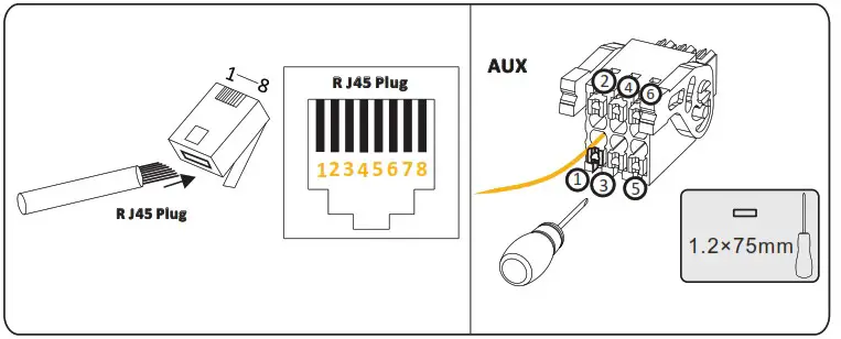
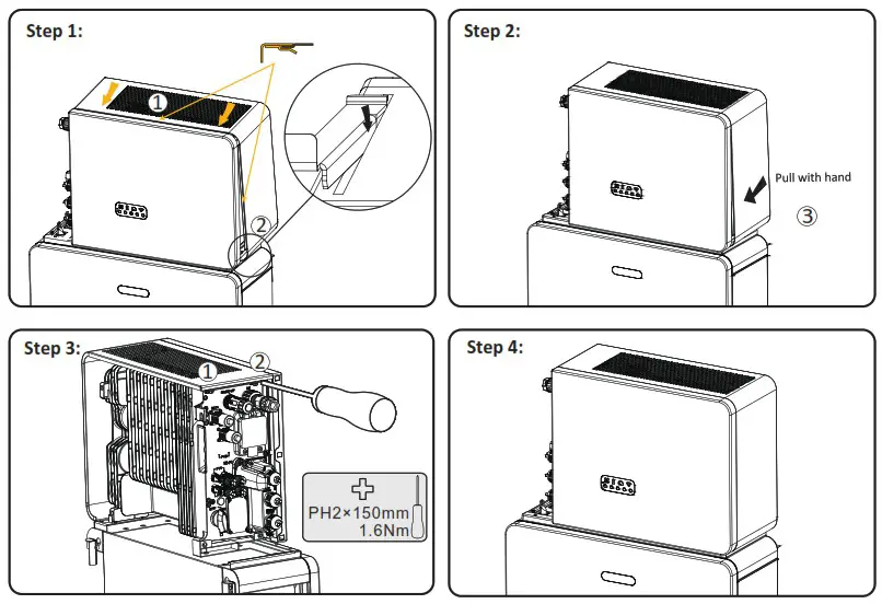
Install top cover
Warning
Before turning on power, ensure that all the electrical connections are secure.
Commissioning
To set up the inverter as part of a SunPower Reserve installation, follow the commissioning steps as outlined in the Reserve Safety and Installation Instructions.
Power ON / OFF the Product Procedure
Warning
Ensure a reliable and correct installation and electrical connection before power on.
Power ON procedure
- Switch on the battery breaker of the batteries.
- Switch on the battery breaker which is on the left side of the inverter.
- Press the battery button, if there are more than one battery, the button for each battery should be pressed within 5s of previous.
- Switch on the breaker between the grid port of the inverter and the grid.
- Switch on the AC breaker between the backup port of the inverter and the loads.
- Switch on the PV switch on the left side of the inverter.
- Switch on the PV switch between the external PV-inverter and the grid if there is any.
Power OFF procedure
- Switch off the AC breaker between the backup port of the inverter and the loads.
- Switch off the PV switch is on the left side of the inverter.
- Switch off the PV switch between the external PV-inverter and the grid if there is any.
- Long press the power button of the battery pack for 6 seconds, then switch off the battery breaker of the battery pack.
- Switch off the battery breaker which is on the left side of the inverter.
- Switch off the AC breaker between the grid port of the inverter and the grid.
For more information, refer to the Safety and Installation Instructions.
![]() Disclaimer
Disclaimer
This Quick Installation Manual is not replacing the Safety and Installation Instructions, it is a short introduction to the product installation. The reference remains the Safety and Installation Instructions
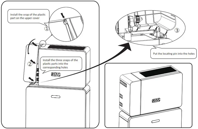
Installing the plastic part
Make sure all the wiring is secure and the system is working properly and then install the plastic parts on the left side of the inverter.
Refer to Safety and Installation Instructions to commission the whole system.
NEED MORE HELP?
If you would like to contact us directly, please visit our official website https://sunpower.maxeon.com for more information.


 Installation Guide")


