
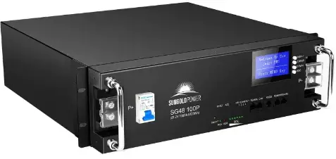
Sun Gold Power SG48100P Battery System Home Storage
Document description
This specification covers the performance indexes, technical requirements and safety issue of the 48V100Ah
Definition of Terms
| BMS | Battery Management System |
| DOD | Depth Of Discharge |
| EOL | End Of Life |
| OCV | Open Circuit Voltage |
| SOC | State Of Charge |
| SOH | State Of Health |
| EMC | Electro Magnetic Compatibility |
| Nominal voltage | Appropriate voltage approximation to identify or identify a cell or an electrochemical system. |
| Capacity | (The amount of power a battery can provide when fully charged under specified conditions. Usually expressed in Ah.) |
| Energy | The energy that can be provided by a fully charged battery under specified conditions. Usually expressed in Wh or kWh. |
|
Unit | “V” (Volt) ( Voltage unit) “A” (Ampere) (Current unit) “Ah” (Ampere-Hour) (unit of charge) “Wh” (Watt-Hour) (electrical energy unit) “Ω” (Ohm) (resistance unit) “ °C” (degree Celsius) (temperature unit) “mm” (millimetre) (length unit) “s” (second) (Time unit) “kg” (kilogram) (Weight unit) “Hz” (Hertz) (Frequency unit) |
Battery system performance parameters
| No. | Item | Technical parameter | Note |
| 1 | Battery Type | Lithium iron phosphate battery | / |
| 2 | Rated capacity | 100Ah | @25℃±2,0.5C,100%DOD |
| 3 | Nominal voltage | 51.2V | |
| 4 | Recommended charging voltage | 54.5V | |
| 5 | Charging Limited Voltage | 42V | |
| 6 | SOC working range | 0~100% | Recommended range of use: 20%~95% |
| 7 | Standard discharge current | 50A |
| 8 | Maximum continuous discharge current | 100A | |
| 9 | Standard charging current | 50A | |
| 10 | Maximum continuous charge current | 100A | |
| 11 | Maximum cut-off voltage for charging | 57.6V | |
| 12 | Charge cut-off current | 5A | 0.05C magnification |
| 13 | Disharge cut-off voltage | 43.2V | |
| 14 | PACK cycle life | ≥7000 | 80%DOD 25℃±2℃, 0.5C charge/0.5C discharge |
| 15 | Thermal management method | Natural heat dissipation | |
| 16 | IP protection class | IP31 battery box | |
| 17 | Flammability rating | plastic parts UL94 V-0 | |
| 18 | Total system mass | Around 43KG | |
| 19 | Battery system shell material | BLACK Q235A | Color can be customized |
| 20 | Shipping SOC | SOC45-55% | |
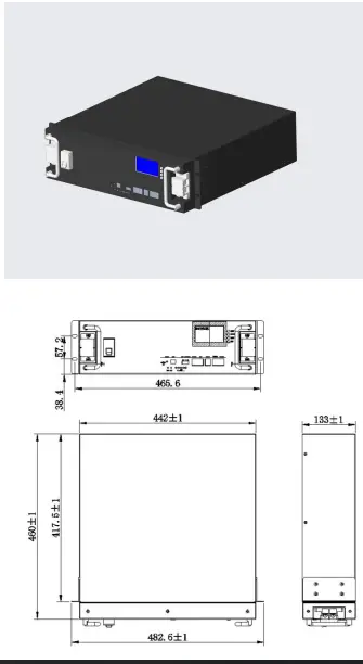
| 21 | Dimension(L*W*H mm) | R442*460*133(3U)±1mm | |
| 22 | Design life | 15 Year | |
| 23 | Parallel function | Supports up to 16 batteries in parallel | |
| 24 | Anti-theft function | sensor G-sensor anti-theft function | |
| 25 | Display function | English smart display | |
| 26 | Charging current limit function | Current limit 20A | Charging current limit can be set according to customer requirements |
|
27 |
Communication mode | RRS232 | Communication mode can be set according to customer requirements |
| RRS485 | |||
| RCAN | |||
| 28 | communication protocol | Support multiple protocols | Communication protocol can be set according to customer requirements |
| 29 | Storage ambient temperature | -10~+45℃ | Recommended storage temperature: 0~+30℃ |
| 30 | Working temperature | Battery charging:0~45℃ Battery discharging:-20~ +60℃ | |
| 31 | Relative humidity of working environment | ≤95 | Best Use Relative Humidity:≤85% |
Outline and Structural Dimensions of Battery System
Definition of battery system interface
Panel Schematic
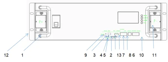
Module Panel Description
| NO | Function definition | Function Description | Note |
| 1 | handle | Carrying handle | |
| 2 | SOC | Capacity status light | Six green LED lights to show the current charge of the lithium battery pack |
| 3 | ALM | Alert | Red LED light, normally off under normal conditions, always on under fault conditions, and a voice prompt |
| 4 | RUN | Run | Green light, always on when the product is running |
| 5 | ADD | DIP switch | Use 4 bit binary DIP switch (optional) to set address allocation when products are used in parallel, |
|
6 |
RS232 |
RS232 communication | Uplink communication port, RS232 communication mode when uploading data, data content includes system parameters, system status and alarm information. The rate of 9600bps is generally used. Note: Wiring definitions are implemented in accordance with BMS product specifications |
| 7 | RS485 | RS485 communication | RS485 communication method |
| 8 | CAN | CAN communic | CANcommunication method |
| 9 | RESET | Reset | When the product is in an abnormal state or in a hibernation state, the product can be restarted and woken up through the reset button to ensure the stable operation of the system |
| 10 | Main panel | Shell | Sheet metal thickness 1.5mm, galvanized frosted paint, color: black |
| 11 | Terminals | Input and output terminals | Battery positive and negative output terminals |
| 12 | Hanging ears | Mounting ears | The spacing is implemented according to the national standard |
|
13 |
dry contact terminal |
Load output port | example: definition: Dry contact 1-PIN1 to PIN2: normally open, closed during fault protection Dry contacts 2-PIN3 to PIN4: normally open, SOC<5%, closed for low battery alarm. |
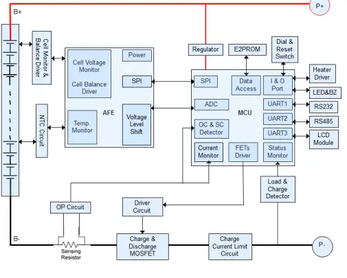
Functional block diagram
The functional block diagram is shown in the figure below
Battery Management System Specifications
Basic parameter settings
| NO. | Indicator item | Factory default parameters | Is it possible to set | Note | |
|
1 |
Cell overcharge protection | Cell overcharge alarm voltage | 3600mV | Can be set | |
| Cell overcharge protection voltage | 3650mV | Can be set | |||
| Cell overcharge protection delay | 4.0S | Can be set | |||
| Single Overvoltage Protection Released | overcharge protection release voltage Cell | 3380mV | Can be set | ||
| Capacity release | SOC<96% | Can be set | |||
| Discharge release | > 1A | ||||
|
2 | Cell overdischarge protection | Cell over-discharge alarm voltage() | 2700mV | Can be set | After 30 seconds of over- discharge protection, if it still cannot recover, it will enter low |
| Cell over-discharge protection voltage | 2500mV | Can be set | |||
| Monomer over-discharge protection delay | 1.0S | Can be set | |||
| Cell over- discharge | Cell over-discharge protection release voltage | 2800mV | Can be set | ||
| protection released | (Release when charging) | Plug into the charger to activate | power consumption mode | ||
|
3 | Overall overcharge protection | Overall overcharge warning voltage | 57.6V | Can be set | |
| Overall overcharge protection voltage | 58.4V | Can be set | |||
| Overall overcharge protection delay | 1.0S | Can be set | |||
| Overall overvoltage protection released | Overall overcharge protection release voltage | 54.1V | Can be set | ||
| Capacity release | SOC<96% | Can be set | |||
| Discharge release | > 1A Discharge current > 1A | ||||
|
4 |
Overall overdischarge protection | Overall over-discharge warning voltage | 43.2V | Can be set | After 30 seconds of over- discharge protection, if it still cannot recover, it will enter low power consumption mode |
|
Overall over-discharge protection voltage |
40V |
Can be set | |||
| Overall over-discharge protection delay | 1.0S | Can be set | |||
| Overall over- discharge protection released | Overall over-discharge protection release voltage | 44.8V | Can be set | ||
| Release when charging | Plug into the charger to activate | ||||
| Charging current limit function | Charging current limit | 20A | |||
|
5 | Charge overcurrent protection | Charge overcurrent 1 alarm current | 105A | Can be set | Appearing 10 times in a row will lock the status and will no longer automatically release |
| Charge overcurrent 1 protection current | 110A | Can be set | |||
| Charge overcurrent 1 protection delay | 1.0S | Can be set | |||
| Charging overcurrent 1protection released | Automatic release) | 1min Automatically cancel after 1min | |||
| Discharge release | > 1A Discharge current > 1A | ||||
|
6 | Discharge overcurrent 1 protection | Discharge overcurrent 1 alarm current) | 105A | Can be set | Appearing 10 times in a row will lock the status and will no longer automatically release |
| Discharge overcurrent 1 protection current) | 110A | Can be set | |||
| Discharge overcurrent 1 protection delay | 1.0S | Can be set | |||
| Discharge overcurrent 1 protection released | Automatic release | 1min Automatically cancel after 1min | |||
| Charge release | > 1A Charge current > 1A | ||||
|
7 | Discharge overcurrent 2 | Discharge overcurrent 2 protection current | ≥120A | Can be set | Appearing 10 times in a row will lock the status and will no longer automatically |
| Discharge overcurrent 2 protection delay | 100mS | Can be set | |||
| Discharge | Automatic release | 1min | |||
| overcurrent 2 protection released | Automatically cancel after 1min | release | ||||
| charge release | > 1A Charge current > 1A | |||||
|
8 |
Short circuit protection | Short circuit protection function | (Have) | |||
| Short circuit protection current | ≥350A | |||||
| Short circuit protection delay | ≤300US | |||||
|
Short circuit protection released | When there is charging, the short circuit protection is released | |||||
| After the load is removed, it will automatically disarm | ||||||
|
9 | MOS high temperature protection | MOS over temperature alarm temperature) | 90℃ | Can be set | ||
| MOS over temperature protection temperature) | 115 ℃ | Can be set | ||||
| MOS protection release temperature) | 85℃ | Can be set | ||||
|
10 |
Cell temperature protection | Charging low temperature warning temperature) | 0℃ | Can be set | ||
| Charging low temperature protection temperature) | -5℃ | Can be set | ||||
| Charging low temperature protection release temperature | 0℃ | Can be set | ||||
| Charging high temperature alarm temperature | 50℃ | Can be set | ||||
| Charging high temperature protection temperature) | 55℃ | Can be set | ||||
| Charging high temperature protection release temperature | 50℃ | Can be set | ||||
| Discharge low temperature alarm temperature | -15℃ | Can be set | ||||
| Discharge low temperature protection temperature | -20℃ | Can be set | ||||
| (Discharge low temperature protection release temperature | -15℃ | Can be set | ||||
| Discharge high temperature alarm temperature | 60℃ | Can be set | ||||
| Discharge high temperature protection temperature | 65℃ | Can be set | ||||
| Discharge high temperature protection release temperature | 55℃ | Can be set | ||||
|
11 |
Ambient temperature alarm | Ambient low temperature alarm temperature | -15℃ | Can be set | ||
| Ambient low temperature protection temperature | -20℃ | Can be set | ||||
| Ambient cryogenic protection release temperature | -15℃ | Can be set | ||||
| Ambient high temperature alarm temperature | 65℃ | Can be set | ||||
| Ambient high temperature protection temperature | 75℃ | Can be set | ||||
| Ambient high temperature protection release | 65℃ | Can be set | ||||
| temperature | |||||
| 12 | Current consumption | Self-consumption current during operation | ≤45mA((with display) | ||
| ≤40mA(without display) | |||||
| Low power mode current | ≤200μA | ||||
| 13 | Equalization function | Equalization turn-on voltage | 3500mV | Can be set | |
| Open differential pressure | 30mV | Can be set | |||
| 14 | Capacity default settings | Low battery warning | SOC<5% | Can be set | (No alarm when charging) |
| Full capacity setting | 100AH | Can be set | |||
| 15 | Sleep function | Sleep voltage | 3150mV | Can be set | |
| Delay | 5min | Can be set | |||
| 16 | Differential pressure alarm | Overpressure alarm | 800mV | ||
| Overpressure recovery | 500mV | ||||
| 17 | Cell failure protection | Monomer differential pressure | >1V Voltage difference>1V | Charge and discharge are not allowed | |
| 18 | Full charge judgment | Full charge voltage | 56V | ||
| Cut off current | 2A | ||||
Interface
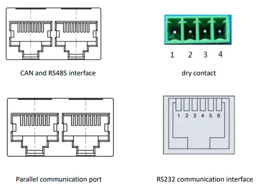
Interface Definition
| RS232–Using 6P6C vertical RJ11 socket | |
| RJ11 | Definition description |
| 2 | NC |
| 3 | TX |
| 4 | RX |
| 5 | GND |
RS485 and CAN interface
| RS485–Using 8P8C vertical RJ45 socket | RS485–Using 8P8C vertical RJ45 socket | ||
| RJ45Pin | Definition description | RJ45 Pin | Definition description |
| 1、8 | RS485-B | 9、16 | RS485-B |
| 2、7 | RS485-A | 10、15 | RS485-A |
| 3、6 | GND | 11、14 | GND |
| 4、5 | NC | 12、13 | NC |
Communication description
RS232 communication
The BMS can communicate with the host computer through the RS232 interface, so as to monitor various information of the battery on the host computer side, including battery voltage, current, temperature, status, SOC, SOH and battery production information, etc. The default baud rate is 9600bps.
RS485 communication
With dual RS485 interface, you can view the information of PACK, the default baud rate is 9600bps. To communicate with the monitoring device through RS485, the monitoring device is used as the host to poll data according to the address, and the address setting range is 2~15.
CAN communication
Product function and performance description
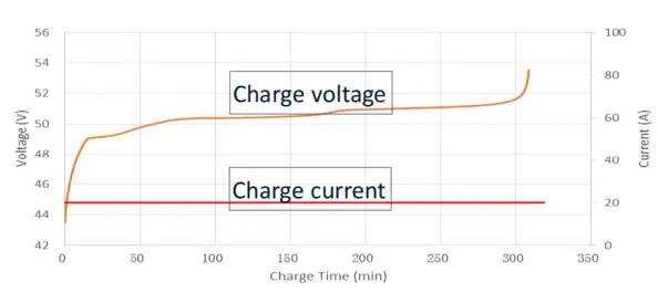
Charging performance
- Standard charging current: (25℃): example:0.2C(20A)
- Standard charging voltage: 54V
- Standard charging mode and charging curve:
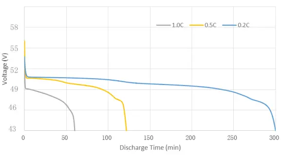
Discharging performance
Discharge curve at different magnification
Using & Maintenance Suggestions
LED indication description
Table 1 LED working status indication
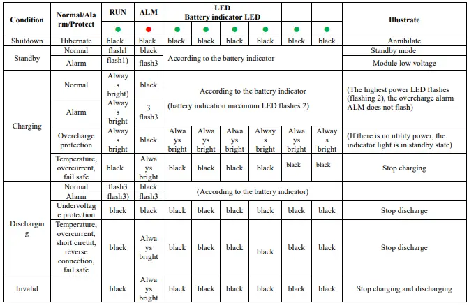
Table 2 Description of capacity indication
| Condition | Charging | Discharging | |||||||||||
| Capacity indicator | L6● | L5● | L4● | L3● | L2● | L1● | L6● | L5● | L4● | L3● | L2● | L1● | |
|
Electricit y(%) |
0~17% |
black |
black |
black |
black |
black | flash2 |
black |
black |
black |
black |
black | Always bright |
|
17~33% |
black |
black |
black |
black |
flash 2 |
Alway s bright |
black |
black |
black |
black |
Alway s bright |
Always bright | |
|
33~50% |
black |
black |
black |
flash 2 |
Alway s bright |
Alway s bright |
black |
black |
black |
Alway s bright |
Alway s bright |
Always bright | |
|
50~66% |
black |
black |
flash 2 |
Always bright |
Alway s bright |
Alway s bright |
black |
black |
Alway s bright |
Alway s bright |
Alway s bright |
Always bright | |
|
66-83% |
black |
flash 2 | Alway s bright | Always bright | Alway s bright | Alway s bright |
black | Alway s bright | Alway s bright | Alway s bright | Alway s bright | Always bright | |
|
83-100% |
flash 2 | Alway s bright | Alway s bright |
Always bright | Alway s bright |
Alway s bright | Alwa ys brigh t | Alway s bright | Alway s bright | Alway s bright | Alway s bright |
Always bright | |
| Running lights● | Always bright | flash3 | |||||||||||
Table 3 LED flashing description
| Flashing method | Bright | Black |
| flash 1 | 0.25S | 3.75S |
| flash 2 | 0.5S | 0.5S |
| flash 3 | 0.5S | 1.5S |
Note: The LED indicator alarm can be enabled or disabled through the host computer, and the factory default is enabled.
Buzzer action description
- In case of failure, it will beep for 0.25S every 1S;
- During protection, it will beep for 0.25S every 2S (except for overvoltage protection);
- When alarming, it will beep every 3S for 0.25S (except overvoltage alarm);
- The buzzer function can be enabled or disabled by the host computer, and the factory default is disabled.
Key Description
- When the BMS is in the dormant state, press the button (3~6S) and release it, the protection board will be activated, and the LED indicators will light up in sequence from “RUN” for 0.5 seconds.
- When the BMS is activated, press the button (3~6S) and release it, the protection board is put to sleep, and the LED indicators light up sequentially for 0.5 seconds from the lowest battery light.
- When the BMS is activated, press the button (6~10S) and release it, the protection board will be reset, and all the LED lights will light up at the same time for 1.5 seconds.
After the BMS is reset, it still retains the parameters and functions set by the host computer. If it is necessary to restore the initial parameters, it can be achieved through the “restore default value” of the host computer, but the relevant operation records and stored data remain unchanged (such as power, cycle times, etc.). , protection records, etc.).
Sleep and wake up
hibernate: When any of the following conditions are met, the system enters a low-power mode:
- The single or overall over-discharge protection has not been released within 30 seconds.
- Release the button after pressing the button for 3 seconds.
- The minimum cell voltage is lower than the sleep voltage, and the duration reaches the sleep delay time (at the same time, no communication, no protection, no balance, and no current are satisfied).
- The standby time is more than 24 hours (no communication, no charging and discharging, no mains power).
- Forced shutdown through the host computer software.Before entering the sleep mode, make sure that the input terminal is not connected to an external voltage, otherwise it will not be able to enter the low power consumption mode.
wake
When the system is in low-power mode and meets any of the following conditions, the system will exit the low-power mode and enter the normal operation mode:
- Connect the charger, the output voltage of the charger must be greater than 48V.
- Press the button for 3S and release the button.
- Connect to the communication line and open the software of the upper computer (it enters the sleep state due to over-discharge protection, this method cannot wake up the protection board).
Remarks:
After the single or overall over-discharge protection, it enters the low-power mode, wakes up regularly every 4 hours, and turns on the charge and discharge MOS. If it can be charged, it will exit the dormant state and enter normal charging; if it cannot be charged after 10 consecutive automatic wake-ups, it will no longer automatically wake up.
When the system is defined as the end of charging, the recovery voltage is not reached after 2 days of standby (standby time setting value), and the charging is forced to resume until the end of charging again.
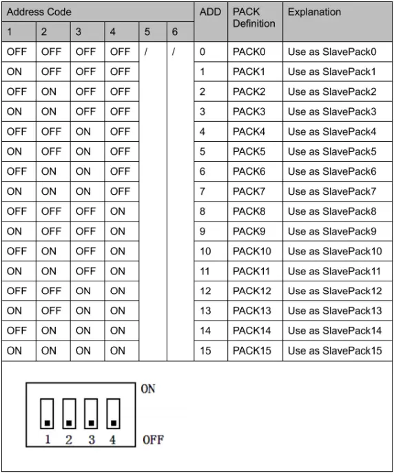
DIP switch settings
When the battery packs are used in parallel, different PACK can be distinguished by their hardware addresses, and the hardware address of each PACK in the entire battery stack is unique. The hardware addresses can be set in sequence through the DIP switches on the board. Refer to the following for the definition of the switches. surface.
The routine maintenance of the battery part can be carried out by referring to the table
| Period | Item | Treatment measures |
| Per month | (Operating environment) | Keep away from heat sources and avoid direct sunlight |
| Visual inspection | If the appearance is damaged, leaked or deformed, the faulty battery pack should be disconnected, photographed and replaced. | |
| Each quarter | Clean appearance | Clean the exterior with a cotton cloth. Due to the high voltage of the battery pack, care should be taken when cleaning. |
| Connection Status | l Check the bolts at each terminal and retighten them if they are loose.
l If the temperature of the connection line exceeds 40°C (feeling hot), check the cause | |
| Every half year | Voltage detection | l At the end of charging, measure and record the busbar voltage and the positive and negative terminal voltages of the battery pack. The voltages of the two are consistent. Otherwise, check whether the cable at the corresponding connection is faulty. l In the first year, real-time data collection at the end of discharge was performed at least every six months. l Beginning in the second year, on-site capacity determination will be conducted every three months. If a certain battery cell is frequently overcharged and over- discharged in the historical alarm information viewed through the RS232 interface, it means that the battery cell has touched the charging protection point and the discharging protection point for a long time. This situation may lead to insufficient backup time, it is recommended to replace it in time |
The final state of charge and discharge can be judged by the capacity light, refer to the definition of LED light capacity status light.
Packing List
| NO. | Material name | Specification/Module | Number |
| 1 | 48100Ah lithium iron phosphate battery | 48100 | 1 set/box |
| 2 | Positive and negative output lines | 25mm2 flame retardant cable, length 0.5m, crimp 25-6 copper noses at both ends, one red and one black. | 1 set/1 module |
| 3 | RS485 cascade communication line | 0.5 meters long, with RJ45 crystal heads at both ends. | 1root/2 modules |
| 4 | RS485 USB RS232 USB | 1.5 meters long, one end is the corresponding crystal head, and the other end is the USB interface. | 1 set/8 module |
| 5 | Product manual | / | 1 |
| 6 | Certificate | / | 1 |
| 7 | Hanging ear screw | M6*16(stud 16mm) | 4 |
| 8 | Dry contact terminal | Matching according to the number of dry nodes of the BMS | 1 |
Storage, maintenance and transportation
Storage
- The battery pack is usually stored at a state of charge of 20% to 40% in a clean, dry, ventilated and rain-proof room with an ambient temperature of -5°C to 35°C and a relative humidity of not more than 75%, and should be placed flat. Pad height, not less than 100MM from the ground;
- Batteries cannot be stored with active chemicals or dusting items;
- The battery cannot be subjected to any mechanical shock or heavy pressure;
- The battery should avoid direct sunlight, keep away from the fire source, and the distance from the heat source should not be less than 2M;
- From the date of manufacture, every 3 months of storage should be charged with a current of 0.2~0.5C for 30~60min, and the temperature range is 25℃±5℃.5).
Transportation
The battery pack should be packaged and shipped. During transportation, avoid severe vibration, shock or extrusion, and avoid sun and rain. Batteries can be transported by vehicles such as cars, trains, ships, and planes.
Maintain
The battery pack should remain at 40% – 60% of state of charge;
When the battery is not in use for a long time, it is recommended to charge it with 0.2c current every three months or so.
During the maintenance process, do not install or remove the battery in the battery pack by yourself, otherwise the battery performance will be reduced;
Any battery in the battery pack shall not be disassembled or replaced without authorization, and dissection of the battery is strictly prohibited.
Battery usage precautions
Please read the instruction manual and precautions carefully before use. When used correctly according to the product characteristics, the battery will be a safe, reliable and convenient storage battery.
Warn! Improper use of lithium-ion batteries can result in personal injury or fire!
- When charging the battery, pay attention to ensure that the polarity is correct, and do not reverse the charging of the battery;
- Do not expose the battery to adverse environments, such as extreme temperatures, deep cycling, frequent overcharge/overdischarge;
- If you find that the battery is abnormal, please stop using it immediately and report it to a professional for treatment;
- Ensure that batteries and battery management systems are kept away from dangerous goods or dangerous materials;
- It isforbidden to short-circuit the battery;
- It is forbidden to burn or destroy the battery, which may cause the release or burning of harmful gases;
- Do not disassemble, squeeze, pierce or burn.
- Rain is prohibited;
- It is forbidden to be directly exposed to sunlight;
- Prohibit exposure to temperatures above 60°C;
- It is forbidden to discard the battery in the garbage;
- It is forbidden to use other types of batteries in series or in parallel with lithium-ion batteries;
- It is forbidden to use new and old batteries (groups) in series or in parallel.
Product Liability
Consumers must strictly abide by the requirements of this product specification to use this product. Misuse may lead to serious accidents.The company is not responsible for any accidents caused by the operation and use that are not strictly in accordance with this product specification.The company reserves the right to change the contents of this specification without prior notice; the final interpretation right of this information belongs to the company.
- ProductName: 48V100Ah Lithium Battery
- ProductModel: SG48100P
- ProductSpecifications: 51.2V 100Ah
- CompilationDate: 2022-12-12


