RESU Home Battery User Manual
INTRODUCTION
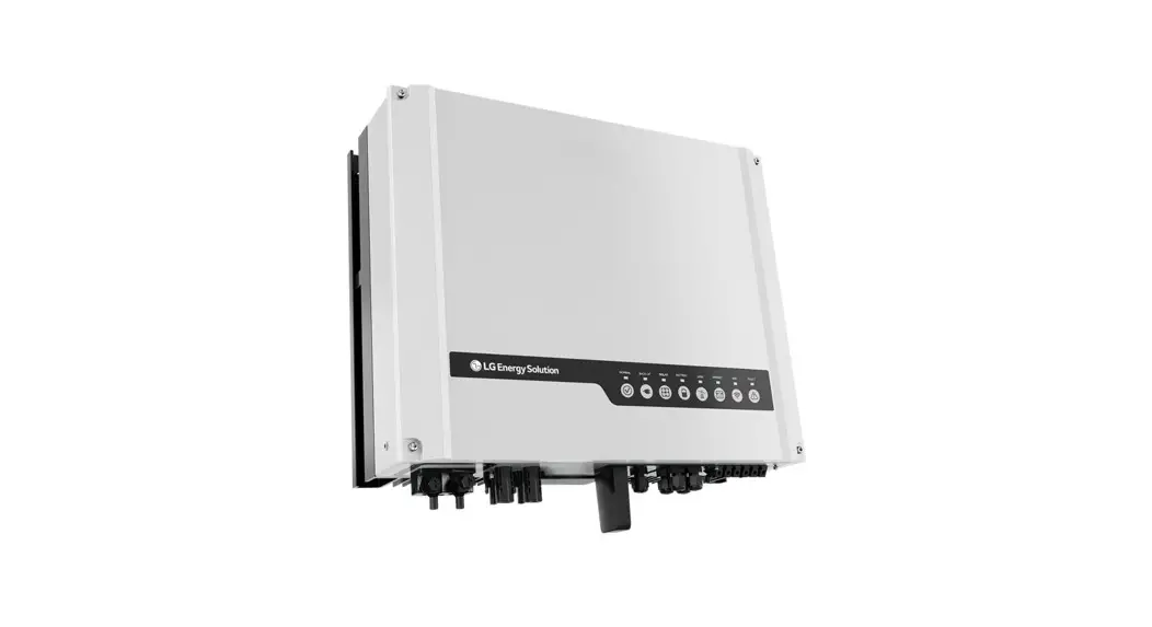
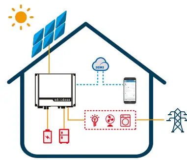
LGES-5048 is a hybrid or bidirectional solar inverter, applicable to solar systems connected to the utility grid and LG Energy Solution RESU 48V batteries. The Inverter should not be installed in multiple phase combinations.
The energy produced by the PV system is used to power household loads, charge the battery, and export excess energy to the utility grid. When household loads exceed PV production, the battery is discharged to support the loads and minimize utility grid import.
With the optional addition of remote control, such as Virtual Power Plant (VPP) participation, the inverter and battery combination can further optimise energy usage according to price signals.
Note:
The introduction describes a general working situation of the LGES system. The operation mode can be adjusted on LGES PV Master App up to the system layout. The general operation modes are as below:
1.1 Operation Modes Introduction
LGES system normally has the following operation modes based on your con figuration and layout.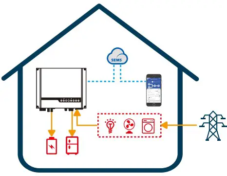
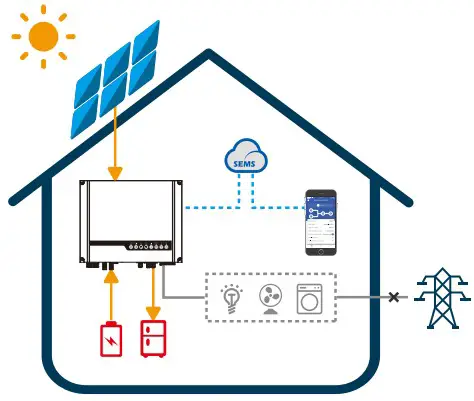
Mode Ⅰ
The energy produced by the PV system is used to optimised self-consumption. The excess energy is used to recharge the batteries, the rest is exported to grid.Mode Ⅱ
When there is no PV, and the battery is sufficient, it can supply the load together with grid power.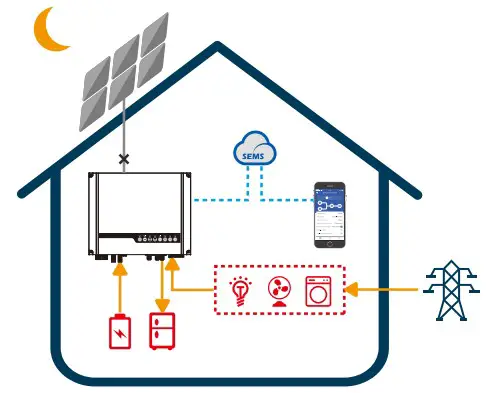
Mode Ⅲ
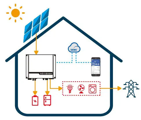
When grid fails, the system automatically switches to Back-Up mode. The Back-Up load can be supported by PV and battery.Mode Ⅳ
Battery could be charged by grid, and charge time/power could be set on LGES PV Master or remotely controlled.
1.2 Safety & Warning
LGES-5048 from LG Energy Solution Ltd strictly complies with related safety rules for product design and testing. Please read and follow all the instructions and cautions on the inverter or user manual during installation, operation or maintenance. Improper operation might cause personal or property damage.
Symbols Explanation
Caution!
Failure to observe a warning indicated in this manual may result in injury.![]()
Danger of high voltage and electric shock! 
Danger of hot surface! ![]()
Components of the product can be recycled. ![]()
This side up! The package must always be transported, handled and stored in such a way as the arrows always point upwards. ![]()
No more than six (6) identical packages being stacked on each other. 
Products should not be disposed as household waste. ![]()
Fragile – The package/product should be handled carefully and never be tipped over or slung. ![]()
Refer to the operating instructions. ![]()
Keep dry! The package/product must be protected from excessive humidity and must be stored under cover. ![]()
This symbol indicates that you should wait at least 5mins after disconnecting the inverter from the utility grid and from the PV panel before touching any inner live parts. 
CE mark
Safety Warning
Installation and operation of the inverter must be performed by qualified electricians, in compliance with all local standards, wiring rules and requirements of local grid authorities, e.g. AS 4777 and AS/NZS 3000 in Australia.
Before any wiring connection or electrical operation on the inverter, all battery and AC power must be disconnected from inverter for at least 5 minutes to make sure inverter is totally isolated to avoid electric shock.
The temperature of inverter surface might exceed 60℃ during operation, so please make sure it has cooled down before touching it, and make sure the inverter is out of reach of children.
Do not open the inverter’s cover or change any components without manufacturer’s authorisation, otherwise the warranty commitment for the inverter will be invalid.
Usage and operation of the inverter must follow the instructions in this user manual, otherwise the protection design might be impaired and warranty commitment for the inverter will be invalid.
Appropriate methods must be adopted to protect inverter from static damage. Any damage caused by static is not warranted by manufacturer.
PV negative (PV-) and battery negative (BAT-) on inverter side is not grounded as default design. Connecting PV- to EARTH is strictly forbidden.
PV modules used on the inverter must have an IEC61730 class A rating, and the total open-circuit voltage of PV string/array must lower than the maximum rated DC input voltage of the inverter. Any damage caused by PV over-voltage is beyond warranty.
The inverter, with built-in RCMU, will exclude possibility of DC residual current to 6mA, thus in the system an external RCD (type A) can be used(≥30mA).
In Australia, the inverter internal switching does NOT maintain Neutral integrity, which must be addressed by external connection arrangements like in the system connection diagram for Australia on page 16.
In Australia, output of back-up side in switchbox should be labeled on “Main Switch UPS Supply”.
The output of normal load side in switch box should be labeled “Main Switch Inverter Supply”.
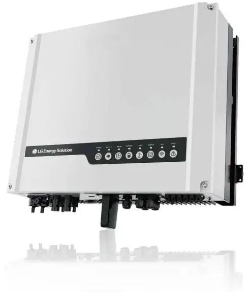
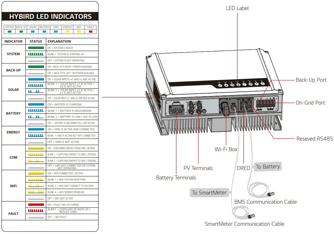
1.3 Product Overview
INSTALLATION INSTRUCTIONS
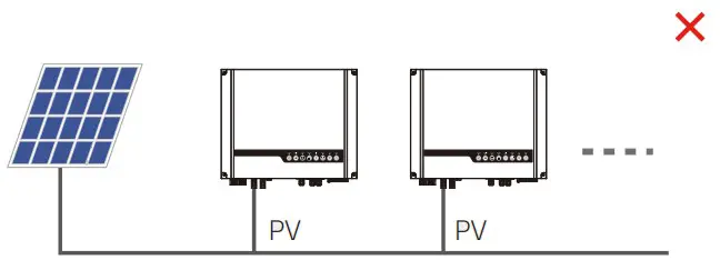
2.1 Unacceptable Installations
Please avoid the following installations which will damage the system or the Inverter.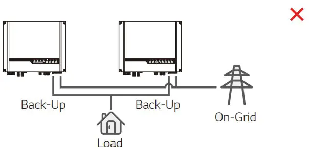
For general version, back-up cannot connect in parallel For further advance application, please contact after-sales. One meter cannot be connected to multiped inverters. And different CTs cannot be connected to the same line cable. 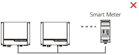
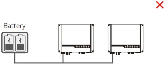
One meter cannot be connected to multiple inverters, and different CTs cannot connect to a same line cable. One battery bank cannot be connected to multiple inverters. 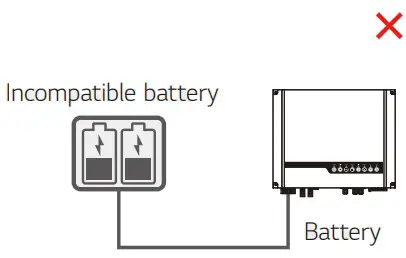
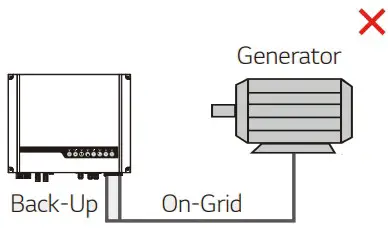
On-Grid or back-up side cannot be connected to any AC generator. Inverter battery input cannot be connected to incompatible batteries. 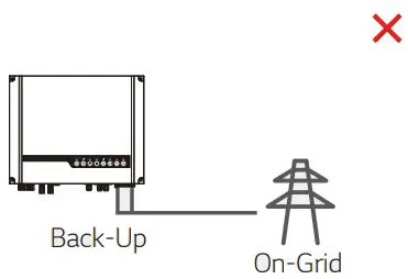
Back-up side cannot be connected to grid.
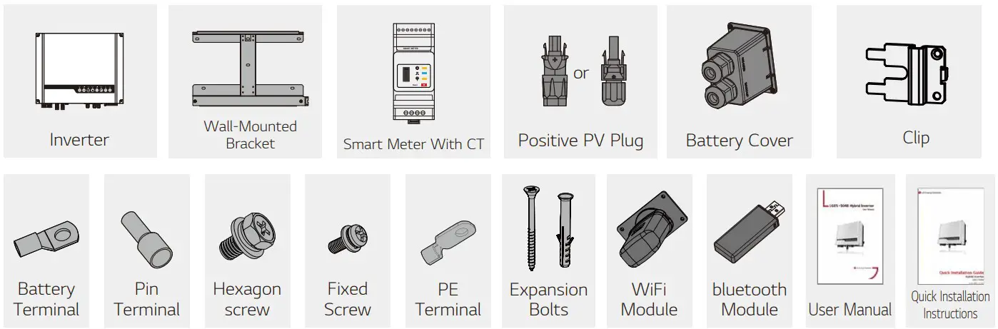
2.2 Packing List
Upon receiving the hybrid inverter, please check if any of the components as shown below are missing or broken.
2.3 Mounting
2.3.1 Select Mounting Location
For inverter’s protection and convenient maintenance, mounting location for inverter should be selected carefully based on the following rules:
Any part of this system shouldn’t block the switch and breaker from disconnecting the inverter from DC and AC power.
Rule 1. Inverter should be installed on a solid surface, where it is suitable for inverter’s dimensions and weight.
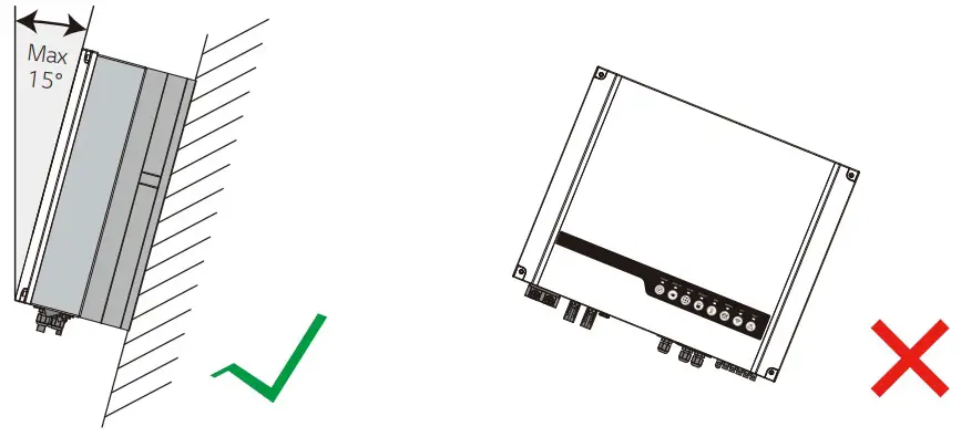
Rule 2. Inverter should be installed vertically or lie on a slope by a max of 15°.
Rule 3. Ambient temperature should be lower than 45°C. (High ambient temperature will cause power de-rating of inverter.)
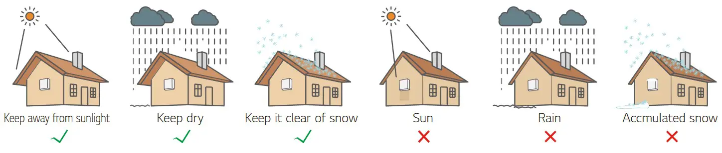
Rule 4. The inverter installation should be protected under shelter from direct sunlight or bad weather like snow, rain, lightning etc.
Rule 5. Inverter should be installed at eye level for convenient maintenance.
Rule 6. Product label on inverter should be clearly visible after installation.
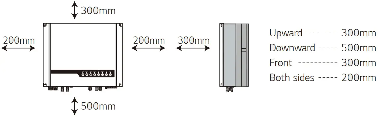
Rule 7. Leave enough space around the inverter according to the below figure.
Inverter cannot be installed near flammable, explosive or strong electro-magnetic equipment.
2.3.2 Mounting![]() Remember that this inverter is heavy! Please be careful when lifting out from the package.
Remember that this inverter is heavy! Please be careful when lifting out from the package.
The inverter is suitable for mounting on concrete or other non-combustible surface only.
Step 1
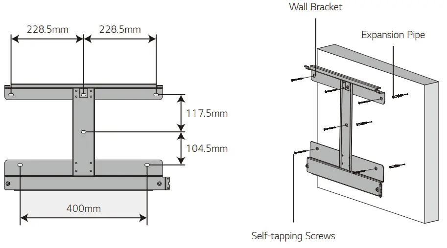
Please use the mounting bracket as a template to drill 4 holes in the right positions (10mm in diameter, and 80mm in depth).
Use expansion bolts in accessory box and fix the mounting bracket onto the wall tightly.
Note: Bearing capacity of the wall must be higher than 30kg.
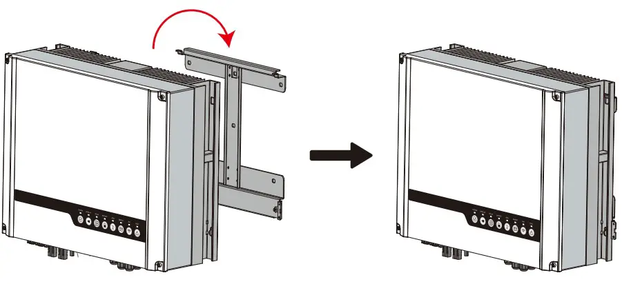
Step 2
Carry the inverter by holding the heatsink on two sides and place the inverter on the mounting bracket.Step 3
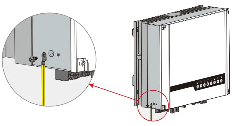
Ground cable shall be connected to ground plate on grid side.Step 4
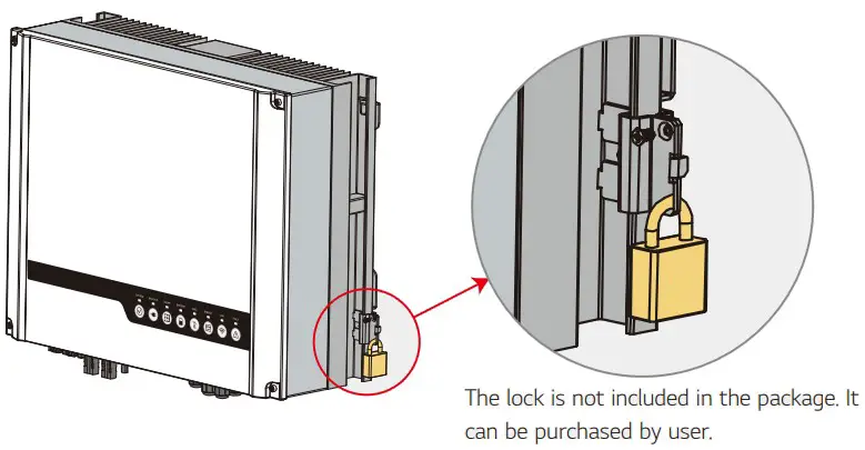
Inverter can be locked for anti-theft purposes if required.2.4 Electrical Wiring Connection
2.4.1 PV Wiring Connection
Before connecting PV panels/strings to inverter, please make sure requirements are followed as below:
- The total short-circuit current of PV string must not exceed inverter’s max DC current.
- The minimum isolation resistance to ground of the PV string must exceed 19.33kΩ in case of any shock hazard.
- PV string must not connect to earth/grounding conductor.
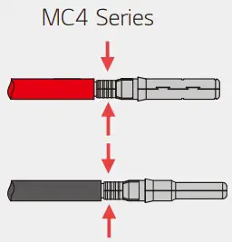
- Use the right PV plugs in the accessory box. (BAT plugs are similar to PV plugs, please confirm before use it.)
Note: There will be MC4 plugs in accessory box. The details of connections are as below.
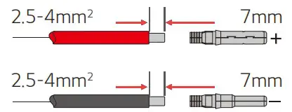
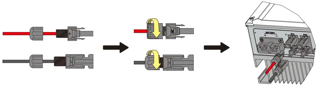
Step 1
Prepare PV cables and PV plugs.
Note:
- Please use PV plugs and connectors from accessory box.
- PV cable should be standard 2.5-4mm².
Step 2
Connect PV cables to PV connectors.Note:
- PV cables must be tightly crimped into the connectors.
- There will be a click sound if connectors are inserted correctly into PV plugs.
Step 3
Screw the cap on and plug it onto inverter side.
Note: There will be a click sound if connectors are inserted correctly into PV plugs.
![]() Reversing the polarity of PV strings could cause damage to the inverter.
Reversing the polarity of PV strings could cause damage to the inverter.
2.4.2 Battery Wiring Connection
Please be careful about any electric shock or chemical hazard.
Make sure there is an external DC breaker (125A) connected to the battery circuit.![]() Make sure that the breaker is off and battery is LG Energy Solution RESU 6.5/10/12/13 48V nominal battery only before connecting battery to inverter. Make sure inverter is totally isolated from PV and AC power.
Make sure that the breaker is off and battery is LG Energy Solution RESU 6.5/10/12/13 48V nominal battery only before connecting battery to inverter. Make sure inverter is totally isolated from PV and AC power.
Battery cables requirement as Figure 2.4.2-1.
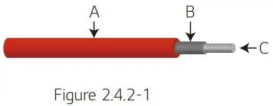
| Grade | Description | Value |
| A | Outside Diameter Insulation | 10-14 mm |
| B | Isolation Section | NA |
| C | Conductor Core Section | 35mm |
Battery wiring connection process
Step 1
Prepare battery cables and accessories and put battery power cable through battery cover.
Note:
- Please use accessories from accessory box.
- Battery power cable should be 35mm².
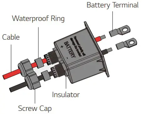
Step 2
Make battery terminals
- Strip cable coat, revealing 10mm length of metal core.
- Use special crimper to compress battery terminal tightly.
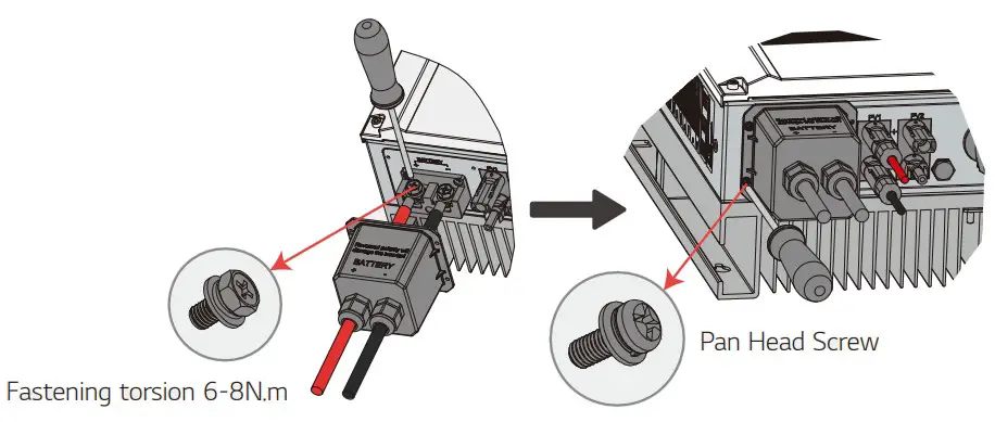
Step 3
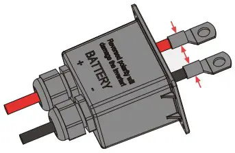
Connect battery terminal onto inverter .
Note:
Please make sure polarity (+/-) of battery are not reversed.
- For the compatible LG RESU batteries, please refer to battery connection in LGES-5048 QUICK INSTALLATION INSTRUCTIONS.
Battery Protection
Battery will provide charge/discharge current limitation under the following conditions:
- Battery SOC is lower than I-DOD (Depth of discharge).
- Battery voltage is lower than discharge voltage.
- Battery over temperature protection.
- Battery communication is abnormal for lithium battery.
- MS charge/discharge limitation. When charge/discharge current limitation protection happens:
- Battery charge/discharge operation could be abnormal.
- Under grid outage condition, Back-up supply will shutdown.
- It is not allowed to use the inverter in a pure off-grid scenario.
Note: - The inverter and battery cannot be used in off-grid designs
- Under on-grid mode, battery is protected from over discharge by DOD and discharge voltage.
- The DOD setting of a battery prevents the inverter from discharging battery reserve power. As soon as the DOD is reached the load of building will only be supported by either PV power or the grid. If there are continuous days when little or no battery charging occurs, the battery may continue to self-consume energy to support communications with the inverter.
2.4.3 On-Grid & Back-Up Connection
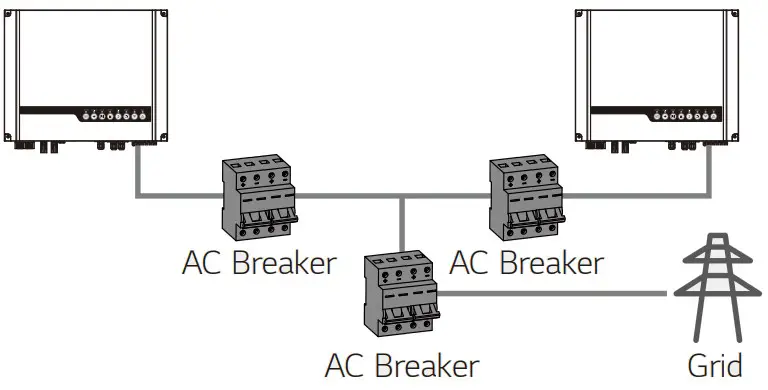
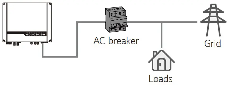
An external AC breaker is needed for on-grid connection to isolate from grid when necessary. The requirements of on-grid AC breaker are shown below.Inverter model AC breaker specification LGES-5048 40A / 230V (e.g. DZ47-60 C40)
Note: The absence of AC breaker on back-up side will lead to inverter damage if an electrical short circuit happens on back-up side.
- Use separated AC breaker for individual inverter.

- On the AC side, the individual breaker should be connected between inverter and Grid but before loads.
AC cable is required to connect to both on-grid and back-up side.![]() Make sure the inverter is totally isolated from any DC or AC power before connecting AC cable.
Make sure the inverter is totally isolated from any DC or AC power before connecting AC cable.
Note:
- Neutral cable shall be blue, line cable shall be black or brown (preferred) and protective earth cable shall be yellow-green.
- For AC cables, PE cable shall be longer than N&L cables, so in case that the AC cable slips or is taken out, the protecting earth conductor will be the last to take the strain.
Step 1
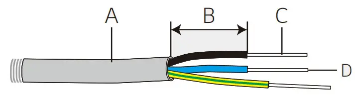
Prepare the terminals and AC cables according to the right table.Grade Description Value A Outside diameter 13-18 mm B Separated wire length 20-25 mm C Conductor wire length 7-9 mm D Conductor core section 4-6 mm
Step 2
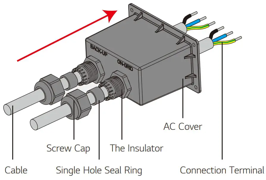
Put AC cable through terminal cover as shown in the figure.
Note: Please use the terminals in accessory box.Step 3
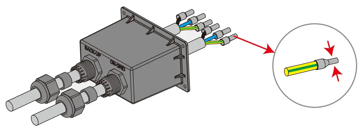
Press the 6 connectors on cable conductor core tightly.
Note: Make sure cable jacket is not locked within the connector.
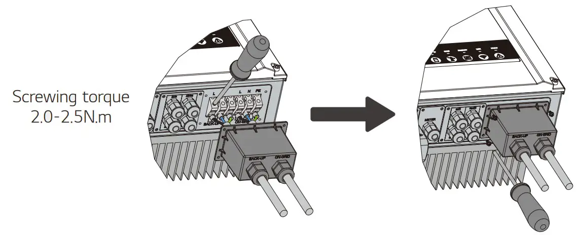
Step 4
- Connect the assembled AC cables into AC terminals with fastening torque about 2.0-2.5N.m. Note: Connect back-up terminals before connecting on-grid terminals. Make sure it is not connected to a wrong side.
- Lock the cover and screw the cap.
Special Adjustable Settings
The inverter has a field where the user can set functions, such as trip points, trip time, time of reconnection, active and invalid of QU curve and PU curve etc. by special firmware. Please contact after-sales for the special firmware and adjustable methods.
Declaration For Back-Up Function
The back-up output of LGES hybrid inverters have limited overload ability.
For details please refer to the technical parameters (Page 29).
The inverter has self-protection de-rating at high ambient temperature.
The following statement lays out general policies governing LGES-5048.
- Standard PV installation typically consists of the connection of the inverter with both panels and battery. In the case where the system is not connected to the batteries, the back-up function should not be used. Connection of back-up function without battery will not be covered by warranty and installer will be liable for any consequences arising from users not following this instruction.
- Under normal circumstances, the back-up switching time is less than 10 ms (the minimal condition to be considered as the UPS level). However, some external factors may cause the system to failing on back-up mode. As such, we recommend the users to be aware of conditions and follow the instructions as below:
• Do not connect loads when they are dependent on a stable energy supply for a reliable opera- tion.
• DO NOT connect loads which may in total exceed the maximum back-up capacity. Even when grid is present, this will cause overload .
• Try to avoid those loads which may create very high start-up current surges such as air-conditioner, high-power pump etc.
• Due to the condition of the battery itself, battery current might be limited by some factors including but not limited o the temperature, weather etc.
Accepted Loads:
LGES-5048 inverter is able to supply a continuous 4600VA output or maintain a 6900VA output less than 10 seconds on back-up side to support loads. The inverter also has self-protection for de-rating at high ambient temperature.
- Inductive Load: Maximum 1.5kVA for single inductive load, maximum 2.5kVA for total inductive load power.
- Capacitive Load: Total capacitive load (like computer, switch power etc.)power ≤3.0kVA. (Any load with high inrush current at start-up is not accepted)
Note:
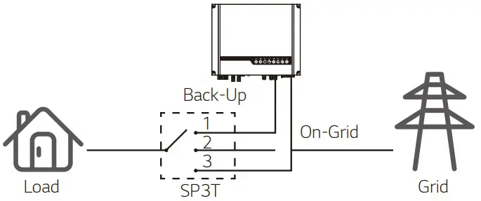
For convenient maintenance, it is recommended to install a SP3T switch on back-up and on-grid side. Then it is adjustable to support load by back-up or by grid or default settings.
- Back-up load is supplied from back-up side.
- Back-up load is isolated.
- Back-up load is supplied from grid side.
Declaration For Back-Up Overload Protection
Inverter will restart itself if overload protection triggers. The preparation time for restarting will be longer and longer (one hour at most) if overload protection repeats. Take following steps to restart inverter immediately.
Decrease back-up load power within maximum limitation.
On LGES PV Master → Advanced Setting → Click “Reset Back-Up Overload History”.
2.4.4 Smart Meter & CT Connection![]() Make sure AC cable is totally isolated from AC power before connecting Smart Meter & C T.
Make sure AC cable is totally isolated from AC power before connecting Smart Meter & C T.
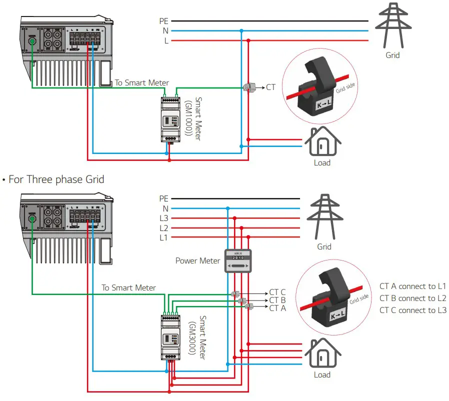
The Smart Meter with CT in product box is compulsory for LGES system installation, used to detect grid voltage and current direction and magnitude, further to instruct the operation condition of LGES inverter via RS485 communication.
Note:
- The Smart Meter with CT is well configured, please do not change any setting on Smart Meter.
- One Smart Meter can only be used for one LGES series inverter.
- If LGES is used in a three-phase grid with a three-phase smart meter, the three CTs must be used for one Smart Meter, and must be connected on the same phase with Smart Meter power cable.
Smart Meter & CT Connection Diagram
- For Single phase Grid
Note:
- CT cable is 3m as default, please do not extend.
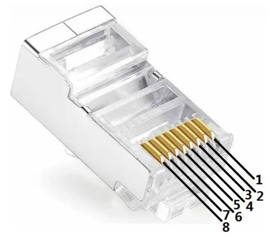
- Smart Meter communication cable (RJ45) is attached on the inverter (“To Smart Meter” cable), could be extended to max 100m, and must use standard RJ45 cable and plug, as below:
- Single-phase Smart Meter GM1000 is supplied with inverter. For 3-phase grid, use optional GM3000 (available from distributor)
Detailed Pin Function Of Each Port On ES
BMS: CAN communication is configured by default. If 485 communication is used, please contact after-sales to replace with the corresponding communication line.
| Position | Color | BMS Function | Smart Meter Function | EMS |
| 1 | Orange&white | 485_A2 | NC | 485_A |
| 2 | Orange | NC | NC | 485_B |
| 3 | Green&white | 485_B2 | 485_B1 | 485_A |
| 4 | Blue | CAN_H | NC | NC |
| 5 | Blue&white | CAN_L | NC | NC |
| 6 | Green | NC | 485_A1 | 485_B |
| 7 | Brown & white | NC | 485_B1 | NC |
| 8 | Brown | NC | 485_A1 | NC |
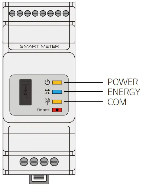
Smart Meter LED Indications
| STATUS | OFF | ON | Blinking |
| POWER | Not working | Working | / |
| ENERGY | / | Importing | Exporting |
| COM | Blink one time when it transfer data to inverter |
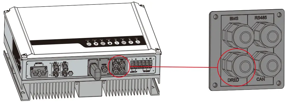
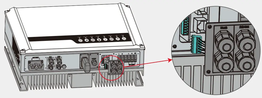
2.5 DRED & Remote Shutdown Device Connection
DRED (Demand response enabling device) is used for Australia safety requirements. Inverter integrates control logic and provides an interface for DRED. The DRED is not provided by inverter manufacturer.
Detailed connection of DRED & Remote Shutdown are shown below:
Step 1
Screw this plate off from the inverter.
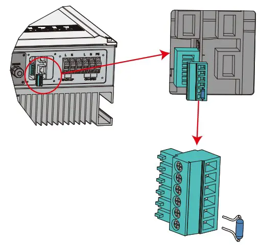
Note: DRED should be connected through “DRED Port” as the figure shows.Step 2
- Plug out the 6-pin terminal and dismantle the resistor on it.
- Plug the resistor out, leave the 6-pin terminal for next step.
Note: The 6-pin terminal in the inverter has the same function as DRED. Please leave it in the inverter if no external device is connected.
Step 3-1 For DRED
- Put DRED cable through the plate.
- Connect DRED cable on the 6-pin terminal.The function of each connection position is shown as below.
| NO. | 1 | 2 | 3 | 4 | 5 | 6 |
| Function | DRM1/5 | DRM2/6 | DRM3/7 | DRM4/8 | REFGEN | COM / DRMO |
Step 3-2 For Remote Shutdown
- Put the cable through the plate.
- Wiring from the No. 5 and 6 holes respectively.
| NO. | 5 | 6 |
| Function | REFGEN | COM / DRMO |
Step 4
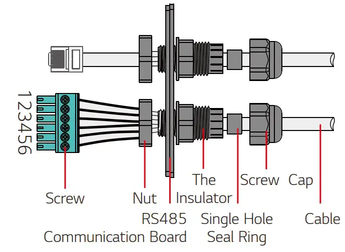
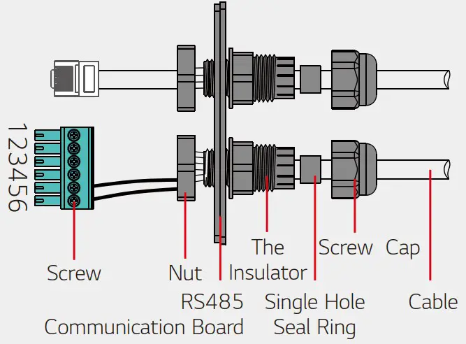
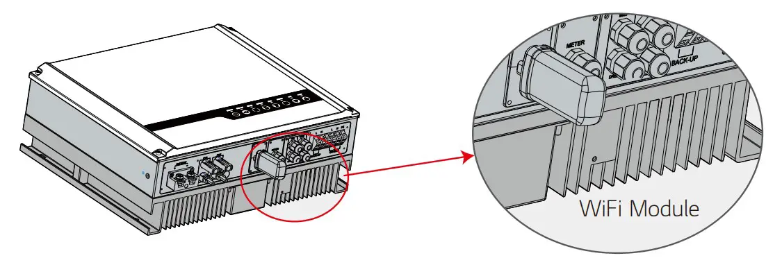
Connect DRED terminal to the right position onto the inverter.2.6 WiFi Module Connection
The Wi-Fi communication function is only applied to WiFi Module, please refer to the digram below to install the Wi-Fi module.
The detailed configuration instruction can be referred to “3.1 Wi-Fi Configuration” in this manual or “LGES-5048 Quick Installation Instruction” in the accessory box. 2.7 Earth Fault Alarm Connection
LGES-5048 inverter complies with IEC 62109-2 13.9. Fault indicator LED on inverter cover will light up and the system will email the fault information to customer.
Inverter should be installed at eye level for convenient maintenance.
2.8 RESU Home Monitor
RESU Home Monitor is an online monitoring system. After completing the installation of communication connection, you can access www.lgresuhomemonitor.com
Please contact after-sales for more operation of RESU Home Monitor.

Wiring System for LGES-5048 Hybrid Inverter
Note: This diagram indicates wiring structure of inverter, not the electric wiring standard.
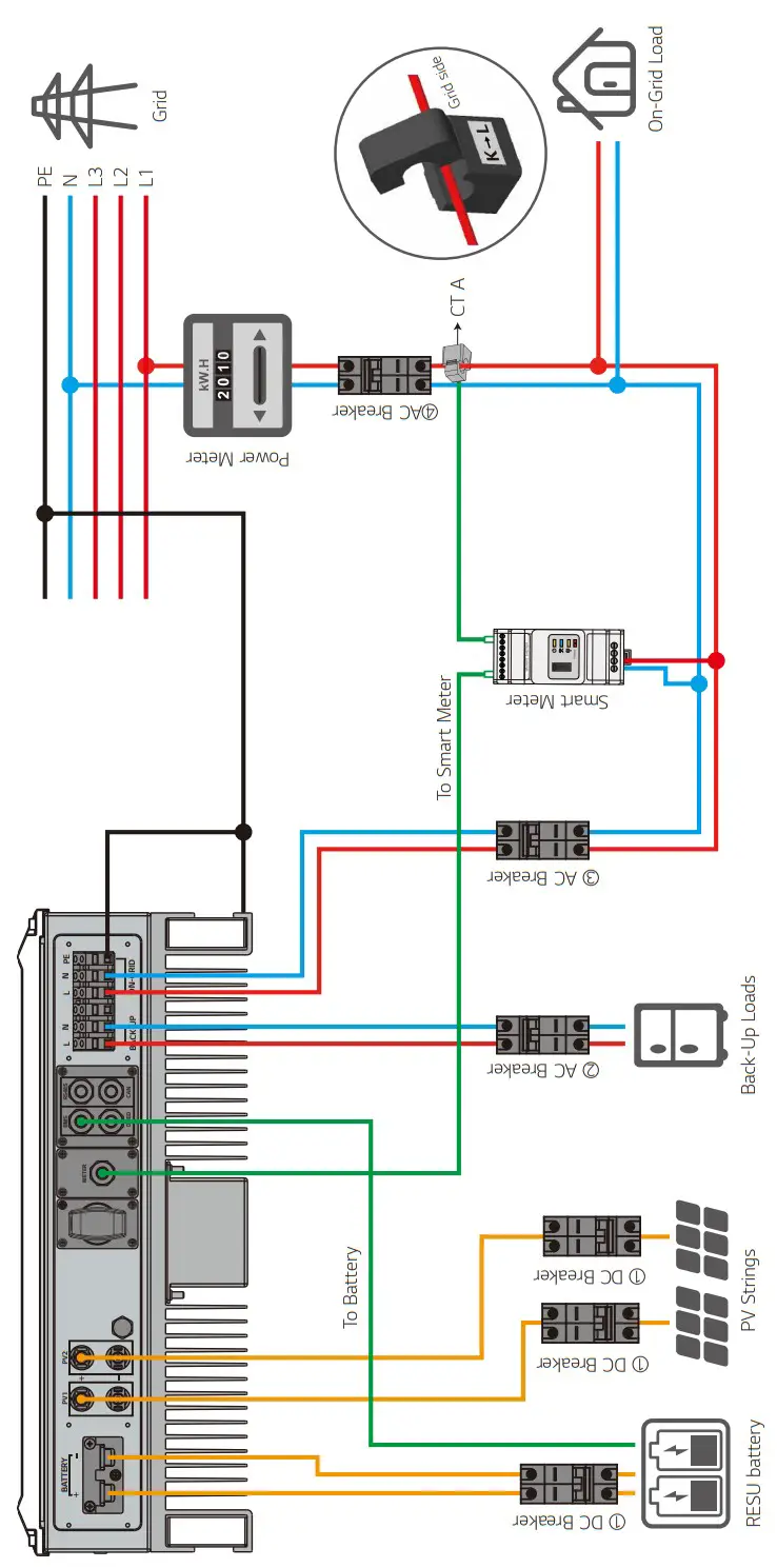
Please select Breaker according to the specification below
| Inverter | ① | ② | ③ | ④ |
| LGES-5048 | 125A/60V DC breaker | 32A/230V AC breaker | 20A/230V AC breaker | Depends on household loads |
- Only for RESU 48V battery which has BMS communication.
- Direction of the CT cannot be connected in reverse, please follow “House→ Grid” direction to do the connection.
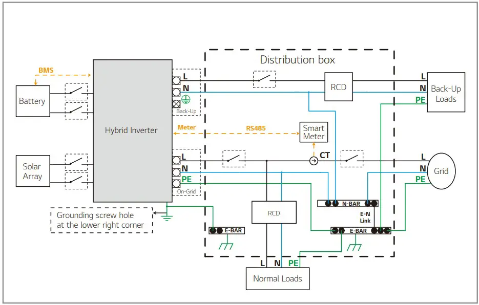
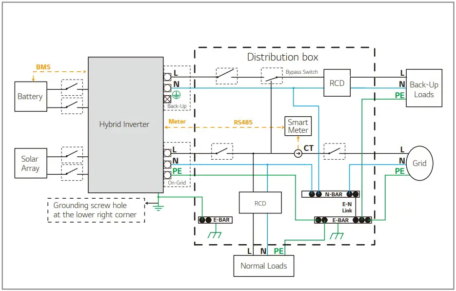
System Connection Diagram
Note: According to Australian requirements, the neutral cable of on-grid side and back-up side must be connected together, otherwise back-up function will not work.Wiring with SP3T Bypass Switch
Note:
The purpose of SP3T bypass switch is to allow for continued operation of back-up loads in case of inverter fault. SP3T bypass switch is not provided with inverter, it can be purchased from electrical wholesalers.
SYSTEM OPERATION
3.1 Wi-Fi Configuration
This part shows con figuration on web page. You can also complete the con figuration with LGES PV Master. Wi-Fi con figuration is absolutely necessary for online monitoring and maintenance. Preparation:
- Inverter must be powered up with battery or grid power.
- Router with available internet access to the website www.lgresuhomemonitor.com is required.
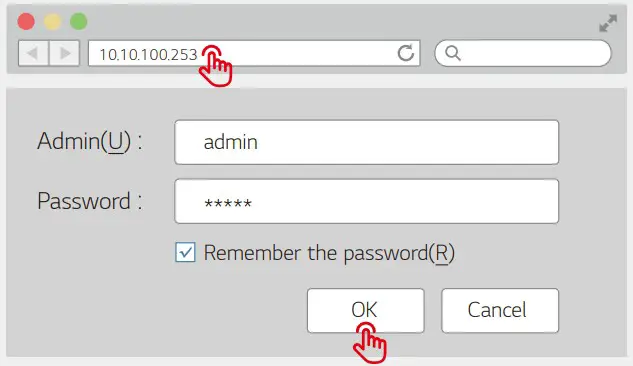
Step 1
- Connect Solar-WiFi* to your PC or smart phone (* its named the last 8 character of the inverter’s serial No.) ; Password:12345678.
- Open browser and login 10.10.100.253 Admin (User): admin; Password: admin.
- Then click “OK”.
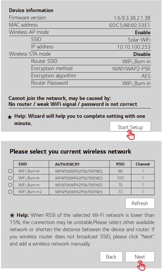
Step 2
- Click “Start Setup” to choose your router.
- Then click “Next”.
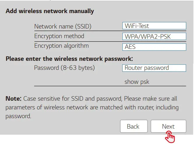
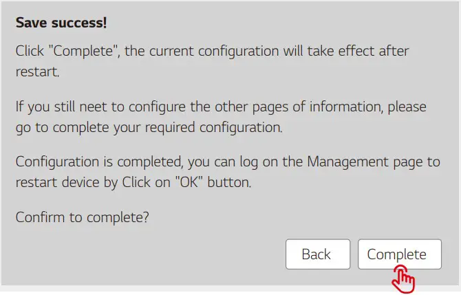
Step 3
- Fill in the password of ther router, then click “Next”.
- Click “Complete”.
Note:
If the Wi-Fi module fails to connect after correct passwords are entered, check that there are not special characters used that are not supported by module.(Supported standard characters: 0~9, a~z, A~Z, supported special characters: `~!@#$%^&*()_+-=[]\{}|;’:<>? ,./”, characters not mentioned above are not supported by default.)
Note:
- Please make sure the password, Encryption method / algorithm is the same as the router’s.
- Under normal operation, the Wi-Fi LED on inverter will change from double blink to quadruple blink then to solid status, which means Wi-Fi has connected to the server successfully.
- Wi-Fi configuration could also be done on LGES PV Master, details please check on LGES PVMaster.
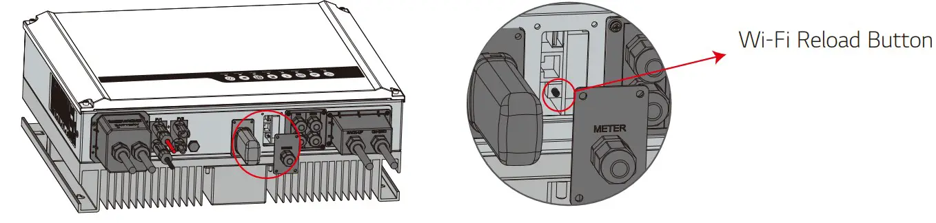
Wi-Fi Reset & Reload
Wi-Fi reset means restarting Wi-Fi module. Wi-Fi settings will be reprocessed and saved automatically. Wi-Fi Reload means setting Wi-Fi module back to default factory setting.Wi-Fi Reset
Short press reset button.
Wi-Fi LED will blink for a few seconds.
Wi-Fi Reload
Long press reset button (longer than 3s).
Wi-Fi LED will double blink until Wi-Fi configuration again.
Note:
Wi-Fi reset & reload function is only used when:
- Wi-Fi loses connection to internet or cannot connect to LGES PV Master successfully.
- Cannot find “Solar-WiFi signal” or have other Wi-Fi configuration problems.
- Please do not use this button if Wi-Fi monitoring works well.
- If you need to replace the module, please use the unlock tool. 4:21 PM 95048EHU12345678 VIRGIN
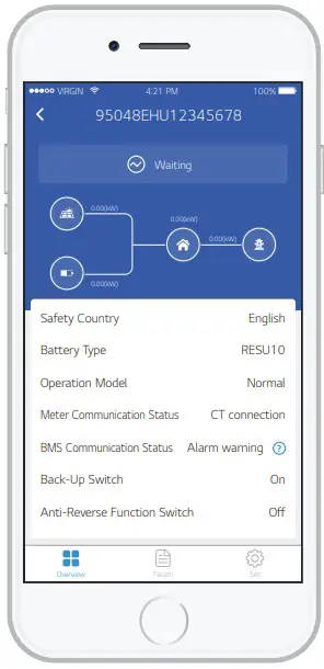
3.2 LGES PV Master
LGES PV Master is an external monitoring /configuration application for hybrid inverters, used on smart phones or tablet for both Android and iOS system. Features include:
- Edit system configuration according to customer needs
- Check firmware version
- Set safety region by country and region A, B or C according to local utility requirement
- Adjust export limit
- Monitor and check the performance of the hybrid system
Please download “LGES PV Master User Manual” at https://www.lgessbattery.com#mmm_au/home-battery/product-info.lg?sn=362
NOTE:
For Australian safety region, set to A, B or C, according to local utility requirement.
After the setting is completed, some parameters will take effect according to region, such as PU curve, QU curve, trip protection etc. To change settings, please refer to the LGES PV User Manual.

3.3 Start-up/shutdown Procedure
Shutdown Procedure:
- Turn off either the “MAIN SWITCH (INVERTER SUPPLY)” located in the switchboard or the “INVERTER AC ISOLATOR” adjacent to or below the inverter.
- Turn off all “PV ARRAY D.C. ISOLATOR(S)” located adjacent to or below the inverter.
- If a battery is connected to the inverter, turn off “BATTERY DC ISOLATOR”.
Start-up Procedure:
- Turn on all “PV ARRAY D.C. ISOLATOR(S)” located adjacent to or below the inverter.
- If a battery is connected to the inverter, turn on “BATTERY DC ISOLATOR”.
- Turn on either the “MAIN SWITCH (INVERTER SUPPLY)” located in the switchboard or the “INVERTER AC ISOLATOR” adjacent to or below the inverter.
OTHERS
4.1 Error Messages
The error messages below will be displayed on LGES PV Master or reported by e-mail if an error occurs.
| ERROR MESSAGE | EXPLANATION | REASON | SOLUTIONS |
| Utility Loss | Public grid power is not available (Power lost or on-gnu connection fails) | Inverter does not detect the connection of gnu | I Check (use rnLibmeter)of AC see lw.: volts}` Make sure Tel power is (nab* 2 Make Wit AC cattle. are acceded tightly and well 3 If all it Nara. dealt try to turn off AC breaker and turn en again in 5 more. |
| VAC Failure | Grid voltage rs not within permissible range | Inverter detects that AC voltage is beyond the normal range required by the safety country |
1 Make sure safety country of the newer is at right |
| FAC Failure | Grid frequency is not when permissible range | Inverter detects that the gad frequency is beyond the normal range required by the safety country | I Make sure the safety country of the natter is set ngt 2 If safety country is right then please check on the mercer dept. ay of AC frequency (Few) it %than a named range 3 If FAC faker only appears a few once and is rescind :con it *cub be calleted by occasional yid Frequency Leonel: day |
| Over Temperature | Temperature inside of the inverter too high | The inverter’s working environment leads to a high temperature condition | I. Try to decrease surrounding tertiPttatl.tt 2 Make awe the retaliation complies wth the nstructen on tweeter Leer manual 3 Try to close the inner for 15 mm, Net start up egan |
| Isolation Failure | ISO failure could be caused by muluplereasons like PV panels are not grounded well DC cablers broken. PV panels are aged or surrounding humidity is comparatively higher. etc | Isolation failure could be caused by multiple reasons like that the PV panels are not grounded wet DC cable is broken PV panels are aged or surrounding humidity is comparatively heavy. etc | I Use multi-meter to check of the resistance between earth a ornerier frame it der< to zero If its not, pler.e azure that the connection is wee 2 IF the hurrackty it too high, relation fallers may occur 3 Chedt the resistance between PVI •/PY2•/BAT•/PS/- to earth If the re-.manse is bower than 333k the* the system wing correction 4 Try to restart the nvenerCheck of the fault slit oco-re If not 4 means a is caused by an occasional situation or contact after-sale: |
| Ground Failure | Ground leakage current is too high | Ground failure could be caused by multiple reasons like that the neutral cable on the AC side ts not connected well or the surrounding humidity is comparatively heavy. etc. | Check (use multyrneter) if there rs voltage (normally should be close to OY) between earth a whetter frame If there is a %cher it means the neutral a ground cables are not connected well on the ACstle If it happens only on the early morning/dawn /rainy days with higher as humidity arid is recovered soon, it chat be nonnal |
| Relay Check Failure | Stiff checking of relay failure | Neutral 8. ground cables are not connected well on AC side or lust an occasional failure | Check (use manometer) of there it high voltage Venally should be loner than I OV) between N a et table on the AC tide If the ‘6teqc it tare than I W it means the Need a road table are not eenneetea well on AC due or restart envier |
| DC Injection High | / | The inverter detects a higher DC component in AC output | Try to rent the nverteedeck aft sty stag occurs note is yea an =amend outmatch Others contact attendees mediately |
| EEPROM R/W Failure | / | Caused by a strong external magnetic feel etc. | Try to restart the swenercheck if it and aturtlf note is pet an occasions tauten Other< contact efter-nn cemedtatdy |
| SRI Failure | Internal communication fads | Caused by a strong external magnetic field etc. | Try to restart the swenercheck l it zed occultly note is rust an ecotone.’ otubain Tolerance contact after-file: rreredsately |
| DC Bus High | BUS voltage is knee-high | / | Try to restart the nvertgtheck distil occur-AI nay: e. Just an cecasoord nutate Other me. to t after-sire rmedatdy |
| Back-Up Overload | Back-up side is overloaded | Total back-up load power is higher than the back-up nominal cutout power | Decrease back-up loads to make sure the total load power is lower than back-up nominal output power (please refer to page 11). |
4.2 Troubleshooting
For PC: https://www.lgessbattery.com/au/home-battery/product-info.lg?sn=362
For Mobile: https://www.lgessbattery.com#mmm_au/home-battery/product-info.lg?sn=362

https://www.lgessbattery.com#mmm_au/home-battery/product-info.lg?sn=362
Questions & Answers (Q & A)
Q: Why can’t I find the Solar-WiFi* signal on mobile devices?
– A: Normally Solar-WiFi* signal can be found right after inverter has powered up. But Solar-Wi- Fi signal will disappear when LGES connects to internet. If changes to the setting are required, connect to the router for change. If you can’t find the WiFi signal or connect to the router, then please try to reload Wi-Fi (please refer to User manual page 18).
– A: The Wi module can only connect to one device at a time. If the signal is already connected to another device at the time for some reason, you cannot connect to the signal.
– A: It’s possible that there are special characters not supported by module in the hotspot passwords. Please modify the password to consist of only Arabic numerals or uppercase /lowercase letters.
Q: Why does the battery not discharge when grid is not available, while it discharges normally when grid is available?
– A: On the App, off -grid output and back-up function should be turned on to make battery discharge under off -grid mode.
– A: For back-up supply, the “Back-Up Supply” on LGES PV Master must be turned on. Under off -grid mode or when grid power is disconnected, “Off -Grid Output Switch” function must be turned on as well.
– Note: When turning “Off-Grid Output Switch” on, don’t restart inverter or battery, otherwise the function will be switched off automatically.
– A: Battery will stop charging when battery voltage reaches charge voltage set on LGES PV Master.
– A: The switch of RESU battery normally trips because of following reasons:
1. Battery DIP switches not set correctly
2. BMS communication fails. (10 minute delay to trip)
3. Battery Voltage is too low (<35V), battery trips to protect itself.
4. An electrical short-cut happened on battery connection side. Or for other reasons please contact after-sales.
– A: LG Energy Solution RESU6.5, RESU10, RESU12, RESU13 (end of line)
Q: Why can’t I save settings on LGES PV Master?
– A: It could be caused by losing connection to Solar-WiFi *.
1. Make sure you have already connected Solar-WiFi* (make sure no other devices connected) or router (if connected Solar-WiFi* to router). App’s homepage shows connection well.
2. Make sure you restart inverter 10mins after you change some settings because inverter will save settings every 10 mins under normal mode. We recommend to change setting parameters when inverter is in wait mode.
– A: The data refresh frequency is different, so there will be a data inconformity between different pages on the App as well as between these on portal and App.
– A: NA means App does not receive data from inverter or server because of communication problem, such as battery communication, and communication between inverter and the App.
Q: How to activate output power limit function?
– A: The function can be realised as follows:
1. Make sure Smart Meter connection and communication is functioning.
2. Turn on export power limit function and set the max output power to grid on App.
– Note: Even if output power limit is set to 0W, there might still be a deviation of a max of 100W exporting to grid.
– A: Export limit can be 0W theoretically, but there can be a measurement deviation of around 50-100W.
– A: Generally, no, because the communication protocol is integrated into inverter and Smart Meter, other brand meters cannot communicate. Also any manual setting change could cause Meter communication failure. An exception is when using an LG Energy Solution approved meter for VPP operations.
– A: The max current for CT is 120A.
Q: Is there a quick way to make the system work?
– A: For the shortest way, please refer to “LGES-5048 Quick Installation Instructions” and “LGES PV Master Instruction”.
– A: Please refer to user manual on page 12.
– A: Normally we still provide technical support to problems caused from disobeying the instructions on the user manual, however we cannot guarantee any replacements or returns. So if there is any special conditions where you cannot 100% follow the instructions, please contact after-sales for suggestions.
4.3 Disclaimer
The LGES-5048 inverter is transported, used and operated under environmental and electrical conditions. Manufacturer has the right not to provide after-sales services or assistance under following conditions:
- Inverter is damaged during transfer.
- Inverter is out of warranty year and extended warranty is not bought.
- Inverter is installed, refitted or operated in improper ways without authority from manufacturer.
- Inverter is installed or used under improper environment or technical condition mentioned in this user manual, without authority from manufacturer.
- Installation or configuration of the inverter does not follow requirements mentioned in this user manual.
- The inverter is installed or operated against the requirements or warnings that are mentioned in this user manual.
- Inverter is broken or damaged by any force majeure like lightning, earthquake, fire hazard, storm and volcanic eruption etc.
- Inverter is disassembled, changed or updated on software or hardware without authority from manufacturer.
- Inverter is installed, used or operated against any related items in international or local policies or regulations.
- Any non-compatible batteries, loads or other devices connected to inverter.
Note: Manufacturer will keep the right to explain all the contents in this user manual. To ensure IP65, inverter must be sealed well, please install the inverters within one day after unpacking, otherwise please seal all unused terminals / holes, unused terminals / holes are not allowed to be kept open, confirm that there is no risk of water or dust entering the terminals / holes.
Maintenance
The inverter requires periodical maintenance, details are shown below:
- Make sure inverter is totally isolated from all DC and AC power for at least 5 mins before maintenance.
- Heat sink: Please use clean towel to clean up heat sink once a year.
- Torque: Please use torque wrench to tighten AC and DC wiring connection once a year.
- DC breaker: Check DC breaker regularly, active the DC breaker 10 times in a row once a year.
- Operating DC breaker will clean contacts and extend lifespan of DC breaker.
4.4 Technical Parameters
Technical Data
Battery Input Data
| Battery Type *1 | Li-Ion |
| Nominal Battery Voltage (V) | 48 |
| Max. Charging Voltage (V) | ≤60 (Configurable) |
| Max. Charging Current (A) *1 | 100 |
| Max. Discharging Current (A) *1 | 100 |
| Max. Charging/Discharging power (W) | 4600 |
| Nominal Battery Capacity (Ah) | 126~252 |
| Charging Mode for Li-Ion Battery | Self-adaption to BMS |
PV String Input DataMax DC Input Power with battery (W) 7500 Max DC Input Power without battery (W) 6500 Max. DC Input Voltage (V) 580 MPPT Range (V) 125~550 Start-up Voltage (V) 125 Min. Feed-in Voltage(V) *2 150 MPPT Range for Full Load (V) 215~500 Nominal DC Input Voltage (V) 360 Max. Input Current (A) 11-Nov Max. Short Current (A) 13.8/13.8 No. of MPP Trackers 2 No. of Strings per MPP Tracker 1
AC Output Data (On-grid)Nominal Apparent Power Output to Utility Grid (VA)7 5000 Max. Apparent Power Output to Utility Grid (VA) *3 5000 Nominal Apparent Power from Utility Grid (VA) 9200 Max. Apparent Power from Utility Grid (VA) 9200 Nominal Output Voltage (V) 230 Nominal Output Frequency (Hz) 50/60 Max. AC Current Output to Utility Grid (A) 24.5 Max. AC Current From Utility Grid (A) 40 Output Power Factor ~1 (Adjustable from 0.8 leading to 0.8 lagging) Output THDi (@Nominal Output) <3%
AC Output Data (Back-up)Back-up Nominal apparent power (VA) 4600 Max. Output Apparent Power (VA) 4600 Peak Output Apparent Power (VA) *4 6900, 10sec Max. Output Current (A) 20 Nominal Output Voltage (V) 230 (±2%) Nominal Output Frequency (Hz) 50/60 (±0.2%) Output THDv (@Linear Load) <3%
- The actual charge and discharge current also depends on the battery.
- When there is no battery connected, inverter starts feeding in only if string voltage is higher than 200V.
- 4600 for VDE 0126-1-1 &VDE-AR-N4105 &NRS 097-2-1, 5100 for CEI 0-21.
| Technical Data | LGES-5048 |
| Efficiency | |
| Max. Efficiency | 97.60% |
| Max. Battery to Load Efficiency | 94.00% |
| Europe Efficiency | 97.00% |
| MPPT Efficiency | 99.90% |
| Protection | |
| Anti-islanding Protection | Integrated |
| PV String Input Reverse Polarity Protection | Integrated |
| Insulation Resistor Detection | Integrated |
| Residual Current Monitoring Unit | Integrated |
| Output Over Current Protection | Integrated |
| Output Short Protection | Integrated |
| Output Over Voltage Protection | Integrated |
| General Data | |
| Operating Temperature Range (℃ ) | -25~60 |
| Relative Humidity | 0~95% |
| Operating Altitude (m) | 3000 |
| Cooling | Natural Convection |
| Noise (dB) | <25 |
| User Interface | LED & APP |
| Communication with BMS *5 | RS485; CAN |
| Communication with Meter | RS485 |
| Communication with Portal | Wi-Fi |
| Weight (kg) | 30 |
| Size (Width*Height*Depth mm ) | 516*440*184 |
| Mounting | Wall Bracket |
| Protection Degree | IP65 |
| Standby Self Consumption (W) | <13 |
| Topology | Battery Isolation |
| Certifications & Standards *6 | |
| Grid Regulation | VDE-AR-N 4105; |
| VDE 0126-1-1 | |
| EN 50549-1;G99,G100; | |
| CEI 0-21;AS/NZS4777.2 | |
| NRS 097-2-1; | |
| Safety Regulation | IEC62109-1&2, IEC62040-1 |
| EMC | EN61000-6-3, EN61000-6-4 |
| EN 61000-4-16, EN 61000-4- | |
| EN 61000-4-29 |
*4: Can be reached only if PV and battery power is enough.
*5: CAN communication is configured by default.
*6: Not all certifications & standards listed, check the official website for details.
*7: 4600 for VDE 0126-1-1 &VDE-AR-N4105 &NRS 097-2-1, 4600 for CEI 0-21.
4.5 Other Test
For Australian requirements, in the THDi test, Zref should be added between inverter and mains.
RA, XA for Line conductor
RN, XN for Neutral conductor
Zref:
RN=0, 16; XN=j0,10 at 50Hz

LG Energy Solution Australia Pty Ltd
Unit 12, 35 Dunlop Rd, Mulgrave, VIC 3170
Support Tel. : 1300 178 064 [AEST Business hours]Support email : [email protected]
©2021 LG Energy Solution ESS Battery Division
PARC1, 108, Yeoui-daero, Yeongdeungpo-gu, Seoul, Republic of Korea, 07335
www.lqhomebattery.com/au
https://www.lciensolcom
340-00568-02


